2008 NISSAN LATIO relay
[x] Cancel search: relayPage 1422 of 2771
EC-348
< SERVICE INFORMATION >
DTC P0448 EVAP CANISTER VENT CONTROL VALVE
Diagnosis Procedure
INFOID:0000000001702856
1.CHECK RUBBER TUBE
1. Turn ignition switch OFF.
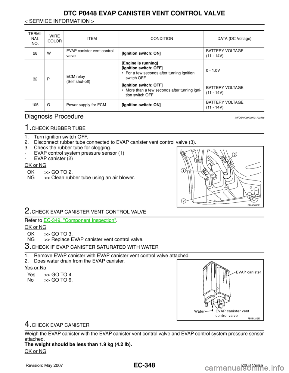
2. Disconnect rubber tube connected to EVAP canister vent control valve (3).
3. Check the rubber tube for clogging.
- EVAP control system pressure sensor (1)
- EVAP canister (2)
OK or NG
OK >> GO TO 2.
NG >> Clean rubber tube using an air blower.
2.CHECK EVAP CANISTER VENT CONTROL VALVE
Refer to EC-349, "
Component Inspection".
OK or NG
OK >> GO TO 3.
NG >> Replace EVAP canister vent control valve.
3.CHECK IF EVAP CANISTER SATURATED WITH WATER
1. Remove EVAP canister with EVAP canister vent control valve attached.
2. Does water drain from the EVAP canister.
Ye s o r N o
Ye s > > G O T O 4 .
No >> GO TO 6.
4.CHECK EVAP CANISTER
Weigh the EVAP canister with the EVAP canister vent control valve and EVAP control system pressure sensor
attached.
The weight should be less than 1.9 kg (4.2 lb).
OK or NG
TERMI-
NAL
NO.WIRE
COLORITEM CONDITION DATA (DC Voltage)
28 WEVAP canister vent control
valve[Ignition switch: ON]BATTERY VOLTAGE
(11 - 14V)
32 PECM relay
(Self shut-off)[Engine is running]
[Ignition switch: OFF]
• For a few seconds after turning ignition
switch OFF0 - 1.0V
[Ignition switch: OFF]
• More than a few seconds after turning igni-
tion switch OFFBATTERY VOLTAGE
(11 - 14V)
105 G Power supply for ECM[Ignition switch: ON]BATTERY VOLTAGE
(11 - 14V)
BBIA0693E
PBIB1213E
Page 1462 of 2771
EC-388
< SERVICE INFORMATION >
DTC P0461 FUEL LEVEL SENSOR
5. Turn ignition switch OFF and wait at least 10 seconds then turn
ON.
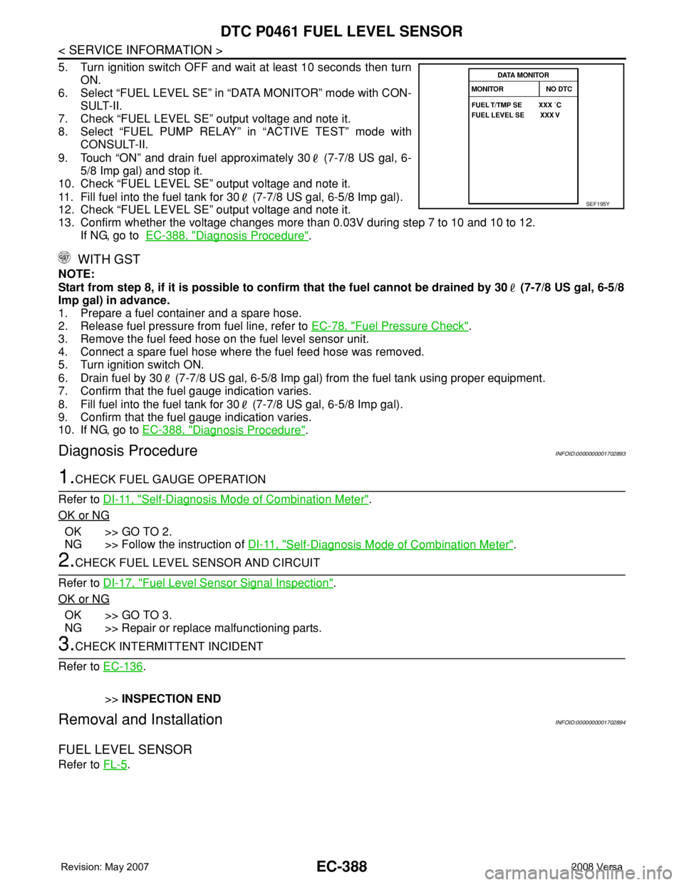
6. Select “FUEL LEVEL SE” in “DATA MONITOR” mode with CON-
SULT-II.
7. Check “FUEL LEVEL SE” output voltage and note it.
8. Select “FUEL PUMP RELAY” in “ACTIVE TEST” mode with
CONSULT-II.
9. Touch “ON” and drain fuel approximately 30 (7-7/8 US gal, 6-
5/8 Imp gal) and stop it.
10. Check “FUEL LEVEL SE” output voltage and note it.
11. Fill fuel into the fuel tank for 30 (7-7/8 US gal, 6-5/8 Imp gal).
12. Check “FUEL LEVEL SE” output voltage and note it.
13. Confirm whether the voltage changes more than 0.03V during step 7 to 10 and 10 to 12.
If NG, go to EC-388, "
Diagnosis Procedure".
WITH GST
NOTE:
Start from step 8, if it is possible to confirm that the fuel cannot be drained by 30 (7-7/8 US gal, 6-5/8
Imp gal) in advance.
1. Prepare a fuel container and a spare hose.
2. Release fuel pressure from fuel line, refer to EC-78, "
Fuel Pressure Check".
3. Remove the fuel feed hose on the fuel level sensor unit.
4. Connect a spare fuel hose where the fuel feed hose was removed.
5. Turn ignition switch ON.
6. Drain fuel by 30 (7-7/8 US gal, 6-5/8 Imp gal) from the fuel tank using proper equipment.
7. Confirm that the fuel gauge indication varies.
8. Fill fuel into the fuel tank for 30 (7-7/8 US gal, 6-5/8 Imp gal).
9. Confirm that the fuel gauge indication varies.
10. If NG, go to EC-388, "
Diagnosis Procedure".
Diagnosis ProcedureINFOID:0000000001702893
1.CHECK FUEL GAUGE OPERATION
Refer to DI-11, "
Self-Diagnosis Mode of Combination Meter".
OK or NG
OK >> GO TO 2.
NG >> Follow the instruction of DI-11, "
Self-Diagnosis Mode of Combination Meter".
2.CHECK FUEL LEVEL SENSOR AND CIRCUIT
Refer to DI-17, "
Fuel Level Sensor Signal Inspection".
OK or NG
OK >> GO TO 3.
NG >> Repair or replace malfunctioning parts.
3.CHECK INTERMITTENT INCIDENT
Refer to EC-136
.
>>INSPECTION END
Removal and InstallationINFOID:0000000001702894
FUEL LEVEL SENSOR
Refer to FL-5.
SEF195Y
Page 1486 of 2771
EC-412
< SERVICE INFORMATION >
DTC P1217 ENGINE OVER TEMPERATURE
DTC P1217 ENGINE OVER TEMPERATURE
System DescriptionINFOID:0000000001702929
SYSTEM DESCRIPTION
NOTE:
•If DTC P1217 is displayed with DTC U1000 or U1001, first perform the trouble diagnosis for DTC
U1000, U1001. Refer to EC-143
.
•If DTC P1217 is displayed with DTC U1010, first perform the trouble diagnosis for DTC U1010. Refer
to EC-145
.
Cooling Fan Control
*1: The ECM determines the start signal status by the signals of engine speed and battery voltage.
*2: This signal is sent to ECM through CAN communication line.
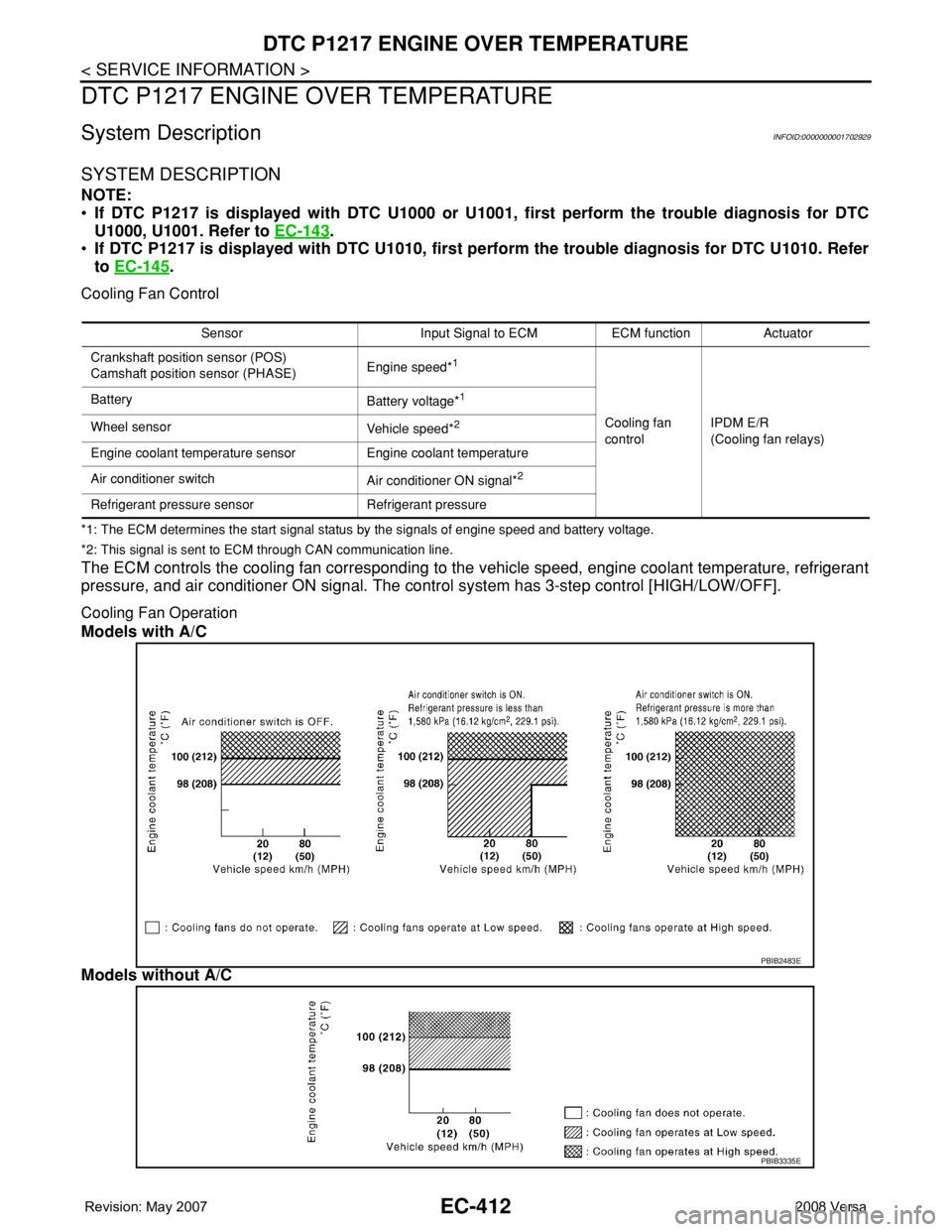
The ECM controls the cooling fan corresponding to the vehicle speed, engine coolant temperature, refrigerant
pressure, and air conditioner ON signal. The control system has 3-step control [HIGH/LOW/OFF].
Cooling Fan Operation
Models with A/C
Models without A/C
Sensor Input Signal to ECM ECM function Actuator
Crankshaft position sensor (POS)
Camshaft position sensor (PHASE)Engine speed*
1
Cooling fan
controlIPDM E/R
(Cooling fan relays) Battery
Battery voltage*
1
Wheel sensor
Vehicle speed*2
Engine coolant temperature sensor Engine coolant temperature
Air conditioner switch
Air conditioner ON signal*
2
Refrigerant pressure sensor Refrigerant pressure
PBIB2483E
PBIB3335E
Page 1487 of 2771
DTC P1217 ENGINE OVER TEMPERATURE
EC-413
< SERVICE INFORMATION >
C
D
E
F
G
H
I
J
K
L
MA
EC
N
P O Cooling Fan Relay Operation
The ECM controls cooling fan relays in the IPDM E/R through CAN communication line.
CONSULT-II Reference Value in Data Monitor ModeINFOID:0000000001702930
Specification data are reference values.
On Board Diagnosis LogicINFOID:0000000001702931
If the cooling fan or another component in the cooling system malfunctions, engine coolant temperature will
rise. When the engine coolant temperature reaches an abnormally high temperature condition, a malfunction
is indicated.
This self-diagnosis has the one trip detection logic.
CAUTION:
When a malfunction is indicated, be sure to replace the coolant. Refer to CO-8, "
Changing Engine
Coolant". Also, replace the engine oil. Refer to LU-7, "Changing Engine Oil".
1. Fill radiator with coolant up to specified level with a filling speed of 2 liters per minute. Be sure to
use coolant with the proper mixture ratio. Refer to MA-11, "
Anti-freeze Coolant Mixture Ratio".
2. After refilling coolant, run engine to ensure that no water-flow noise is emitted.
Overall Function CheckINFOID:0000000001702932
Use this procedure to check the overall function of the cooling fan. During this check, a DTC might not be con-
firmed.
WARNING:
Cooling fan speedCooling fan relay
123
Stop (OFF) OFF OFF OFF
Low (LOW) ON OFF OFF
High (HI) OFF ON ON
MONITOR ITEM CONDITION SPECIFICATION
AIR COND SIG• Engine: After warming up, idle
the engineAir conditioner switch: OFF OFF
Air conditioner switch: ON
(Compressor operates.)ON
COOLING FAN• Engine: After warming up, idle
the engine
• Air conditioner switch: OFFEngine coolant temperature: 97°C
(207°F) or lessOFF
Engine coolant temperature: Between
98°C (208°F) and 99°C (210°F) or
moreLOW
Engine coolant temperature: 100°C
(212°F) or moreHIGH
DTC No. Trouble diagnosis name DTC detecting condition Possible cause
P1217
1217Engine over temperature
(Overheat)• Cooling fan does not operate properly (Over-
heat).
• Cooling fan system does not operate properly
(Overheat).
• Engine coolant was not added to the system
using the proper filling method.
• Engine coolant is not within the specified
range.• Harness or connectors
(Cooling fan circuit is open or shorted.)
• Cooling fan
• IPDM E/R (Cooling fan relays)
•Radiator hose
•Radiator
• Reservoir tank
•Radiator cap
• Water pump
•Thermostat
• Water control valve
For more information, refer to EC-424,
"Main 13 Causes of Overheating".
Page 1530 of 2771

EC-456
< SERVICE INFORMATION >
DTC P2100, P2103 THROTTLE CONTROL MOTOR RELAY
DTC P2100, P2103 THROTTLE CONTROL MOTOR RELAY
Component DescriptionINFOID:0000000001702985
Power supply for the throttle control motor is provided to the ECM via throttle control motor relay. The throttle
control motor relay is ON/OFF controlled by the ECM. When the ignition switch is turned ON, the ECM sends
an ON signal to throttle control motor relay and battery voltage is provided to the ECM. When the ignition
switch is turned OFF, the ECM sends an OFF signal to throttle control motor relay and battery voltage is not
provided to the ECM.
CONSULT-II Reference Value in Data Monitor ModeINFOID:0000000001702986
Specification data are reference values.
On Board Diagnosis LogicINFOID:0000000001702987
These self-diagnoses have one trip detection logic.
FAIL-SAFE MODE
When the malfunction is detected, ECM enters fail-safe mode and the MIL lights up.
DTC Confirmation ProcedureINFOID:0000000001702988
NOTE:
If DTC Confirmation Procedure has been previously conducted, always turn ignition switch OFF and wait at
least 10 seconds before conducting the next test.
PROCEDURE FOR DTC P2100
With CONSULT-II
1. Turn ignition switch ON and wait at least 2 seconds.
2. Select “DATA MONITOR” mode with CONSULT-II.
3. Start engine and let it idle for 5 seconds.
4. If DTC is detected, go to EC-459, "
Diagnosis Procedure".
MONITOR ITEM CONDITION SPECIFICATION
THRTL RELAY • Ignition switch: ON ON
DTC No. Trouble diagnosis name DTC detecting condition Possible cause
P2100
2100Throttle control motor
relay circuit openECM detects a voltage of power source for
throttle control motor is excessively low.• Harness or connectors
(Throttle control motor relay circuit is
open)
• Throttle control motor relay
P2103
2103Throttle control motor
relay circuit shortECM detects the throttle control motor relay is
stuck ON.• Harness or connectors
(Throttle control motor relay circuit is
shorted)
• Throttle control motor relay
Engine operating condition in fail-safe mode
ECM stops the electric throttle control actuator control, throttle valve is maintained at a fixed opening (approx. 5 degrees) by the return
spring.
SEF058Y
Page 1531 of 2771
DTC P2100, P2103 THROTTLE CONTROL MOTOR RELAY
EC-457
< SERVICE INFORMATION >
C
D
E
F
G
H
I
J
K
L
MA
EC
N
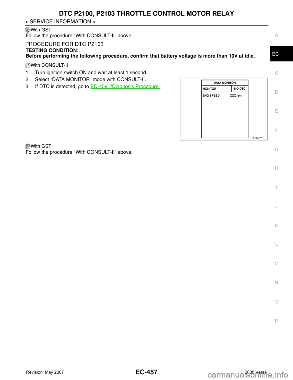
P O With GST
Follow the procedure “With CONSULT-II” above.
PROCEDURE FOR DTC P2103
TESTING CONDITION:
Before performing the following procedure, confirm that battery voltage is more than 10V at idle.
With CONSULT-II
1. Turn ignition switch ON and wait at least 1 second.
2. Select “DATA MONITOR” mode with CONSULT-II.
3. If DTC is detected, go to EC-459, "
Diagnosis Procedure".
With GST
Follow the procedure “With CONSULT-II” above.
SEF058Y
Page 1532 of 2771
EC-458
< SERVICE INFORMATION >
DTC P2100, P2103 THROTTLE CONTROL MOTOR RELAY
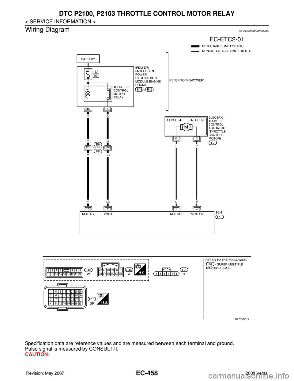
Wiring Diagram
INFOID:0000000001702989
Specification data are reference values and are measured between each terminal and ground.
Pulse signal is measured by CONSULT-II.
CAUTION:
BBWA2644E
Page 1533 of 2771
DTC P2100, P2103 THROTTLE CONTROL MOTOR RELAY
EC-459
< SERVICE INFORMATION >
C
D
E
F
G
H
I
J
K
L
MA
EC
N
P O
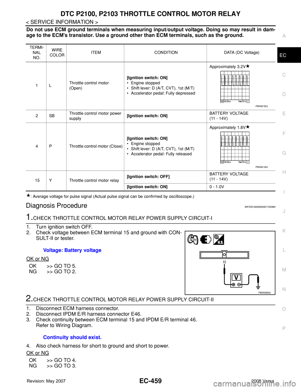
Do not use ECM ground terminals when measuring input/output voltage. Doing so may result in dam-
age to the ECM's transistor. Use a ground other than ECM terminals, such as the ground.
: Average voltage for pulse signal (Actual pulse signal can be confirmed by oscilloscope.)
Diagnosis ProcedureINFOID:0000000001702990
1.CHECK THROTTLE CONTROL MOTOR RELAY POWER SUPPLY CIRCUIT-I
1. Turn ignition switch OFF.
2. Check voltage between ECM terminal 15 and ground with CON-
SULT-II or tester.
OK or NG
OK >> GO TO 5.
NG >> GO TO 2.
2.CHECK THROTTLE CONTROL MOTOR RELAY POWER SUPPLY CIRCUIT-II
1. Disconnect ECM harness connector.
2. Disconnect IPDM E/R harness connector E46.
3. Check continuity between ECM terminal 15 and IPDM E/R terminal 46.
Refer to Wiring Diagram.
4. Also check harness for short to ground and short to power.
OK or NG
OK >> GO TO 4.
NG >> GO TO 3.
TERMI-
NAL
NO.WIRE
COLORITEM CONDITION DATA (DC Voltage)
1LThrottle control motor
(Open)[Ignition switch: ON]
• Engine stopped
• Shift lever: D (A/T, CVT), 1st (M/T)
• Accelerator pedal: Fully depressedApproximately 3.2V
2SBThrottle control motor power
supply[Ignition switch: ON]BATTERY VOLTAGE
(11 - 14V)
4 P Throttle control motor (Close)[Ignition switch: ON]
• Engine stopped
• Shift lever: D (A/T, CVT), 1st (M/T)
• Accelerator pedal: Fully releasedApproximately 1.8V
15 Y Throttle control motor relay[Ignition switch: OFF]BATTERY VOLTAGE
(11 - 14V)
[Ignition switch: ON]0 - 1.0V
PBIA8150J
PBIA8149J
Voltage: Battery voltage
PBIA9569J
Continuity should exist.