2008 NISSAN LATIO relay
[x] Cancel search: relayPage 1197 of 2771

TROUBLE DIAGNOSIS
EC-123
< SERVICE INFORMATION >
C
D
E
F
G
H
I
J
K
L
MA
EC
N
P O
INT/V SOL (B1)• Engine: After warming up
• Air conditioner switch: OFF
• Shift lever: P or N (A/T, CVT),
Neutral (M/T)
•No loadIdle 0% - 2%
When revving engine up to 2,000 rpm
quicklyApprox. 0% - 90%
AIR COND RLY• Engine: After warming up, idle the
engineAir conditioner switch: OFF OFF
Air conditioner switch: ON
(Compressor operates)ON
FUEL PUMP RLY• For 1 second after turning ignition switch ON
• Engine running or crankingON
• Except above conditions OFF
VENT CONT/V • Ignition switch: ON OFF
THRTL RELAY • Ignition switch: ON ON
COOLING FAN• Engine: After warming up, idle the
engine
• Air conditioner switch: OFFEngine coolant temperature: 97°C
(207°F) or lessOFF
Engine coolant temperature: Between
98°C (208°F) and 99°C (210°F)LOW
Engine coolant temperature: 100°C
(212°F) or moreHIGH
HO2S2 HTR (B1)• Below 3,600 rpm after the following conditions are met.
- Engine: After warming up
- Keeping the engine speed between 3,500 and 4,000 rpm for 1 minute and
at idle for 1 minute under no loadON
• Engine speed: Above 3,600 rpm OFF
I/P PULLY SPD • Vehicle speed: More than 20 km/h (12 MPH)Almost the same speed as the
tachometer indication
VEHICLE SPEED• Turn drive wheels and compare CONSULT-II value with the speedometer
indication.Almost the same speed as the
speedometer indication
TRVL AFTER MIL • Ignition switch: ONVehicle has traveled after MIL has
turned ON.0 - 65,535 km
(0 - 40,723 mile)
A/F S1 HTR (B1)• Engine: After warming up, idle the engine
(More than 140 seconds after starting engine.)4 - 100%
AC PRESS SEN• Engine: Idle
• Air conditioner switch: ON (Compressor operates)1.0 - 4.0V
VHCL SPEED SE• Turn drive wheels and compare speedometer indication with the CONSULT-
II value.Almost the same speed as the
speedometer indication
SET VHCL SPD • Engine: Running ASCD: OperatingThe preset vehicle speed is
displayed.
MAIN SW • Ignition switch: ONMAIN switch: Pressed ON
MAIN switch: Released OFF
CANCEL SW • Ignition switch: ONCANCEL switch: Pressed ON
CANCEL switch: Released OFF
RESUME/ACC SW • Ignition switch: ONRESUME/ACCELERATE switch:
PressedON
RESUME/ACCELERATE switch: Re-
leased
OFF
SET SW • Ignition switch: ONSET/COAST switch: Pressed ON
SET/COAST switch: Released OFF MONITOR ITEM CONDITION SPECIFICATION
Page 1212 of 2771
EC-138
< SERVICE INFORMATION >
POWER SUPPLY AND GROUND CIRCUIT
Diagnosis Procedure
INFOID:0000000001702606
1.INSPECTION START
Start engine.
Is engine running?
Ye s o r N o
Ye s > > G O T O 8 .
No >> GO TO 2.
2.CHECK ECM POWER SUPPLY CIRCUIT-I
1. Turn ignition switch OFF and then ON.
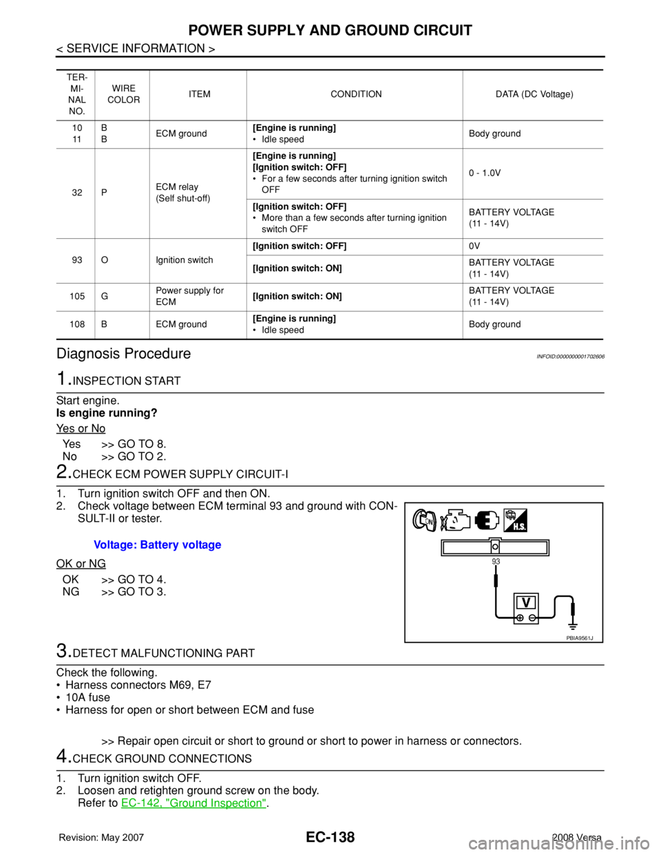
2. Check voltage between ECM terminal 93 and ground with CON-
SULT-II or tester.
OK or NG
OK >> GO TO 4.
NG >> GO TO 3.
3.DETECT MALFUNCTIONING PART
Check the following.
• Harness connectors M69, E7
• 10A fuse
• Harness for open or short between ECM and fuse
>> Repair open circuit or short to ground or short to power in harness or connectors.
4.CHECK GROUND CONNECTIONS
1. Turn ignition switch OFF.
2. Loosen and retighten ground screw on the body.
Refer to EC-142, "
Ground Inspection".
TER-
MI-
NAL
NO.WIRE
COLORITEM CONDITION DATA (DC Voltage)
10
11B
BECM ground[Engine is running]
• Idle speedBody ground
32 PECM relay
(Self shut-off)[Engine is running]
[Ignition switch: OFF]
• For a few seconds after turning ignition switch
OFF0 - 1.0V
[Ignition switch: OFF]
• More than a few seconds after turning ignition
switch OFFBATTERY VOLTAGE
(11 - 14V)
93 O Ignition switch[Ignition switch: OFF]0V
[Ignition switch: ON]BATTERY VOLTAGE
(11 - 14V)
105 GPower supply for
ECM[Ignition switch: ON]BATTERY VOLTAGE
(11 - 14V)
108 B ECM ground[Engine is running]
• Idle speedBody ground
Voltage: Battery voltage
PBIA9561J
Page 1238 of 2771
EC-164
< SERVICE INFORMATION >
DTC P0075 IVT CONTROL SOLENOID VALVE
Do not use ECM ground terminals when measuring input/output voltage. Doing so may result in dam-
age to the ECM's transistor. Use a ground other than ECM terminals, such as the ground.
: Average voltage for pulse signal (Actual pulse signal can be confirmed by oscilloscope.)
Diagnosis ProcedureINFOID:0000000001702645
1.CHECK INTAKE VALVE TIMING CONTROL SOLENOID VALVE POWER SUPPLY CIRCUIT
1. Turn ignition switch OFF.
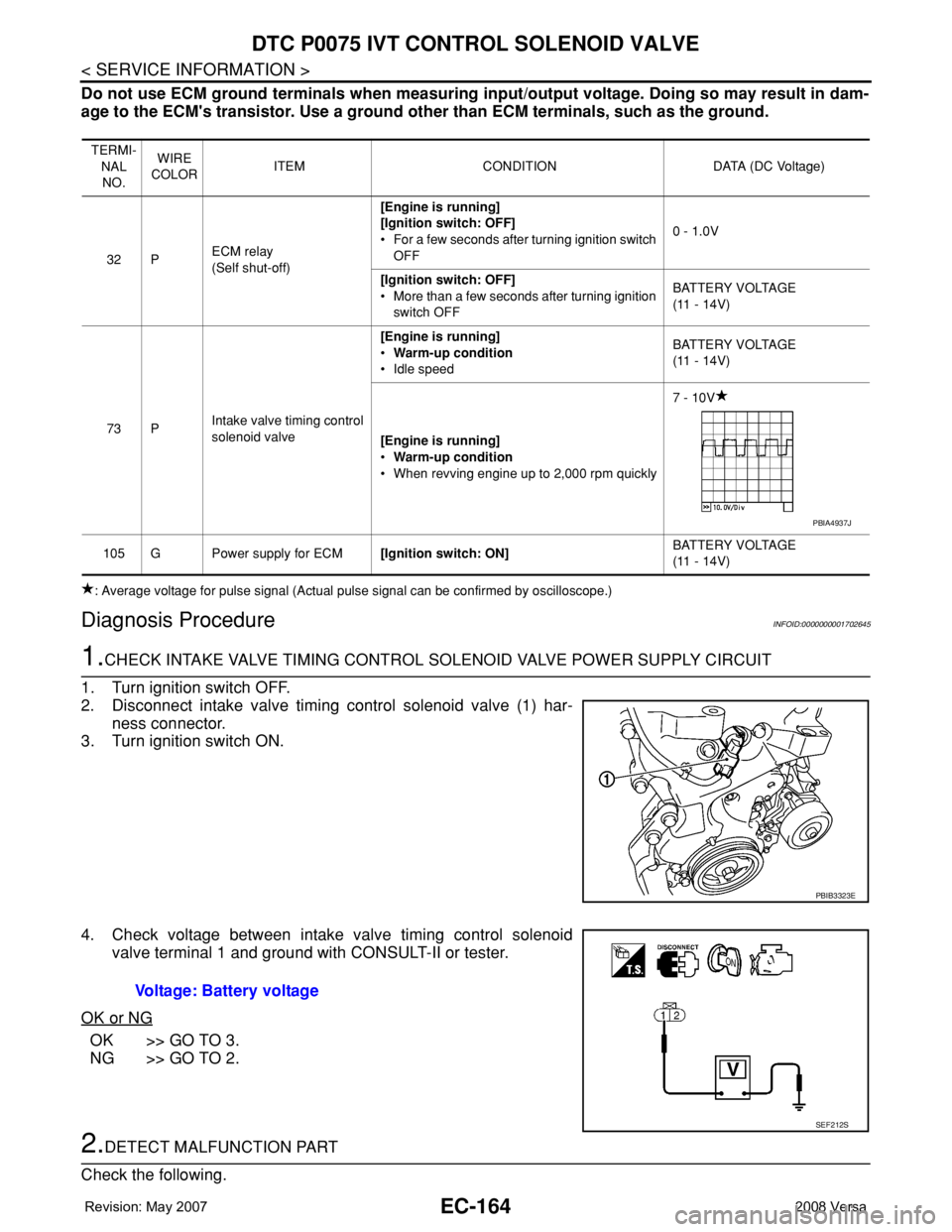
2. Disconnect intake valve timing control solenoid valve (1) har-
ness connector.
3. Turn ignition switch ON.
4. Check voltage between intake valve timing control solenoid
valve terminal 1 and ground with CONSULT-II or tester.
OK or NG
OK >> GO TO 3.
NG >> GO TO 2.
2.DETECT MALFUNCTION PART
Check the following.
TERMI-
NAL
NO.WIRE
COLORITEM CONDITION DATA (DC Voltage)
32 PECM relay
(Self shut-off)[Engine is running]
[Ignition switch: OFF]
• For a few seconds after turning ignition switch
OFF0 - 1.0V
[Ignition switch: OFF]
• More than a few seconds after turning ignition
switch OFFBATTERY VOLTAGE
(11 - 14V)
73 PIntake valve timing control
solenoid valve[Engine is running]
•Warm-up condition
• Idle speedBATTERY VOLTAGE
(11 - 14V)
[Engine is running]
•Warm-up condition
• When revving engine up to 2,000 rpm quickly7 - 10V
105 G Power supply for ECM[Ignition switch: ON]BATTERY VOLTAGE
(11 - 14V)
PBIA4937J
PBIB3323E
Voltage: Battery voltage
SEF212S
Page 1245 of 2771
DTC P0101 MAF SENSOR
EC-171
< SERVICE INFORMATION >
C
D
E
F
G
H
I
J
K
L
MA
EC
N
P O
Diagnosis ProcedureINFOID:0000000001702654
1.INSPECTION START
Which malfunction (A or B) is duplicated?
A or B
A >> GO TO 3.
B >> GO TO 2.
2.CHECK INTAKE AIR LEAK
Check the following for connections.
• Air duct
• Vacuum hoses
• Intake air passage between air duct and intake manifold
OK or NG
OK >> GO TO 3.
NG >> Reconnect the parts.
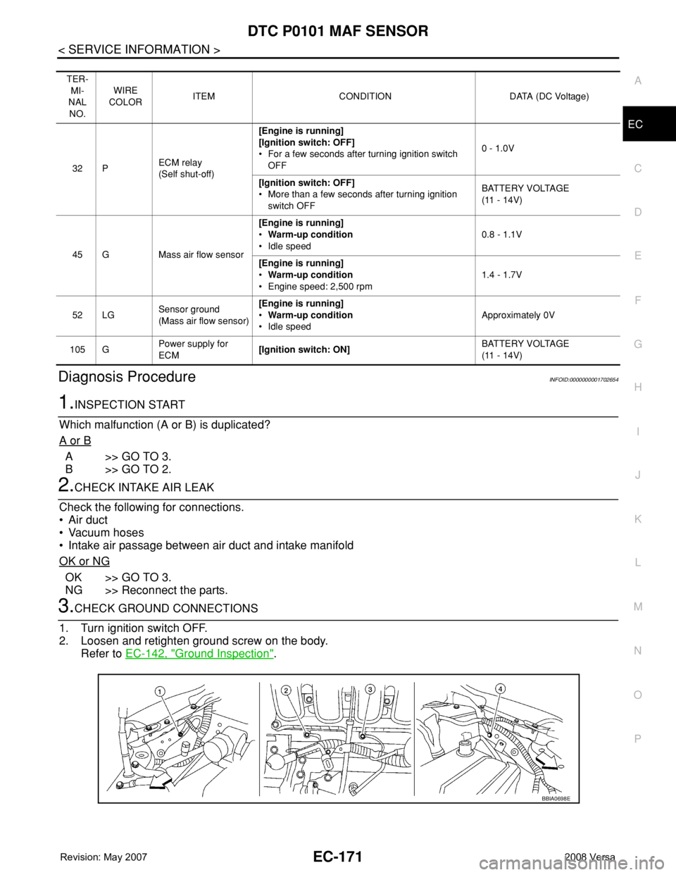
3.CHECK GROUND CONNECTIONS
1. Turn ignition switch OFF.
2. Loosen and retighten ground screw on the body.
Refer to EC-142, "
Ground Inspection".
TER-
MI-
NAL
NO.WIRE
COLORITEM CONDITION DATA (DC Voltage)
32 PECM relay
(Self shut-off)[Engine is running]
[Ignition switch: OFF]
• For a few seconds after turning ignition switch
OFF0 - 1.0V
[Ignition switch: OFF]
• More than a few seconds after turning ignition
switch OFFBATTERY VOLTAGE
(11 - 14V)
45 G Mass air flow sensor[Engine is running]
•Warm-up condition
• Idle speed0.8 - 1.1V
[Engine is running]
•Warm-up condition
• Engine speed: 2,500 rpm1.4 - 1.7V
52 LGSensor ground
(Mass air flow sensor)[Engine is running]
•Warm-up condition
• Idle speedApproximately 0V
105 GPower supply for
ECM[Ignition switch: ON]BATTERY VOLTAGE
(11 - 14V)
BBIA0698E
Page 1252 of 2771

EC-178
< SERVICE INFORMATION >
DTC P0102, P0103 MAF SENSOR
Diagnosis Procedure
INFOID:0000000001702662
1.INSPECTION START
Which malfunction (P0102 or P0103) is duplicated?
P0102 or P0103
P0102 >> GO TO 2.
P0103 >> GO TO 3.
2.CHECK INTAKE SYSTEM
Check the following for connection.
• Air duct
• Vacuum hoses
• Intake air passage between air duct and intake manifold
OK or NG
OK >> GO TO 3.
NG >> Reconnect the parts.
3.CHECK GROUND CONNECTIONS
1. Turn ignition switch OFF.
2. Loosen and retighten ground screw on the body.
Refer to EC-142, "
Ground Inspection".
TER-
MI-
NAL
NO.WIRE
COLORITEM CONDITION DATA (DC Voltage)
32 PECM relay
(Self shut-off)[Engine is running]
[Ignition switch: OFF]
• For a few seconds after turning ignition
switch OFF0 - 1.0V
[Ignition switch: OFF]
• More than a few seconds after turning igni-
tion switch OFFBATTERY VOLTAGE
(11 - 14V)
45 G Mass air flow sensor[Engine is running]
•Warm-up condition
• Idle speed0.8 - 1.1V
[Engine is running]
•Warm-up condition
• Engine speed: 2,500 rpm1.4 - 1.7V
52 LGSensor ground
(Mass air flow sensor)[Engine is running]
•Warm-up condition
• Idle speedApproximately 0V
105 G Power supply for ECM[Ignition switch: ON]BATTERY VOLTAGE
(11 - 14V)
BBIA0698E
Page 1402 of 2771
EC-328
< SERVICE INFORMATION >
DTC P0443 EVAP CANISTER PURGE VOLUME CONTROL SOLENOID VALVE
Do not use ECM ground terminals when measuring input/output voltage. Doing so may result in dam-
age to the ECM's transistor. Use a ground other than ECM terminals, such as the ground.
: Average voltage for pulse signal (Actual pulse signal can be confirmed by oscilloscope.)
Diagnosis ProcedureINFOID:0000000001702833
1.CHECK EVAP CANISTER PURGE VOLUME CONTROL SOLENOID VALVE POWER SUPPLY CIRCUIT
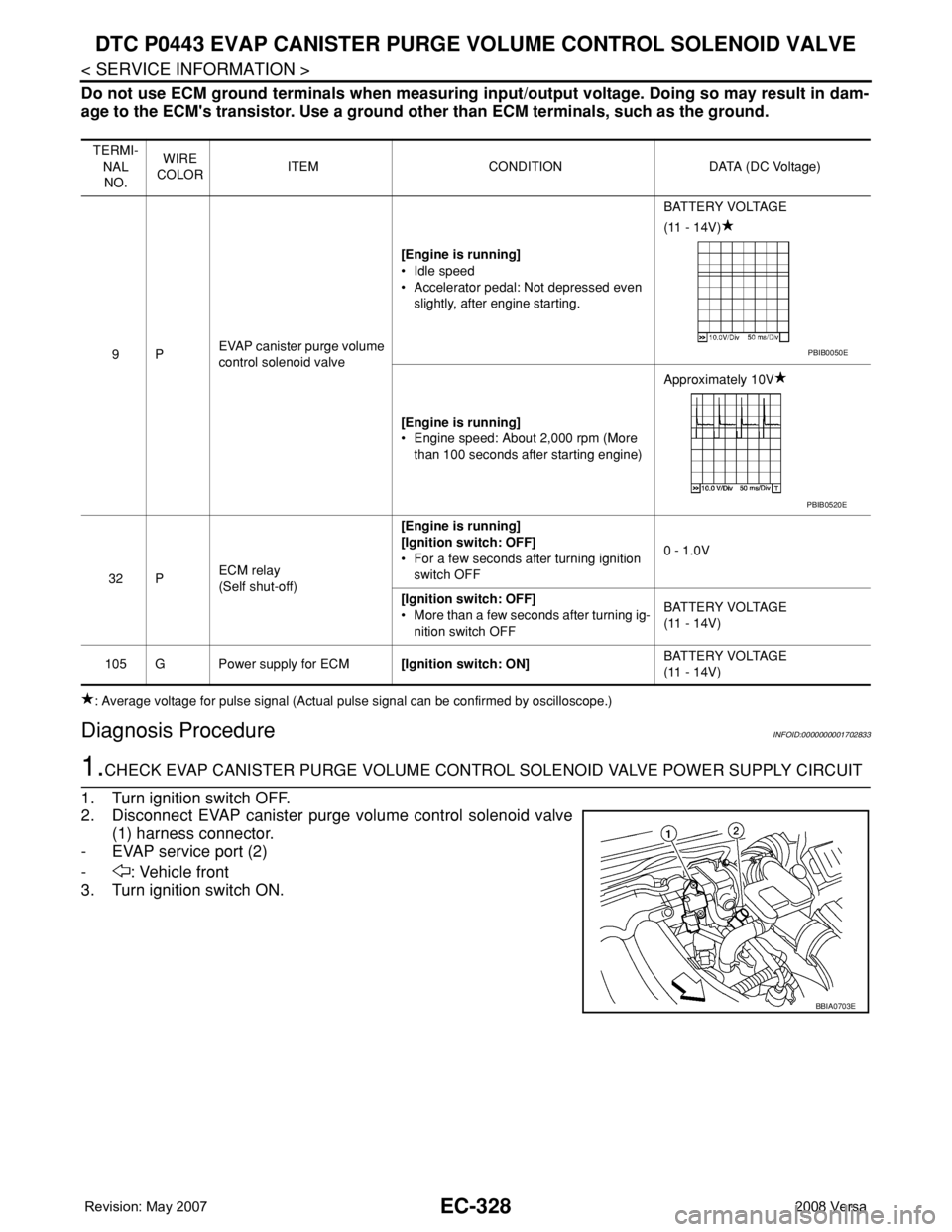
1. Turn ignition switch OFF.
2. Disconnect EVAP canister purge volume control solenoid valve
(1) harness connector.
- EVAP service port (2)
- : Vehicle front
3. Turn ignition switch ON.
TERMI-
NAL
NO.WIRE
COLORITEM CONDITION DATA (DC Voltage)
9PEVAP canister purge volume
control solenoid valve[Engine is running]
• Idle speed
• Accelerator pedal: Not depressed even
slightly, after engine starting.BATTERY VOLTAGE
(11 - 14V)
[Engine is running]
• Engine speed: About 2,000 rpm (More
than 100 seconds after starting engine)Approximately 10V
32 PECM relay
(Self shut-off)[Engine is running]
[Ignition switch: OFF]
• For a few seconds after turning ignition
switch OFF0 - 1.0V
[Ignition switch: OFF]
• More than a few seconds after turning ig-
nition switch OFFBATTERY VOLTAGE
(11 - 14V)
105 G Power supply for ECM[Ignition switch: ON]BATTERY VOLTAGE
(11 - 14V)
PBIB0050E
PBIB0520E
BBIA0703E
Page 1409 of 2771
DTC P0444, P0445 EVAP CANISTER PURGE VOLUME CONTROL SOLENOID
VALVE
EC-335
< SERVICE INFORMATION >
C
D
E
F
G
H
I
J
K
L
MA
EC
N
P O
Do not use ECM ground terminals when measuring input/output voltage. Doing so may result in dam-
age to the ECM's transistor. Use a ground other than ECM terminals, such as the ground.
: Average voltage for pulse signal (Actual pulse signal can be confirmed by oscilloscope.)
Diagnosis ProcedureINFOID:0000000001702841
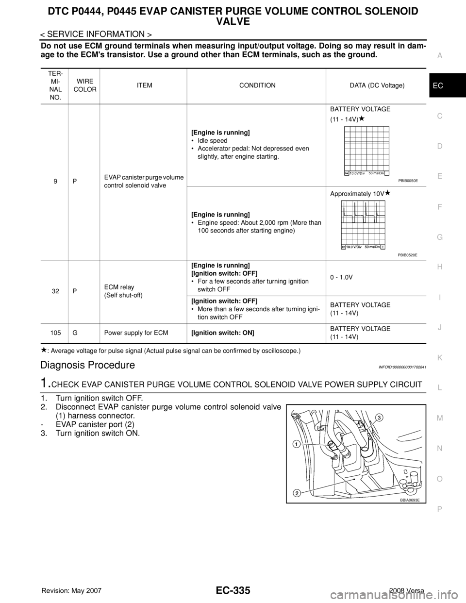
1.CHECK EVAP CANISTER PURGE VOLUME CONTROL SOLENOID VALVE POWER SUPPLY CIRCUIT
1. Turn ignition switch OFF.
2. Disconnect EVAP canister purge volume control solenoid valve
(1) harness connector.
- EVAP canister port (2)
3. Turn ignition switch ON.
TER-
MI-
NAL
NO.WIRE
COLORITEM CONDITION DATA (DC Voltage)
9PEVAP canister purge volume
control solenoid valve[Engine is running]
• Idle speed
• Accelerator pedal: Not depressed even
slightly, after engine starting.BATTERY VOLTAGE
(11 - 14V)
[Engine is running]
• Engine speed: About 2,000 rpm (More than
100 seconds after starting engine)Approximately 10V
32 PECM relay
(Self shut-off)[Engine is running]
[Ignition switch: OFF]
• For a few seconds after turning ignition
switch OFF0 - 1.0V
[Ignition switch: OFF]
• More than a few seconds after turning igni-
tion switch OFFBATTERY VOLTAGE
(11 - 14V)
105 G Power supply for ECM[Ignition switch: ON]BATTERY VOLTAGE
(11 - 14V)
PBIB0050E
PBIB0520E
BBIA0693E
Page 1415 of 2771
DTC P0447 EVAP CANISTER VENT CONTROL VALVE
EC-341
< SERVICE INFORMATION >
C
D
E
F
G
H
I
J
K
L
MA
EC
N
P O
Diagnosis ProcedureINFOID:0000000001702849
1.INSPECTION START
1. Do you have CONSULT-II?
Ye s o r N o
Yes >> GO TO 2.
No >> GO TO 3.
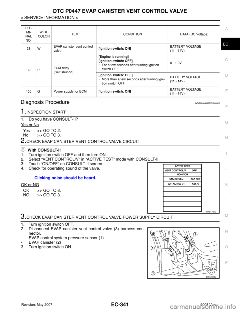
2.CHECK EVAP CANISTER VENT CONTROL VALVE CIRCUIT
With CONSULT-II
1. Turn ignition switch OFF and then turn ON.
2. Select “VENT CONTROL/V” in “ACTIVE TEST” mode with CONSULT-II.
3. Touch “ON/OFF” on CONSULT-II screen.
4. Check for operating sound of the valve.
OK or NG
OK >> GO TO 8.
NG >> GO TO 3.
3.CHECK EVAP CANISTER VENT CONTROL VALVE POWER SUPPLY CIRCUIT
1. Turn ignition switch OFF.
2. Disconnect EVAP canister vent control valve (3) harness con-
nector.
- EVAP control system pressure sensor (1)
- EVAP canister (2)
3. Turn ignition switch ON.
TER-
MI-
NAL
NO.WIRE
COLORITEM CONDITION DATA (DC Voltage)
28 WEVAP canister vent control
valve[Ignition switch: ON]BATTERY VOLTAGE
(11 - 14V)
32 PECM relay
(Self shut-off)[Engine is running]
[Ignition switch: OFF]
• For a few seconds after turning ignition
switch OFF0 - 1.0V
[Ignition switch: OFF]
• More than a few seconds after turning igni-
tion switch OFFBATTERY VOLTAGE
(11 - 14V)
105 G Power supply for ECM[Ignition switch: ON]BATTERY VOLTAGE
(11 - 14V)
Clicking noise should be heard.
PBIB1787E
BBIA0693E