2008 NISSAN LATIO relay
[x] Cancel search: relayPage 845 of 2771
CVT-6
< SERVICE INFORMATION >
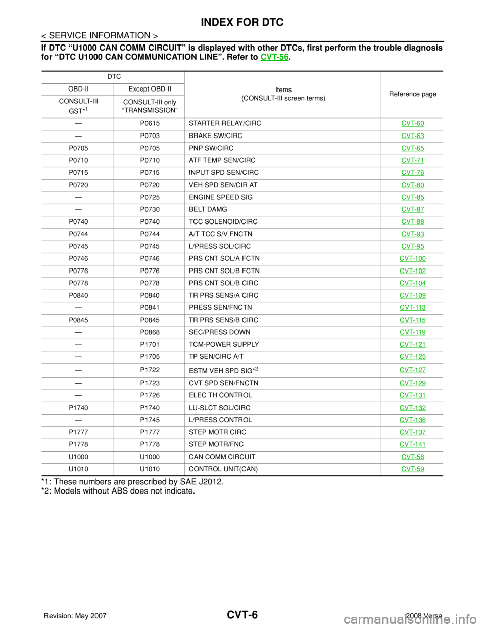
INDEX FOR DTC
If DTC “U1000 CAN COMM CIRCUIT” is displayed with other DTCs, first perform the trouble diagnosis
for “DTC U1000 CAN COMMUNICATION LINE”. Refer to CVT-56
.
*1: These numbers are prescribed by SAE J2012.
*2: Models without ABS does not indicate.
DTC
Items
(CONSULT-III screen terms)Reference page OBD-II Except OBD-II
CONSULT-III
GST*
1CONSULT-III only
“TRANSMISSION”
— P0615 STARTER RELAY/CIRCCVT-60
— P0703 BRAKE SW/CIRCCVT-63
P0705 P0705 PNP SW/CIRCCVT-65
P0710 P0710 ATF TEMP SEN/CIRCCVT-71
P0715 P0715 INPUT SPD SEN/CIRCCVT-76
P0720 P0720 VEH SPD SEN/CIR ATCVT-80
— P0725 ENGINE SPEED SIGCVT-85
— P0730 BELT DAMGCVT-87
P0740 P0740 TCC SOLENOID/CIRCCVT-88
P0744 P0744 A/T TCC S/V FNCTNCVT-93
P0745 P0745 L/PRESS SOL/CIRCCVT-95
P0746 P0746 PRS CNT SOL/A FCTNCVT-100
P0776 P0776 PRS CNT SOL/B FCTNCVT-102
P0778 P0778 PRS CNT SOL/B CIRCCVT-104
P0840 P0840 TR PRS SENS/A CIRCCVT-109
— P0841 PRESS SEN/FNCTNCVT-113
P0845 P0845 TR PRS SENS/B CIRCCVT-115
— P0868 SEC/PRESS DOWNCVT-119
— P1701 TCM-POWER SUPPLYCVT-121
— P1705 TP SEN/CIRC A/TCVT-125
— P1722
ESTM VEH SPD SIG*2CVT-127
— P1723 CVT SPD SEN/FNCTNCVT-129
— P1726 ELEC TH CONTROLCVT-131
P1740 P1740 LU-SLCT SOL/CIRCCVT-132
— P1745 L/PRESS CONTROLCVT-136
P1777 P1777 STEP MOTR CIRCCVT-137
P1778 P1778 STEP MOTR/FNCCVT-141
U1000 U1000 CAN COMM CIRCUITCVT-56
U1010 U1010 CONTROL UNIT(CAN)CVT-59
Page 859 of 2771
CVT-20
< SERVICE INFORMATION >
CVT SYSTEM
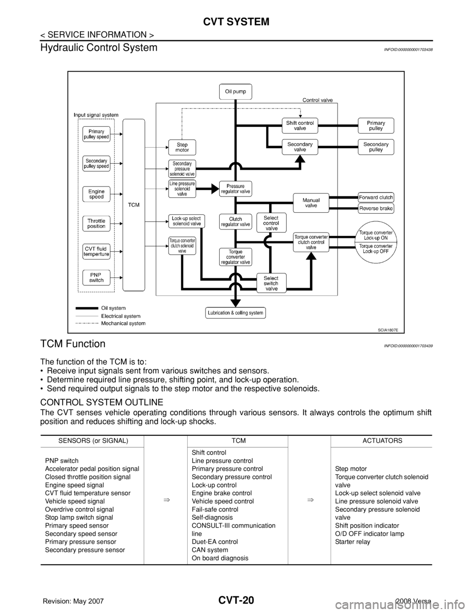
Hydraulic Control System
INFOID:0000000001703438
TCM FunctionINFOID:0000000001703439
The function of the TCM is to:
• Receive input signals sent from various switches and sensors.
• Determine required line pressure, shifting point, and lock-up operation.
• Send required output signals to the step motor and the respective solenoids.
CONTROL SYSTEM OUTLINE
The CVT senses vehicle operating conditions through various sensors. It always controls the optimum shift
position and reduces shifting and lock-up shocks.
SCIA1807E
SENSORS (or SIGNAL)
⇒TCM
⇒ACTUATORS
PNP switch
Accelerator pedal position signal
Closed throttle position signal
Engine speed signal
CVT fluid temperature sensor
Vehicle speed signal
Overdrive control signal
Stop lamp switch signal
Primary speed sensor
Secondary speed sensor
Primary pressure sensor
Secondary pressure sensorShift control
Line pressure control
Primary pressure control
Secondary pressure control
Lock-up control
Engine brake control
Vehicle speed control
Fail-safe control
Self-diagnosis
CONSULT-III communication
line
Duet-EA control
CAN system
On board diagnosisSte p m ot or
Torque converter clutch solenoid
valve
Lock-up select solenoid valve
Line pressure solenoid valve
Secondary pressure solenoid
valve
Shift position indicator
O/D OFF indicator lamp
Starter relay
Page 885 of 2771

CVT-46
< SERVICE INFORMATION >
TROUBLE DIAGNOSIS
4BRLock-up select
solenoid valveSelector lever in “P” and “N” positions Battery voltage
Wait at least for 5 seconds with the selector lever in
“R”, “D” and “L” positions0 V
5 L CAN-H — —
6 P CAN-L — —
8VBack-up lamp
relaySelector lever in “R” position. 0 V
Selector lever in other positions. Battery voltage
10 R Power supply— Battery voltage
—0 V
11 L Step motor A Within 2 seconds after ignition switch ON, the time measurement by using
the pulse width measurement function (Hi level) of CONSULT-III.*1
*1: A circuit tester cannot be used to test this item.30.0 msec
12 Y Step motor B10.0 msec
13 G ROM assembly — —
14 Y ROM assembly — —
15 G ROM assembly — —
19 R Power supply— Battery voltage
—0 V
20 W Step motor C Within 2 seconds after ignition switch ON, the time measurement by using
the pulse width measurement function (Hi level) of CONSULT-III.*1
*1: A circuit tester cannot be used to test this item.30.0 msec
21 P Step motor D10.0 msec
24 BR Starter relaySelector lever in “N” and “P”positions. Battery voltage
Selector lever in other positions. 0 V
25 B Ground Always 0 V
27 GR PNP switch 1Selector lever in “R”, “N” and “D” positions. 0 V
Selector lever in “P” and “L” positions. Battery voltage
28 YPower supply
(memory back-
up)Always Battery voltage
29 ROutput speed
sensor (Second-
ary speed sen-
sor)When driving [“D” position, 20 km/h (12 MPH)]. 570 Hz
31 LG K-LINE — — Te r m i n a lWire
colorItem Condition Data (Approx.)
Page 889 of 2771
CVT-50
< SERVICE INFORMATION >
TROUBLE DIAGNOSIS
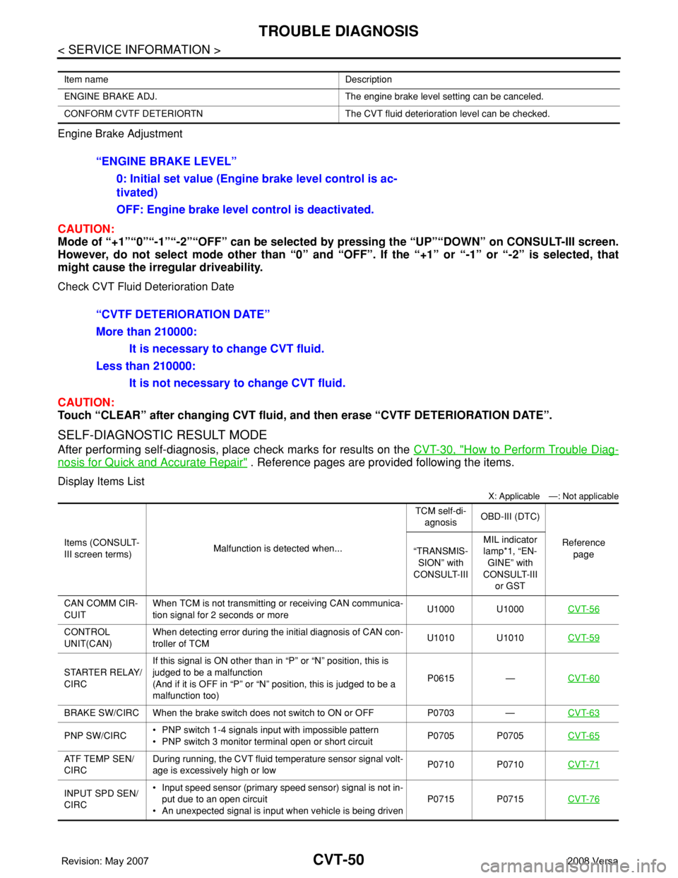
Engine Brake Adjustment
CAUTION:
Mode of “+1”“0”“-1”“-2”“OFF” can be selected by pressing the “UP”“DOWN” on CONSULT-III screen.
However, do not select mode other than “0” and “OFF”. If the “+1” or “-1” or “-2” is selected, that
might cause the irregular driveability.
Check CVT Fluid Deterioration Date
CAUTION:
Touch “CLEAR” after changing CVT fluid, and then erase “CVTF DETERIORATION DATE”.
SELF-DIAGNOSTIC RESULT MODE
After performing self-diagnosis, place check marks for results on the CVT-30, "How to Perform Trouble Diag-
nosis for Quick and Accurate Repair" . Reference pages are provided following the items.
Display Items List
X: Applicable —: Not applicable
Item name Description
ENGINE BRAKE ADJ. The engine brake level setting can be canceled.
CONFORM CVTF DETERIORTN The CVT fluid deterioration level can be checked.
“ENGINE BRAKE LEVEL”
0: Initial set value (Engine brake level control is ac-
tivated)
OFF: Engine brake level control is deactivated.
“CVTF DETERIORATION DATE”
More than 210000:
It is necessary to change CVT fluid.
Less than 210000:
It is not necessary to change CVT fluid.
Items (CONSULT-
III screen terms)Malfunction is detected when...TCM self-di-
agnosisOBD-III (DTC)
Reference
page “TRANSMIS-
SION” with
CONSULT-IIIMIL indicator
lamp*1, “EN-
GINE” with
CONSULT-III
or GST
CAN COMM CIR-
CUITWhen TCM is not transmitting or receiving CAN communica-
tion signal for 2 seconds or moreU1000 U1000CVT-56
CONTROL
UNIT(CAN)When detecting error during the initial diagnosis of CAN con-
troller of TCMU1010 U1010CVT-59
STARTER RELAY/
CIRCIf this signal is ON other than in “P” or “N” position, this is
judged to be a malfunction
(And if it is OFF in “P” or “N” position, this is judged to be a
malfunction too)P0615 —CVT-60
BRAKE SW/CIRC When the brake switch does not switch to ON or OFF P0703 —CVT-63
PNP SW/CIRC• PNP switch 1-4 signals input with impossible pattern
• PNP switch 3 monitor terminal open or short circuitP0705 P0705CVT-65
ATF TEMP SEN/
CIRCDuring running, the CVT fluid temperature sensor signal volt-
age is excessively high or lowP0710 P0710CVT-71
INPUT SPD SEN/
CIRC• Input speed sensor (primary speed sensor) signal is not in-
put due to an open circuit
• An unexpected signal is input when vehicle is being drivenP0715 P0715CVT-76
Page 893 of 2771

CVT-54
< SERVICE INFORMATION >
TROUBLE DIAGNOSIS
FULL SW (ON/OFF) X X
Signal input with CAN communications
IDLE SW (ON/OFF) X X
SPORT MODE SW (ON/OFF) X XOverdrive control switch (Signal input with CAN
comunication)
STRDWNSW (ON/OFF) X —
Not mounted but displayed. STRUPSW (ON/OFF) X —
DOWNLVR (ON/OFF) X —
UPLVR (ON/OFF) X —
NONMMODE (ON/OFF) X —
MMODE (ON/OFF) X —
INDLRNG (ON/OFF) — — “L” position indicator output
INDDRNG (ON/OFF) — — “D” position indicator output
INDNRNG (ON/OFF) — — “N” position indicator output
INDRRNG (ON/OFF) — — “R” position indicator output
INDPRNG (ON/OFF) — — “P” position indicator output
CVT LAMP (ON/OFF) — —
SPORT MODE IND (ON/OFF) — —
MMODE IND (ON/OFF) — — Not mounted but displayed.
SMCOIL D (ON/OFF) — — Step motor coil “D” energizing status
SMCOIL C (ON/OFF) — — Step motor coil “C” energizing status
SMCOIL B (ON/OFF) — — Step motor coil “B” energizing status
SMCOIL A (ON/OFF) — — Step motor coil “A” energizing status
LUSEL SOL OUT (ON/OFF) — —
REV LAMP (ON/OFF) — X
STRTR RLY OUT (ON/OFF) — — Starter relay
LUSEL SOL MON (ON/OFF) — —
STRTR RLY MON (ON/OFF) — — Starter relay
VDC ON (ON/OFF) X —
Not mounted but displayed.
TCS ON (ON/OFF) X —
ABS ON (ON/OFF) X —
ACC ON (ON/OFF) X — Not mounted but displayed.
RANGE — XIndicates position is recognized by TCM. Indi-
cates a specific value required for control when
fail-safe function is activated.
M GEAR POS — X
Voltage (V) — —Displays the value measured by the voltage
probe. Monitored item (Unit)Monitor item selection
Remarks ECU IN-
PUT SIG-
NALSMAIN SIG-
NALSSELEC-
TION
FROM
MENU
Page 899 of 2771
CVT-60
< SERVICE INFORMATION >
DTC P0615 START SIGNAL CIRCUIT
DTC P0615 START SIGNAL CIRCUIT
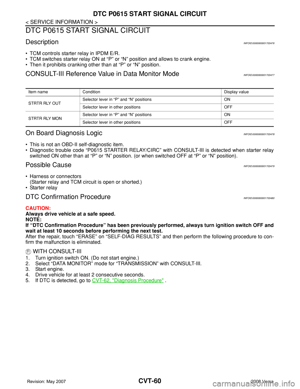
DescriptionINFOID:0000000001703476
• TCM controls starter relay in IPDM E/R.
• TCM switches starter relay ON at “P” or “N” position and allows to crank engine.
• Then it prohibits cranking other than at “P” or “N” position.
CONSULT-III Reference Value in Data Monitor ModeINFOID:0000000001703477
On Board Diagnosis LogicINFOID:0000000001703478
• This is not an OBD-II self-diagnostic item.
• Diagnostic trouble code “P0615 STARTER RELAY/CIRC” with CONSULT-III is detected when starter relay
switched ON other than at “P” or “N” position. (or when switched OFF at “P” or “N” position).
Possible CauseINFOID:0000000001703479
• Harness or connectors
(Starter relay and TCM circuit is open or shorted.)
• Starter relay
DTC Confirmation ProcedureINFOID:0000000001703480
CAUTION:
Always drive vehicle at a safe speed.
NOTE:
If “DTC Confirmation Procedure” has been previously performed, always turn ignition switch OFF and
wait at least 10 seconds before performing the next test.
After the repair, touch “ERASE” on “SELF-DIAG RESULTS” and then perform the following procedure to con-
firm the malfunction is eliminated.
WITH CONSULT-III
1. Turn ignition switch ON. (Do not start engine.)
2. Select “DATA MONITOR” mode for “TRANSMISSION” with CONSULT-III.
3. Start engine.
4. Drive vehicle for at least 2 consecutive seconds.
5. If DTC is detected, go to CVT-62, "
Diagnosis Procedure" .
Item name Condition Display value
STRTR RLY OUTSelector lever in “P” and “N” positions ON
Selector lever in other positions OFF
STRTR RLY MONSelector lever in “P” and “N” positions ON
Selector lever in other positions OFF
Page 901 of 2771
CVT-62
< SERVICE INFORMATION >
DTC P0615 START SIGNAL CIRCUIT
Diagnosis Procedure
INFOID:0000000001703482
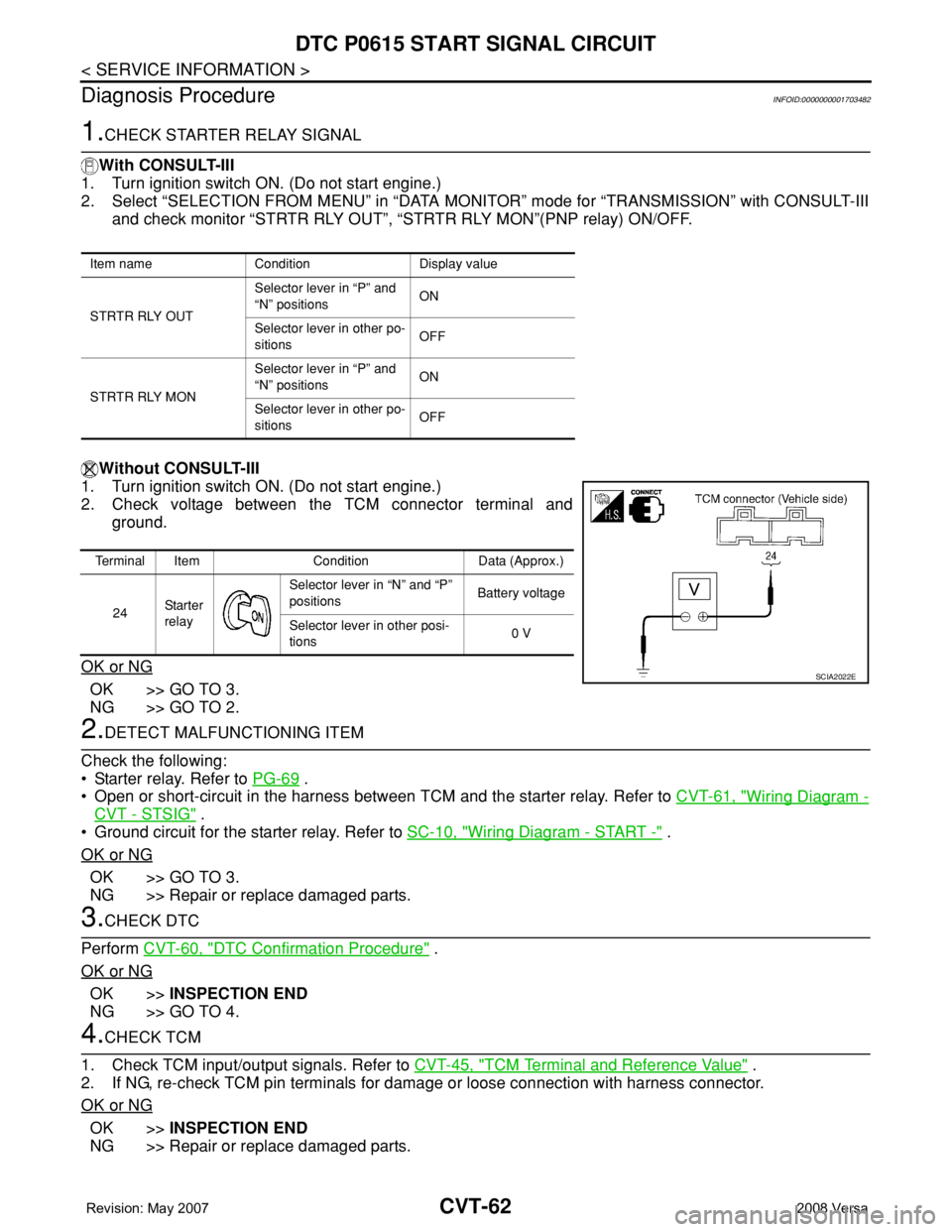
1.CHECK STARTER RELAY SIGNAL
With CONSULT-III
1. Turn ignition switch ON. (Do not start engine.)
2. Select “SELECTION FROM MENU” in “DATA MONITOR” mode for “TRANSMISSION” with CONSULT-III
and check monitor “STRTR RLY OUT”, “STRTR RLY MON”(PNP relay) ON/OFF.
Without CONSULT-III
1. Turn ignition switch ON. (Do not start engine.)
2. Check voltage between the TCM connector terminal and
ground.
OK or NG
OK >> GO TO 3.
NG >> GO TO 2.
2.DETECT MALFUNCTIONING ITEM
Check the following:
• Starter relay. Refer to PG-69
.
• Open or short-circuit in the harness between TCM and the starter relay. Refer to CVT-61, "
Wiring Diagram -
CVT - STSIG" .
• Ground circuit for the starter relay. Refer to SC-10, "
Wiring Diagram - START -" .
OK or NG
OK >> GO TO 3.
NG >> Repair or replace damaged parts.
3.CHECK DTC
Perform CVT-60, "
DTC Confirmation Procedure" .
OK or NG
OK >>INSPECTION END
NG >> GO TO 4.
4.CHECK TCM
1. Check TCM input/output signals. Refer to CVT-45, "
TCM Terminal and Reference Value" .
2. If NG, re-check TCM pin terminals for damage or loose connection with harness connector.
OK or NG
OK >>INSPECTION END
NG >> Repair or replace damaged parts.
Item name Condition Display value
STRTR RLY OUTSelector lever in “P” and
“N” positionsON
Selector lever in other po-
sitionsOFF
STRTR RLY MONSelector lever in “P” and
“N” positionsON
Selector lever in other po-
sitionsOFF
Terminal Item Condition Data (Approx.)
24Sta r te r
relaySelector lever in “N” and “P”
positionsBattery voltage
Selector lever in other posi-
tions0 V
SCIA2022E
Page 1080 of 2771

EC-6
Overall Function Check .........................................406
Wiring Diagram ......................................................407
Diagnosis Procedure .............................................408
DTC P1148 CLOSED LOOP CONTROL .........411
On Board Diagnosis Logic .....................................411
DTC P1217 ENGINE OVER TEMPERATURE .412
System Description ................................................412
CONSULT-II Reference Value in Data Monitor
Mode ......................................................................
413
On Board Diagnosis Logic .....................................413
Overall Function Check .........................................413
Wiring Diagram ......................................................416
Diagnosis Procedure .............................................417
Main 13 Causes of Overheating ............................424
Component Inspection ...........................................424
DTC P1225 TP SENSOR .................................426
Component Description .........................................426
On Board Diagnosis Logic .....................................426
DTC Confirmation Procedure ................................426
Diagnosis Procedure .............................................426
Removal and Installation .......................................427
DTC P1226 TP SENSOR .................................428
Component Description .........................................428
On Board Diagnosis Logic .....................................428
DTC Confirmation Procedure ................................428
Diagnosis Procedure .............................................428
Removal and Installation .......................................429
DTC P1421 COLD START CONTROL ............430
Description .............................................................430
On Board Diagnosis Logic .....................................430
DTC Confirmation Procedure ................................430
Diagnosis Procedure .............................................430
DTC P1564 ASCD STEERING SWITCH .........432
Component Description .........................................432
CONSULT-II Reference Value in Data Monitor
Mode ......................................................................
432
On Board Diagnosis Logic .....................................432
DTC Confirmation Procedure ................................433
Wiring Diagram ......................................................434
Diagnosis Procedure .............................................435
Component Inspection ...........................................437
DTC P1572 ASCD BRAKE SWITCH ..............438
Component Description .........................................438
CONSULT-II Reference Value in Data Monitor
Mode ......................................................................
438
On Board Diagnosis Logic .....................................438
DTC Confirmation Procedure ................................439
Wiring Diagram ......................................................440
Diagnosis Procedure .............................................441
Component Inspection ...........................................445
DTC P1574 ASCD VEHICLE SPEED SEN-
SOR ..................................................................
447
Component Description .........................................447
On Board Diagnosis Logic ....................................447
DTC Confirmation Procedure ................................447
Diagnosis Procedure .............................................448
DTC P1715 INPUT SPEED SENSOR (TUR-
BINE REVOLUTION SENSOR) ........................
449
Description ............................................................449
CONSULT-II Reference Value in Data Monitor
Mode .....................................................................
449
On Board Diagnosis Logic ....................................449
Diagnosis Procedure .............................................449
DTC P1715 INPUT SPEED SENSOR (PRIMA-
RY SPEED SENSOR) .......................................
450
Description ............................................................450
CONSULT-II Reference Value in Data Monitor
Mode .....................................................................
450
On Board Diagnosis Logic ....................................450
DTC Confirmation Procedure ................................450
Diagnosis Procedure .............................................451
DTC P1805 BRAKE SWITCH ..........................452
Description ............................................................452
CONSULT-II Reference Value in Data Monitor
Mode .....................................................................
452
On Board Diagnosis Logic ....................................452
DTC Confirmation Procedure ................................452
Wiring Diagram .....................................................453
Diagnosis Procedure .............................................454
Component Inspection ..........................................455
DTC P2100, P2103 THROTTLE CONTROL
MOTOR RELAY ................................................
456
Component Description ........................................456
CONSULT-II Reference Value in Data Monitor
Mode .....................................................................
456
On Board Diagnosis Logic ....................................456
DTC Confirmation Procedure ................................456
Wiring Diagram .....................................................458
Diagnosis Procedure .............................................459
DTC P2101 ELECTRIC THROTTLE CON-
TROL FUNCTION .............................................
461
Description ............................................................461
On Board Diagnosis Logic ....................................461
DTC Confirmation Procedure ................................461
Wiring Diagram .....................................................462
Diagnosis Procedure .............................................463
Component Inspection ..........................................466
Removal and Installation .......................................466
DTC P2118 THROTTLE CONTROL MOTOR ..467
Component Description ........................................467
On Board Diagnosis Logic ....................................467
DTC Confirmation Procedure ................................467
Wiring Diagram .....................................................468
Diagnosis Procedure .............................................469
Component Inspection ..........................................470
Removal and Installation .......................................470