2008 NISSAN LATIO charging
[x] Cancel search: chargingPage 2420 of 2771
MTC-82
< SERVICE INFORMATION >
REFRIGERANT LINES
INSTALLATION
Installation is in the reverse order of removal.
CAUTION:
• Replace O-rings of refrigerant pressure sensor with a new one, and apply compressor oil when
installing.
• When recharging refrigerant, check for leaks.
Removal and Installation of CondenserINFOID:0000000001704329
REMOVAL
1. Remove the three upper headlamp bolts to reposition the headlamps out of the way
2. Remove the radiator core support upper. Refer to BL-19
.
3. Remove high-pressure flexible hose and high-pressure pipe from condenser. Refer to MTC-80, "
Removal
and Installation of High-pressure Flexible Hose" and MTC-81, "Removal and Installation of High-pres-
sure Pipe" .
CAUTION:
Cap or wrap the joint of the pipe with suitable material such as vinyl tape to avoid the entry of air.
4. Disconnect refrigerant pressure sensor connector.
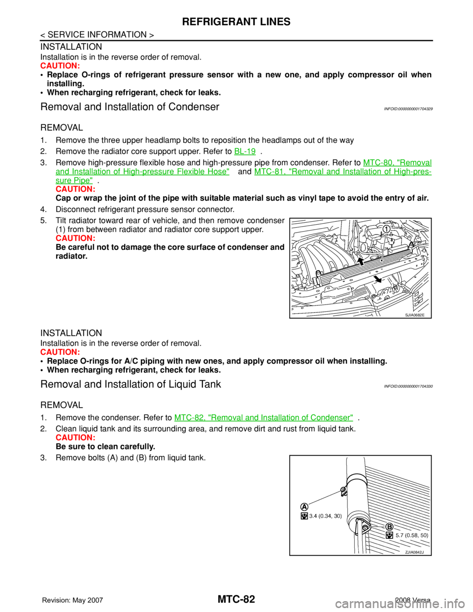
5. Tilt radiator toward rear of vehicle, and then remove condenser
(1) from between radiator and radiator core support upper.
CAUTION:
Be careful not to damage the core surface of condenser and
radiator.
INSTALLATION
Installation is in the reverse order of removal.
CAUTION:
• Replace O-rings for A/C piping with new ones, and apply compressor oil when installing.
• When recharging refrigerant, check for leaks.
Removal and Installation of Liquid TankINFOID:0000000001704330
REMOVAL
1. Remove the condenser. Refer to MTC-82, "Removal and Installation of Condenser" .
2. Clean liquid tank and its surrounding area, and remove dirt and rust from liquid tank.
CAUTION:
Be sure to clean carefully.
3. Remove bolts (A) and (B) from liquid tank.
SJIA0682E
ZJIA0842J
Page 2421 of 2771
REFRIGERANT LINES
MTC-83
< SERVICE INFORMATION >
C
D
E
F
G
H
I
K
L
MA
B
MTC
N
O
P
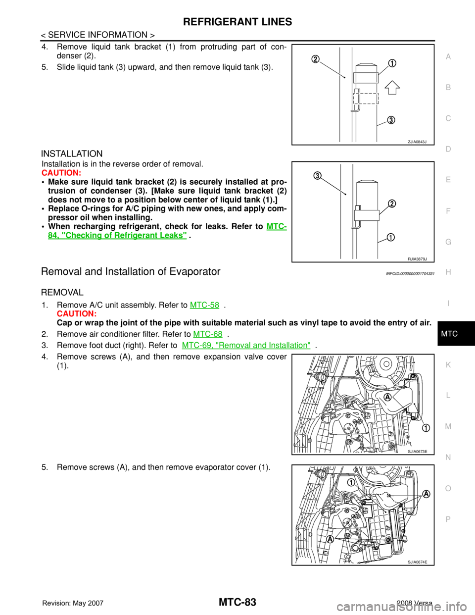
4. Remove liquid tank bracket (1) from protruding part of con-
denser (2).
5. Slide liquid tank (3) upward, and then remove liquid tank (3).
INSTALLATION
Installation is in the reverse order of removal.
CAUTION:
• Make sure liquid tank bracket (2) is securely installed at pro-
trusion of condenser (3). [Make sure liquid tank bracket (2)
does not move to a position below center of liquid tank (1).]
• Replace O-rings for A/C piping with new ones, and apply com-
pressor oil when installing.
• When recharging refrigerant, check for leaks. Refer to MTC-
84, "Checking of Refrigerant Leaks" .
Removal and Installation of EvaporatorINFOID:0000000001704331
REMOVAL
1. Remove A/C unit assembly. Refer to MTC-58 .
CAUTION:
Cap or wrap the joint of the pipe with suitable material such as vinyl tape to avoid the entry of air.
2. Remove air conditioner filter. Refer to MTC-68
.
3. Remove foot duct (right). Refer to MTC-69, "
Removal and Installation" .
4. Remove screws (A), and then remove expansion valve cover
(1).
5. Remove screws (A), and then remove evaporator cover (1).
ZJIA0843J
RJIA3879J
SJIA0673E
SJIA0674E
Page 2422 of 2771
MTC-84
< SERVICE INFORMATION >
REFRIGERANT LINES
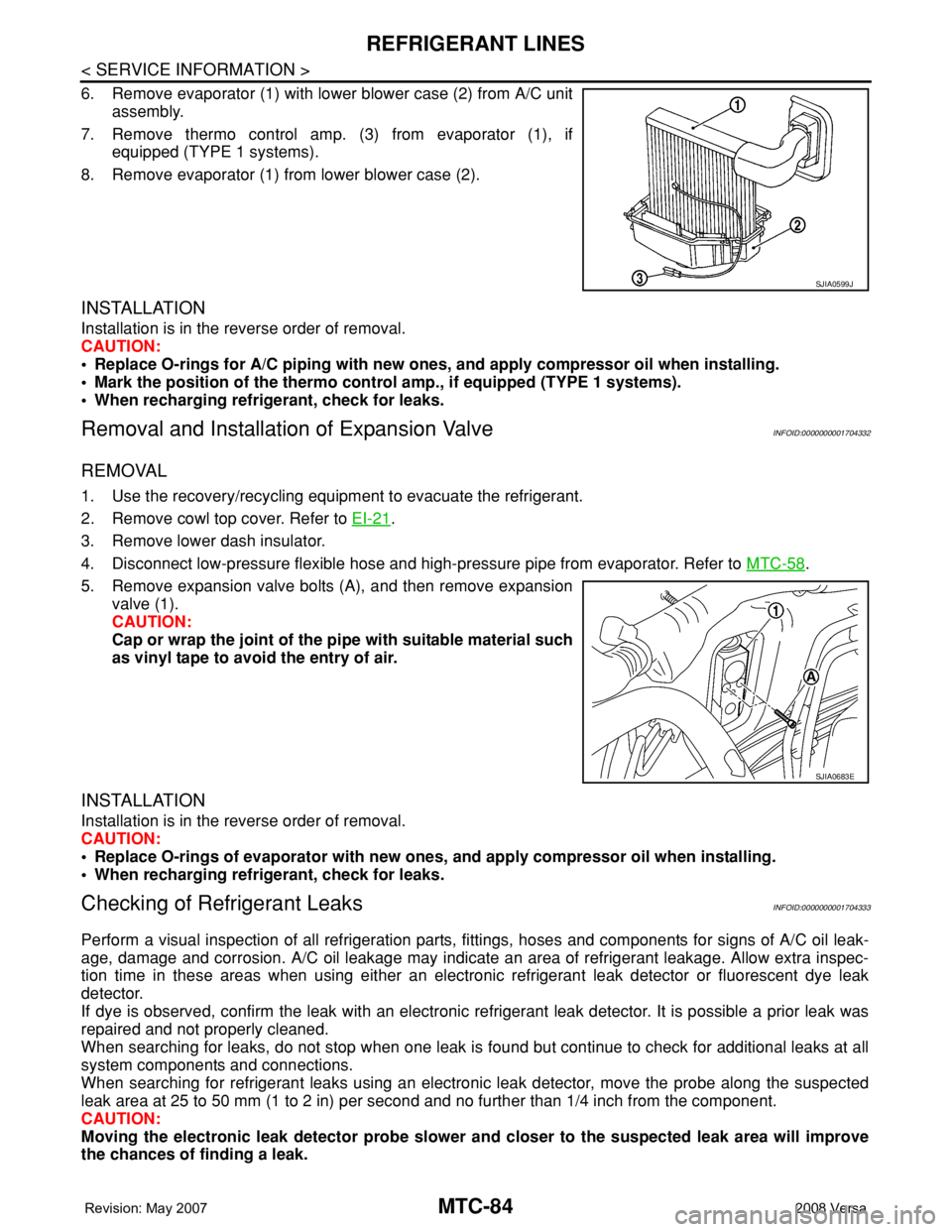
6. Remove evaporator (1) with lower blower case (2) from A/C unit
assembly.
7. Remove thermo control amp. (3) from evaporator (1), if
equipped (TYPE 1 systems).
8. Remove evaporator (1) from lower blower case (2).
INSTALLATION
Installation is in the reverse order of removal.
CAUTION:
• Replace O-rings for A/C piping with new ones, and apply compressor oil when installing.
• Mark the position of the thermo control amp., if equipped (TYPE 1 systems).
• When recharging refrigerant, check for leaks.
Removal and Installation of Expansion ValveINFOID:0000000001704332
REMOVAL
1. Use the recovery/recycling equipment to evacuate the refrigerant.
2. Remove cowl top cover. Refer to EI-21
.
3. Remove lower dash insulator.
4. Disconnect low-pressure flexible hose and high-pressure pipe from evaporator. Refer to MTC-58
.
5. Remove expansion valve bolts (A), and then remove expansion
valve (1).
CAUTION:
Cap or wrap the joint of the pipe with suitable material such
as vinyl tape to avoid the entry of air.
INSTALLATION
Installation is in the reverse order of removal.
CAUTION:
• Replace O-rings of evaporator with new ones, and apply compressor oil when installing.
• When recharging refrigerant, check for leaks.
Checking of Refrigerant LeaksINFOID:0000000001704333
Perform a visual inspection of all refrigeration parts, fittings, hoses and components for signs of A/C oil leak-
age, damage and corrosion. A/C oil leakage may indicate an area of refrigerant leakage. Allow extra inspec-
tion time in these areas when using either an electronic refrigerant leak detector or fluorescent dye leak
detector.
If dye is observed, confirm the leak with an electronic refrigerant leak detector. It is possible a prior leak was
repaired and not properly cleaned.
When searching for leaks, do not stop when one leak is found but continue to check for additional leaks at all
system components and connections.
When searching for refrigerant leaks using an electronic leak detector, move the probe along the suspected
leak area at 25 to 50 mm (1 to 2 in) per second and no further than 1/4 inch from the component.
CAUTION:
Moving the electronic leak detector probe slower and closer to the suspected leak area will improve
the chances of finding a leak.
SJIA0599J
SJIA0683E
Page 2423 of 2771
REFRIGERANT LINES
MTC-85
< SERVICE INFORMATION >
C
D
E
F
G
H
I
K
L
MA
B
MTC
N
O
P
Checking System for Leaks Using the Fluorescent Leak DetectorINFOID:0000000001704334
1. Check A/C system for leaks using the UV lamp and safety goggles J-42220 in a low sunlight area (area
without windows preferable). Illuminate all components, fittings and lines. The dye will appear as a bright
green/yellow area at the point of leakage. Fluorescent dye observed at the evaporator drain opening indi-
cates an evaporator core assembly (tubes, core or expansion valve) leak.
2. If the suspected area is difficult to see, use an adjustable mirror or wipe the area with a clean shop rag or
cloth, with the UV lamp for dye residue.
3. After the leak is repaired, remove any residual dye using dye cleaner J-43872 to prevent future misdiag-
nosis.
4. Perform a system performance check and verify the leak repair with an approved electronic refrigerant
leak detector.
NOTE:
Other gases in the work area or substances on the A/C components, for example, anti-freeze, windshield
washer fluid, solvents and oils, may falsely trigger the leak detector. Make sure the surfaces to be checked are
clean.
Clean with a dry cloth or blow off with shop air.
Do not allow the sensor tip of the detector to contact with any substance. This can also cause false readings
and may damage the detector.
Dye InjectionINFOID:0000000001704335
(This procedure is only necessary when recharging the system or when the compressor has seized and was
replaced.)
1. Check A/C system static (at rest) pressure. Pressure must be at least 345 kPa (3.45 bar, 3.52 kg/cm
2, 50
psi).
2. Pour one bottle (1/4 ounce / 7.4 cc) of the A/C refrigerant dye into the injector tool J-41459.
3. Connect the injector tool to the A/C low-pressure side service fitting.
4. Start engine and switch A/C ON.
5. When the A/C operating (compressor running), inject one bottle (1/4 ounce / 7.4 cc) of fluorescent dye
through the low-pressure service valve using dye injector tool J-41459 (refer to the manufacture’s operat-
ing instructions).
6. With the engine still running, disconnect the injector tool from the service fitting.
CAUTION:
Be careful the A/C system or replacing a component, pour the dye directly into the open system
connection and proceed with the service procedures.
7. Operate the A/C system for a minimum of 20 minutes to mix the dye with the system oil. Depending on the
leak size, operating conditions and location of the leak, it may take from minutes to days for the dye to
penetrate a leak and become visible.
Electronic Refrigerant Leak DetectorINFOID:0000000001704336
PRECAUTIONS FOR HANDLING LEAK DETECTOR
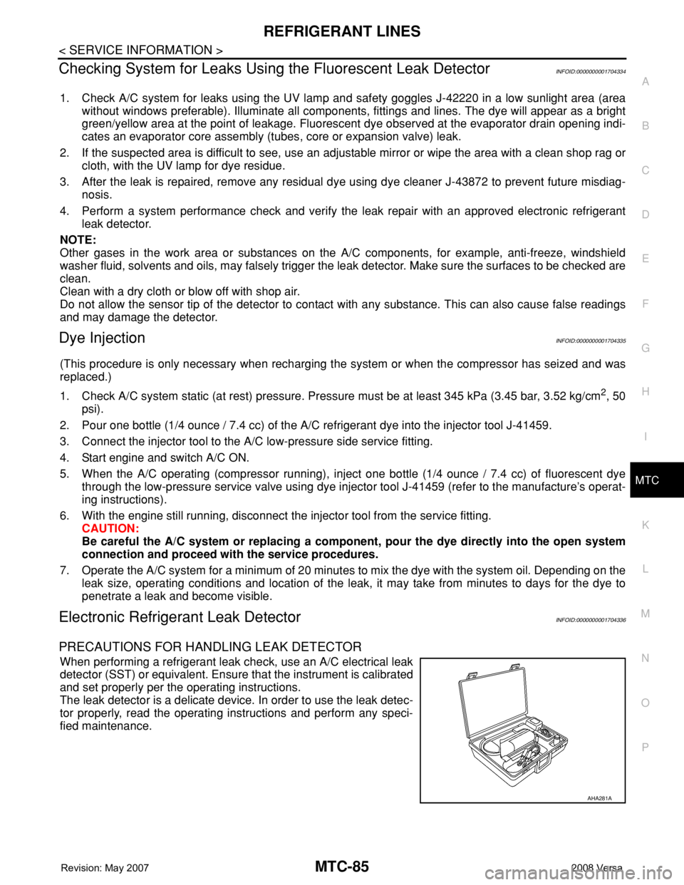
When performing a refrigerant leak check, use an A/C electrical leak
detector (SST) or equivalent. Ensure that the instrument is calibrated
and set properly per the operating instructions.
The leak detector is a delicate device. In order to use the leak detec-
tor properly, read the operating instructions and perform any speci-
fied maintenance.
AHA281A
Page 2426 of 2771
MTC-88
< SERVICE INFORMATION >
SERVICE DATA AND SPECIFICATIONS (SDS)
SERVICE DATA AND SPECIFICATIONS (SDS)
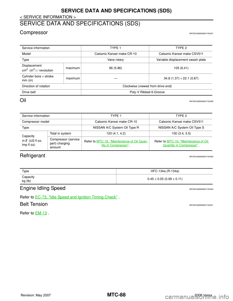
CompressorINFOID:0000000001704337
OilINFOID:0000000001704338
RefrigerantINFOID:0000000001704339
Engine Idling SpeedINFOID:0000000001704340
Refer to EC-73, "Idle Speed and Ignition Timing Check" .
Belt TensionINFOID:0000000001704341
Refer to EM-13 .
Service information TYPE 1 TYPE 2
Model Calsonic Kansei make CR-10 Calsonic Kansei make CSV511
Type Vane rotary Variable displacement swash plate
Displacement
cm
3 (in3 ) / revolutionmaximum 96 (5.86) 105 (6.41)
Cylinder bore × stroke
mm (in)maximum — 34.8 (1.37) × 22.1 (0.87)
Direction of rotation Clockwise (viewed from drive end)
Drive belt Poly-V Ribbed 6-Groove
Service information TYPE 1 TYPE 2
Compressor model Calsonic Kansei make CR-10 Calsonic Kansei make CSV511
Type NISSAN A/C System Oil Type R NISSAN A/C System Oil Type S
Capacity
m (US fl oz,
lmp fl oz)Total in system 120 (4.1, 4.2) 100 (3.4, 3.5)
Compressor (service
part) charging
amountRefer to MTC-16, "
Maintenance of Oil Quan-
tity in Compressor" .Refer to MTC-16, "
Maintenance of Oil
Quantity in Compressor" .
Ty p eHFC-134a (R-134a)
Capacity
kg (lb)0.45 ± 0.05 (0.99 ± 0.11)
Page 2491 of 2771

PG-58
< SERVICE INFORMATION >
HARNESS
Wiring Diagram Codes (Cell Codes)
INFOID:0000000001704709
Use the chart below to find out what each wiring diagram code stands for.
Refer to the wiring diagram code in the alphabetical index to find the location (page number) of each wiring
diagram.
D3 D404 W/3 : Rear wiper motor
D4 D405 W/4 : Back door lock assembly
D4 D406 W/2 : Back door request switch
E2 D407 W/2 : High mounted stop lamp
D4 D408 BR/2 : Back door opener switch
E4 D409 B/1 : Condenser-1
C2 D410 — : Body ground
E3 D411 B/1 : Condenser-1
E1 D412 B/1 : Rear window defogger (+)
C2 D413 B/1 : Rear window defogger (-)
F3 D414 — : Body ground
Code Section Wiring Diagram Name
ABS BRC Anti-lock Brake System
A/C,M MTC Manual Air Conditioner
APPS1 EC Accelerator Pedal Position Sensor
A/F EC Air Fuel Ratio Sensor 1
A/FH EC Air Fuel Ratio Sensor 1 Heater
APPS2 EC Accelerator Pedal Position Sensor
APPS3 EC Accelerator Pedal Position Sensor
ASC/BS EC ASCD Brake Switch
ASC/SW EC ASCD Steering Switch
ASCBOF EC ASCD Brake Switch
ASCIND EC ASCD Indicator
AT/IND DI A/T Indicator Lamp
AUDIO AV Audio
BACK/L LT Back-up Lamp
BA/FTS AT A/T Fluid Temperature Sensor and TCM Power Supply
B/DOOR BL Back Door Opener
BRK/SW EC Brake Switch
CAN AT CAN Communication Line
CAN CVT CAN Communication Line
CAN EC CAN Communication Line
CAN LAN CAN System
CHARGE SC Charging System
CHIME DI Warning Chime
COOL/F EC Cooling Fan Control
COMBSW LT Combination Switch
CVTIND DI CVT Indicator Lamp
D/LOCK BL Power Door Lock
DEF GW Rear Window Defogger
DTRL LT Headlamp - With Daytime Light System
ECTS EC Engine Coolant Temperature Sensor
ENGSS AT Engine Speed Signal
EPS STC Electronic Controlled Power Steering
ETC1 EC Electric Throttle Control Function
Page 2583 of 2771

SC-1
ELECTRICAL
C
D
E
F
G
H
I
J
L
M
SECTION SC
A
B
SC
N
O
P
CONTENTS
STARTING & CHARGING SYSTEM
SERVICE INFORMATION ............................2
PRECAUTIONS ...................................................2
Precaution for Supplemental Restraint System
(SRS) "AIR BAG" and "SEAT BELT PRE-TEN-
SIONER" ...................................................................
2
PREPARATION ...................................................3
Special Service Tool .................................................3
Commercial Service Tool ..........................................3
BATTERY ............................................................4
How to Handle Battery ..............................................4
Trouble Diagnosis with Battery Service Center .........6
Removal and Installation ...........................................6
STARTING SYSTEM ...........................................8
System Description ...................................................8
Wiring Diagram - START - .......................................10
Trouble Diagnosis with Starting/Charging System
Tester ......................................................................
15
Removal and Installation .........................................19
CHARGING SYSTEM .......................................20
System Description ..................................................20
Wiring Diagram - CHARGE - ...................................21
Trouble Diagnosis with Starting/Charging System
Tester ......................................................................
21
Removal and Installation .........................................24
SERVICE DATA AND SPECIFICATIONS
(SDS) .................................................................
26
Battery .....................................................................26
Starter ......................................................................26
Generator ................................................................26
Page 2585 of 2771
PREPARATION
SC-3
< SERVICE INFORMATION >
C
D
E
F
G
H
I
J
L
MA
B
SC
N
O
P
PREPARATION
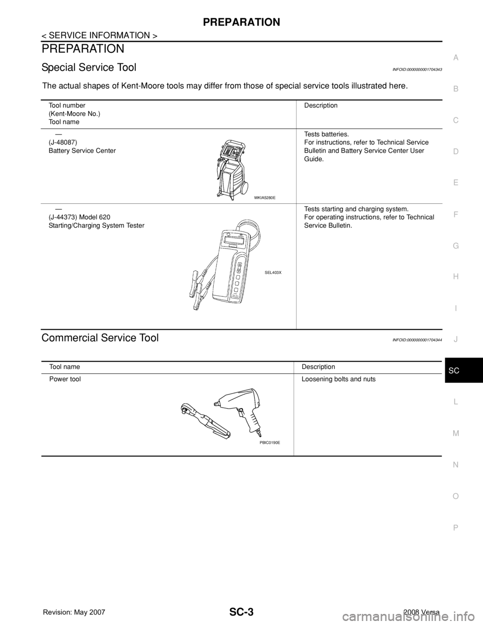
Special Service ToolINFOID:0000000001704343
The actual shapes of Kent-Moore tools may differ from those of special service tools illustrated here.
Commercial Service ToolINFOID:0000000001704344
Tool number
(Kent-Moore No.)
Tool nameDescription
—
(J-48087)
Battery Service CenterTests batteries.
For instructions, refer to Technical Service
Bulletin and Battery Service Center User
Guide.
—
(J-44373) Model 620
Starting/Charging System TesterTests starting and charging system.
For operating instructions, refer to Technical
Service Bulletin.
WKIA5280E
SEL403X
Tool nameDescription
Power toolLoosening bolts and nuts
PBIC0190E