Page 2355 of 2771
OIL
MTC-17
< SERVICE INFORMATION >
C
D
E
F
G
H
I
K
L
MA
B
MTC
N
O
P
*1: If refrigerant leak is small, no addition of oil is needed.
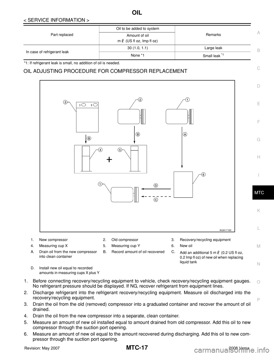
OIL ADJUSTING PROCEDURE FOR COMPRESSOR REPLACEMENT
1. Before connecting recovery/recycling equipment to vehicle, check recovery/recycling equipment gauges.
No refrigerant pressure should be displayed. If NG, recover refrigerant from equipment lines.
2. Discharge refrigerant into the refrigerant recovery/recycling equipment. Measure oil discharged into the
recovery/recycling equipment.
3. Drain the oil from the old (removed) compressor into a graduated container and recover the amount of oil
drained.
4. Drain the oil from the new compressor into a separate, clean container.
5. Measure an amount of new oil installed equal to amount drained from old compressor. Add this oil to new
compressor through the suction port opening.
6. Measure an amount of new oil equal to the amount recovered during discharging. Add this oil to new com-
pressor through the suction port opening.
In case of refrigerant leak30 (1.0, 1.1) Large leak
None *1
Small leak *1
Part replacedOil to be added to system
Remarks
Amount of oil
m (US fl oz, Imp fl oz)
1. New compressor 2. Old compressor 3. Recovery/recycling equipment
4. Measuring cup X 5. Measuring cup Y 6. New oil
A. Drain oil from the new compressor
into clean containerB. Record amount of oil recovered C.
Add an additional 5 m (0.2 US fl oz,
0.2 Imp fl oz) of new oil when replacing
liquid tank
D. Install new oil equal to recorded
amounts in measuring cups X plus Y
WJIA1716E
Page 2395 of 2771
THERMO CONTROL AMPLIFIER
MTC-57
< SERVICE INFORMATION >
C
D
E
F
G
H
I
K
L
MA
B
MTC
N
O
P
THERMO CONTROL AMPLIFIER
Removal and InstallationINFOID:0000000001704311
NOTE:
Only TYPE 1 systems are equipped with a thermo control amplifier.
REMOVAL
1. Remove evaporator. Refer to MTC-83, "Removal and Installation of Evaporator" .
CAUTION:
Cap or wrap the joint of the pipe with suitable material such as vinyl tape to avoid the entry of air.
2. Remove thermo control amp. (1) from evaporator (2).
INSTALLATION
Installation is in the reverse order of removal.
CAUTION:
• Replace O-rings for A/C piping with new ones, and apply compressor oil when installing.
• Mark the mounting position of thermo control amp.
• When recharging refrigerant, check for leaks.
ZJIA0798J
Page 2397 of 2771
A/C UNIT ASSEMBLY
MTC-59
< SERVICE INFORMATION >
C
D
E
F
G
H
I
K
L
MA
B
MTC
N
O
P
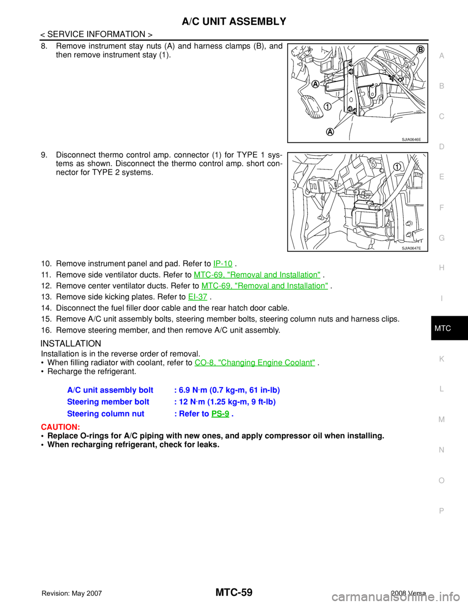
8. Remove instrument stay nuts (A) and harness clamps (B), and
then remove instrument stay (1).
9. Disconnect thermo control amp. connector (1) for TYPE 1 sys-
tems as shown. Disconnect the thermo control amp. short con-
nector for TYPE 2 systems.
10. Remove instrument panel and pad. Refer to IP-10
.
11. Remove side ventilator ducts. Refer to MTC-69, "
Removal and Installation" .
12. Remove center ventilator ducts. Refer to MTC-69, "
Removal and Installation" .
13. Remove side kicking plates. Refer to EI-37
.
14. Disconnect the fuel filler door cable and the rear hatch door cable.
15. Remove A/C unit assembly bolts, steering member bolts, steering column nuts and harness clips.
16. Remove steering member, and then remove A/C unit assembly.
INSTALLATION
Installation is in the reverse order of removal.
• When filling radiator with coolant, refer to CO-8, "
Changing Engine Coolant" .
• Recharge the refrigerant.
CAUTION:
• Replace O-rings for A/C piping with new ones, and apply compressor oil when installing.
• When recharging refrigerant, check for leaks.
SJIA0646E
SJIA0647E
A/C unit assembly bolt : 6.9 N·m (0.7 kg-m, 61 in-lb)
Steering member bolt : 12 N·m (1.25 kg-m, 9 ft-lb)
Steering column nut : Refer to PS-9
.
Page 2412 of 2771
MTC-74
< SERVICE INFORMATION >
REFRIGERANT LINES
REFRIGERANT LINES
HFC-134a (R-134a) Service ProcedureINFOID:0000000001704322
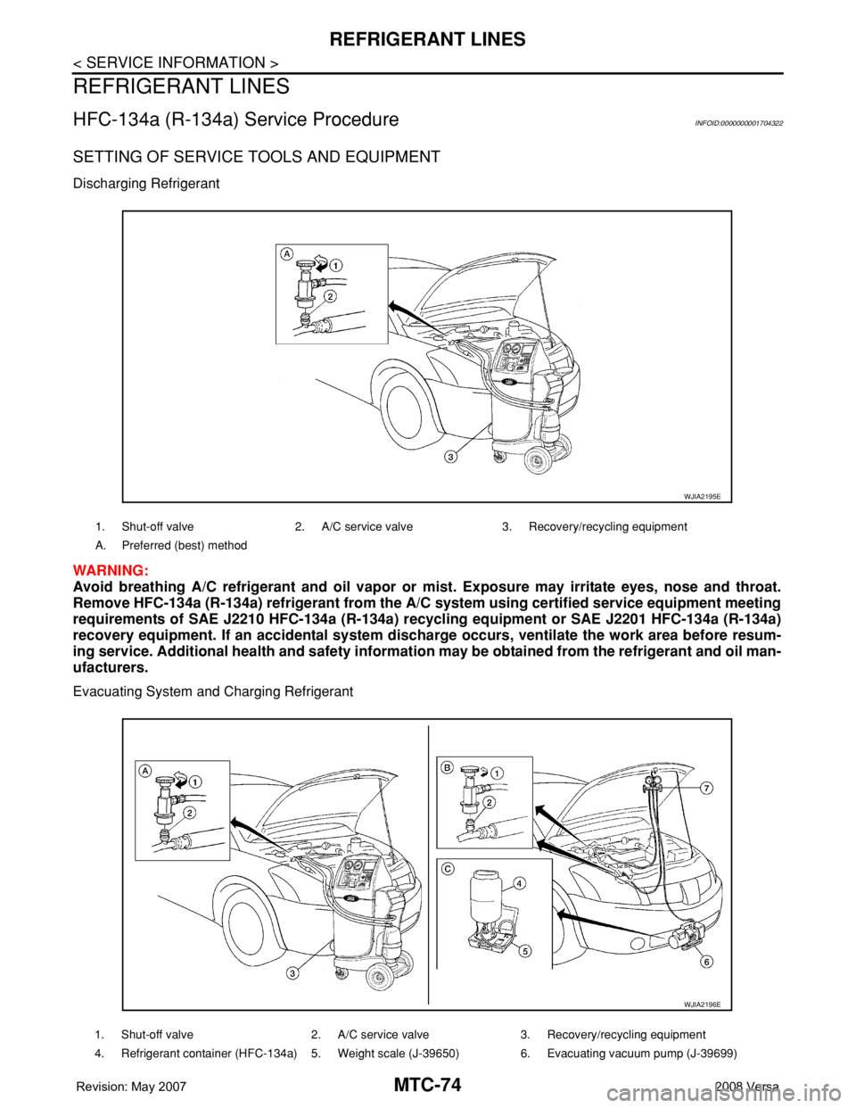
SETTING OF SERVICE TOOLS AND EQUIPMENT
Discharging Refrigerant
WARNING:
Avoid breathing A/C refrigerant and oil vapor or mist. Exposure may irritate eyes, nose and throat.
Remove HFC-134a (R-134a) refrigerant from the A/C system using certified service equipment meeting
requirements of SAE J2210 HFC-134a (R-134a) recycling equipment or SAE J2201 HFC-134a (R-134a)
recovery equipment. If an accidental system discharge occurs, ventilate the work area before resum-
ing service. Additional health and safety information may be obtained from the refrigerant and oil man-
ufacturers.
Evacuating System and Charging Refrigerant
1. Shut-off valve 2. A/C service valve 3. Recovery/recycling equipment
A. Preferred (best) method
WJIA2195E
1. Shut-off valve 2. A/C service valve 3. Recovery/recycling equipment
4. Refrigerant container (HFC-134a) 5. Weight scale (J-39650) 6. Evacuating vacuum pump (J-39699)
WJIA2196E
Page 2413 of 2771
REFRIGERANT LINES
MTC-75
< SERVICE INFORMATION >
C
D
E
F
G
H
I
K
L
MA
B
MTC
N
O
P
7. Manifold gauge set (J-39183) A. Preferred (best) method B. Alternative method
C. For charging
*1MTC-16, "
Maintenance of Oil Quanti-
ty in Compressor"
*2MTC-84, "Checking of Refrigerant
Leaks"
*3MTC-85, "Electronic Refrigerant
Leak Detector"
*4MTC-45, "Insufficient Cooling"
WJIA1923E
Page 2417 of 2771
REFRIGERANT LINES
MTC-79
< SERVICE INFORMATION >
C
D
E
F
G
H
I
K
L
MA
B
MTC
N
O
P
INSPECTION FOR CLUTCH DISC TO PULLEY CLEARANCE
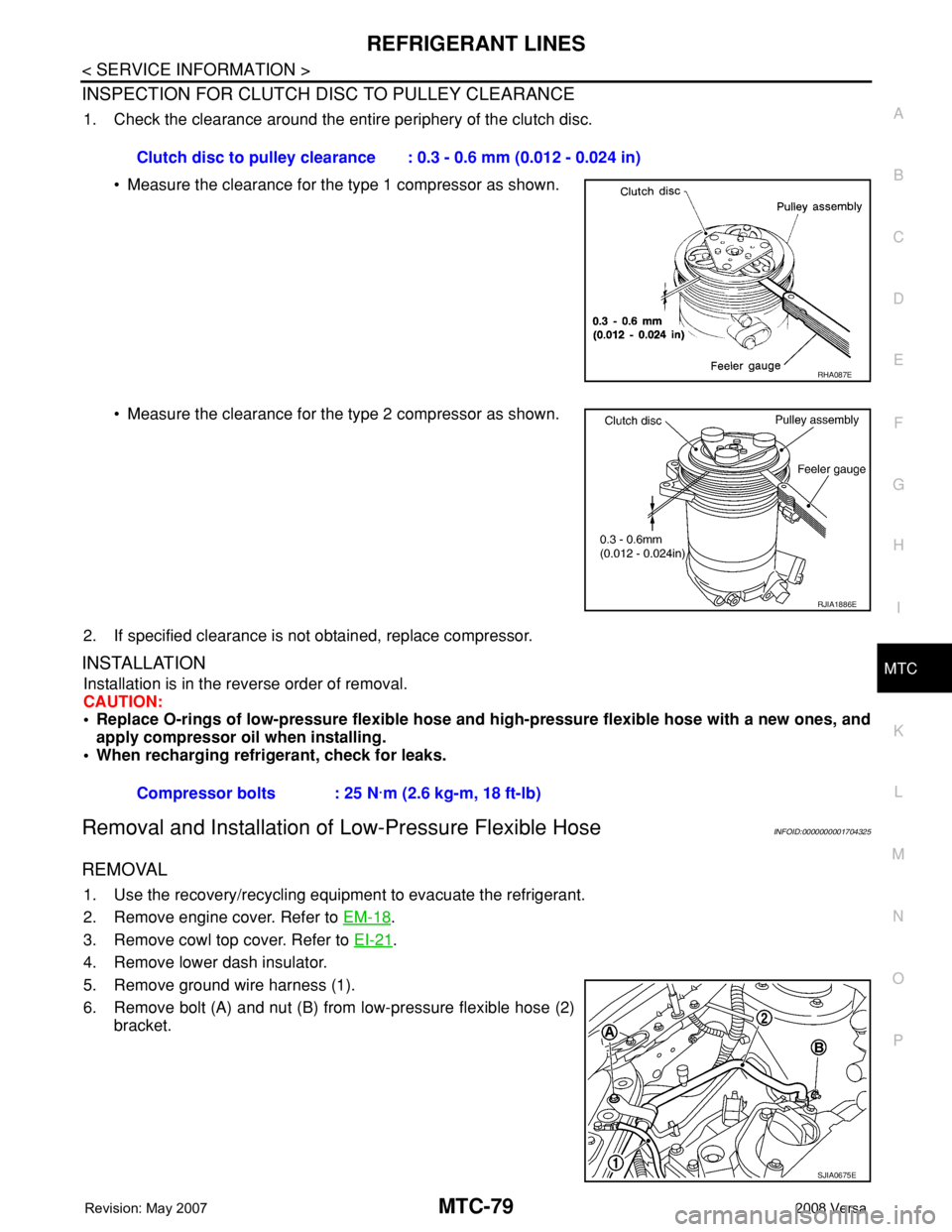
1. Check the clearance around the entire periphery of the clutch disc.
• Measure the clearance for the type 1 compressor as shown.
• Measure the clearance for the type 2 compressor as shown.
2. If specified clearance is not obtained, replace compressor.
INSTALLATION
Installation is in the reverse order of removal.
CAUTION:
• Replace O-rings of low-pressure flexible hose and high-pressure flexible hose with a new ones, and
apply compressor oil when installing.
• When recharging refrigerant, check for leaks.
Removal and Installation of Low-Pressure Flexible HoseINFOID:0000000001704325
REMOVAL
1. Use the recovery/recycling equipment to evacuate the refrigerant.
2. Remove engine cover. Refer to EM-18
.
3. Remove cowl top cover. Refer to EI-21
.
4. Remove lower dash insulator.
5. Remove ground wire harness (1).
6. Remove bolt (A) and nut (B) from low-pressure flexible hose (2)
bracket.Clutch disc to pulley clearance : 0.3 - 0.6 mm (0.012 - 0.024 in)
RHA087E
RJIA1886E
Compressor bolts : 25 N·m (2.6 kg-m, 18 ft-lb)
SJIA0675E
Page 2418 of 2771
MTC-80
< SERVICE INFORMATION >
REFRIGERANT LINES
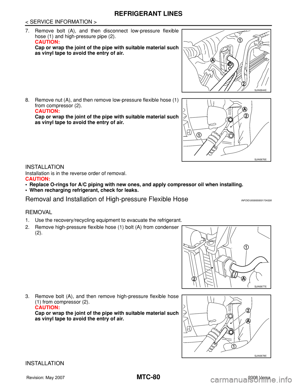
7. Remove bolt (A), and then disconnect low-pressure flexible
hose (1) and high-pressure pipe (2).
CAUTION:
Cap or wrap the joint of the pipe with suitable material such
as vinyl tape to avoid the entry of air.
8. Remove nut (A), and then remove low-pressure flexible hose (1)
from compressor (2).
CAUTION:
Cap or wrap the joint of the pipe with suitable material such
as vinyl tape to avoid the entry of air.
INSTALLATION
Installation is in the reverse order of removal.
CAUTION:
• Replace O-rings for A/C piping with new ones, and apply compressor oil when installing.
• When recharging refrigerant, check for leaks.
Removal and Installation of High-pressure Flexible HoseINFOID:0000000001704326
REMOVAL
1. Use the recovery/recycling equipment to evacuate the refrigerant.
2. Remove high-pressure flexible hose (1) bolt (A) from condenser
(2).
3. Remove bolt (A), and then remove high-pressure flexible hose
(1) from compressor (2).
CAUTION:
Cap or wrap the joint of the pipe with suitable material such
as vinyl tape to avoid the entry of air.
INSTALLATION
SJIA0644E
SJIA0676E
SJIA0677E
SJIA0678E
Page 2419 of 2771
REFRIGERANT LINES
MTC-81
< SERVICE INFORMATION >
C
D
E
F
G
H
I
K
L
MA
B
MTC
N
O
P
Installation is in the reverse order of removal.
CAUTION:
• Replace O-rings of high-pressure flexible hose with a new ones, and apply compressor oil when
installing.
• When recharging refrigerant, check for leaks.
Removal and Installation of High-pressure PipeINFOID:0000000001704327
REMOVAL
1. Remove low-pressure flexible hose. Refer to MTC-79, "Removal and Installation of Low-Pressure Flexible
Hose".
2. Remove high-pressure pipe from the clips.
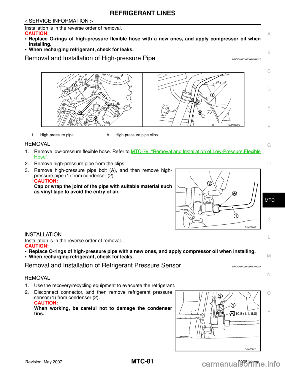
3. Remove high-pressure pipe bolt (A), and then remove high-
pressure pipe (1) from condenser (2).
CAUTION:
Cap or wrap the joint of the pipe with suitable material such
as vinyl tape to avoid the entry of air.
INSTALLATION
Installation is in the reverse order of removal.
CAUTION:
• Replace O-rings of high-pressure pipe with a new ones, and apply compressor oil when installing.
• When recharging refrigerant, check for leaks.
Removal and Installation of Refrigerant Pressure SensorINFOID:0000000001704328
REMOVAL
1. Use the recovery/recycling equipment to evacuate the refrigerant.
2. Disconnect connector, and then remove refrigerant pressure
sensor (1) from condenser (2).
CAUTION:
When working, be careful not to damage the condenser
fins.
1. High-pressure pipe A. High-pressure pipe clips
SJIA0679E
SJIA0680E
SJIA0681E