2008 NISSAN LATIO ECO mode
[x] Cancel search: ECO modePage 2004 of 2771
![NISSAN LATIO 2008 Service Repair Manual TROUBLE DIAGNOSIS
LAN-13
< FUNCTION DIAGNOSIS >[CAN FUNDAMENTAL]
C
D
E
F
G
H
I
J
L
MA
B
LAN
N
O
P
Example: CAN DIAG SUPPORT MNTR indication
Without PAST
With PAST
MONITOR ITEM (ON-BOARD DIAGNOSIS)
NOT NISSAN LATIO 2008 Service Repair Manual TROUBLE DIAGNOSIS
LAN-13
< FUNCTION DIAGNOSIS >[CAN FUNDAMENTAL]
C
D
E
F
G
H
I
J
L
MA
B
LAN
N
O
P
Example: CAN DIAG SUPPORT MNTR indication
Without PAST
With PAST
MONITOR ITEM (ON-BOARD DIAGNOSIS)
NOT](/manual-img/5/57360/w960_57360-2003.png)
TROUBLE DIAGNOSIS
LAN-13
< FUNCTION DIAGNOSIS >[CAN FUNDAMENTAL]
C
D
E
F
G
H
I
J
L
MA
B
LAN
N
O
P
Example: CAN DIAG SUPPORT MNTR indication
Without PAST
With PAST
MONITOR ITEM (ON-BOARD DIAGNOSIS)
NOTE:
For some models, CAN communication diagnosis result is received from the vehicle monitor.
JSMIA0015GB
Item PRSNT Description
Initial diagnosisOK Normal at present
NG Control unit error (Except for some control units)
Transmission diagnosisOK Normal at present
UNKWNUnable to transmit signals for 2 seconds or more.
Diagnosis not performed
Control unit name
(Reception diagnosis)OK Normal at present
UNKWNUnable to receive signals for 2 seconds or more.
Diagnosis not performed
No control unit for receiving signals. (No applicable optional parts)
Item PRSNT PAST Description
Transmission diagnosisOKOK Normal at present and in the past
1 – 39Normal at present, but unable to transmit signals for 2 seconds or more
in the past. (The number indicates the number of ignition switch cycles
from OFF to ON.)
UNKWN 0 Unable to transmit signals for 2 seconds or more at present.
Control unit name
(Reception diagnosis)OKOK Normal at present and in the past
1 – 39Normal at present, but unable to receive signals for 2 seconds or more
in the past. (The number indicates the number of ignition switch cycles
from OFF to ON.)
UNKWN 0 Unable to receive signals for 2 seconds or more at present.
––Diagnosis not performed.
No control unit for receiving signals. (No applicable optional parts)
Page 2150 of 2771
HEADLAMP (FOR USA)
LT-13
< SERVICE INFORMATION >
C
D
E
F
G
H
I
J
L
MA
B
LT
N
O
P
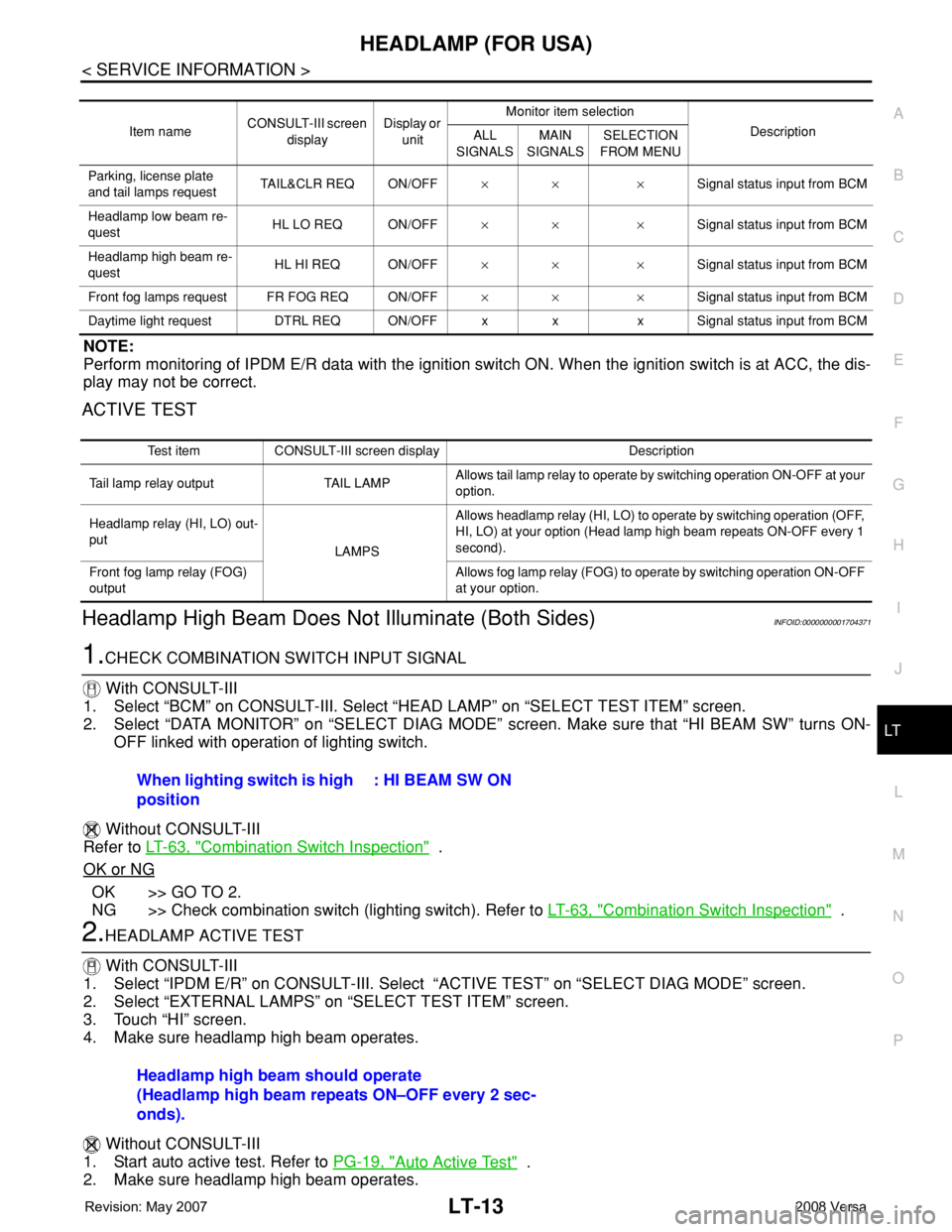
NOTE:
Perform monitoring of IPDM E/R data with the ignition switch ON. When the ignition switch is at ACC, the dis-
play may not be correct.
ACTIVE TEST
Headlamp High Beam Does Not Illuminate (Both Sides)INFOID:0000000001704371
1.CHECK COMBINATION SWITCH INPUT SIGNAL
With CONSULT-III
1. Select “BCM” on CONSULT-III. Select “HEAD LAMP” on “SELECT TEST ITEM” screen.
2. Select “DATA MONITOR” on “SELECT DIAG MODE” screen. Make sure that “HI BEAM SW” turns ON-
OFF linked with operation of lighting switch.
Without CONSULT-III
Refer to LT-63, "
Combination Switch Inspection" .
OK or NG
OK >> GO TO 2.
NG >> Check combination switch (lighting switch). Refer to LT-63, "
Combination Switch Inspection" .
2.HEADLAMP ACTIVE TEST
With CONSULT-III
1. Select “IPDM E/R” on CONSULT-III. Select “ACTIVE TEST” on “SELECT DIAG MODE” screen.
2. Select “EXTERNAL LAMPS” on “SELECT TEST ITEM” screen.
3. Touch “HI” screen.
4. Make sure headlamp high beam operates.
Without CONSULT-III
1. Start auto active test. Refer to PG-19, "
Auto Active Test" .
2. Make sure headlamp high beam operates.
Item nameCONSULT-III screen
displayDisplay or
unitMonitor item selection
Description
ALL
SIGNALSMAIN
SIGNALSSELECTION
FROM MENU
Parking, license plate
and tail lamps requestTAIL&CLR REQ ON/OFF×× ×Signal status input from BCM
Headlamp low beam re-
questHL LO REQ ON/OFF×× ×Signal status input from BCM
Headlamp high beam re-
questHL HI REQ ON/OFF×× ×Signal status input from BCM
Front fog lamps request FR FOG REQ ON/OFF×× ×Signal status input from BCM
Daytime light request DTRL REQ ON/OFF x x x Signal status input from BCM
Test item CONSULT-III screen display Description
Tail lamp relay output TAIL LAMPAllows tail lamp relay to operate by switching operation ON-OFF at your
option.
Headlamp relay (HI, LO) out-
put
LAMPSAllows headlamp relay (HI, LO) to operate by switching operation (OFF,
HI, LO) at your option (Head lamp high beam repeats ON-OFF every 1
second).
Front fog lamp relay (FOG)
outputAllows fog lamp relay (FOG) to operate by switching operation ON-OFF
at your option.
When lighting switch is high
position: HI BEAM SW ON
Headlamp high beam should operate
(Headlamp high beam repeats ON–OFF every 2 sec-
onds).
Page 2151 of 2771
LT-14
< SERVICE INFORMATION >
HEADLAMP (FOR USA)
OK or NG
OK >> GO TO 3.
NG >> GO TO 4.
3.CHECK IPDM E/R
1. Select “IPDM E/R” on CONSULT-III. Select “DATA MONITOR” on “SELECT DIAG MODE” screen.
2. Make sure “HL HI REQ” turns ON when lighting switch is in high position.
OK or NG
OK >> Replace IPDM E/R. Refer to PG-26, "Removal and Installation of IPDM E/R" .
NG >> Replace BCM. Refer to BCS-18, "
Removal and Installation of BCM" .
4.HEADLAMP HIGH BEAM FUSE INSPECTION
Inspect 10A fuse No. 34 (LH) and fuse No. 35 (RH).
OK or NG
OK >> GO TO 5.
NG >> Repair harness.
5.BULB INSPECTION
Inspect inoperative headlamp bulbs.
OK or NG
OK >> GO TO 6.
NG >> Replace headlamp bulb. LT-22, "
Bulb Replacement" .
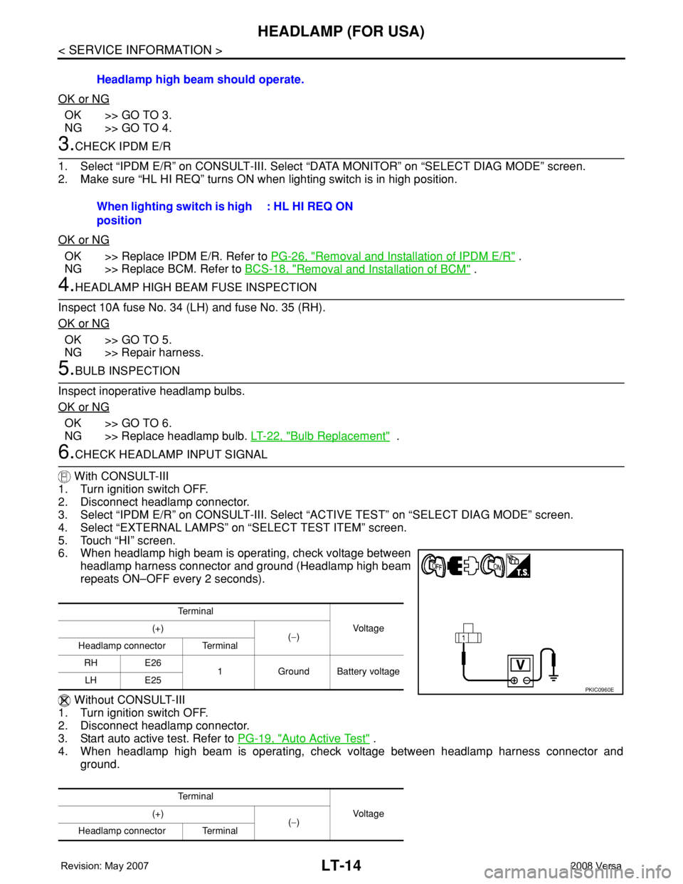
6.CHECK HEADLAMP INPUT SIGNAL
With CONSULT-III
1. Turn ignition switch OFF.
2. Disconnect headlamp connector.
3. Select “IPDM E/R” on CONSULT-III. Select “ACTIVE TEST” on “SELECT DIAG MODE” screen.
4. Select “EXTERNAL LAMPS” on “SELECT TEST ITEM” screen.
5. Touch “HI” screen.
6. When headlamp high beam is operating, check voltage between
headlamp harness connector and ground (Headlamp high beam
repeats ON–OFF every 2 seconds).
Without CONSULT-III
1. Turn ignition switch OFF.
2. Disconnect headlamp connector.
3. Start auto active test. Refer to PG-19, "
Auto Active Test" .
4. When headlamp high beam is operating, check voltage between headlamp harness connector and
ground.Headlamp high beam should operate.
When lighting switch is high
position: HL HI REQ ON
Te r m i n a l
Vo l ta g e (+)
(−)
Headlamp connector Terminal
RH E26
1 Ground Battery voltage
LH E25
Te r m i n a l
Vo l ta g e (+)
(−)
Headlamp connector Terminal
PKIC0960E
Page 2236 of 2771
INTERIOR ROOM LAMP
LT-99
< SERVICE INFORMATION >
C
D
E
F
G
H
I
J
L
MA
B
LT
N
O
P
3. Perform the preliminary check. Refer to LT-99, "Preliminary Check" .
4. Check symptom and repair or replace the cause of the malfunction.
5. Does the interior room lamp operate normally? If YES, GO TO 6. If NO, GO TO 4.
6. Inspection End
Preliminary CheckINFOID:0000000001704474
CHECK POWER SUPPLY AND GROUND CIRCUIT FOR BCM
Refer to BCS-15, "BCM Power Supply and Ground Circuit Inspection" .
CHECK POWER SUPPLY AND GROUND CIRCUIT FOR IPDM E/R
Refer to LT- 11 , "Preliminary Check" .
CONSULT-III Function (BCM)INFOID:0000000001704475
Refer to LT- 11 , "CONSULT-III Function (BCM)".
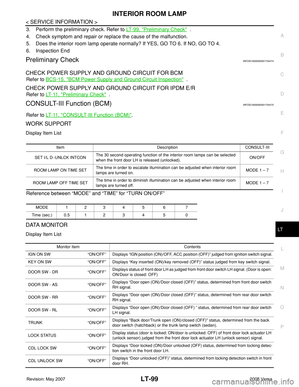
WORK SUPPORT
Display Item List
Reference between “MODE” and “TIME” for “TURN ON/OFF”
DATA MONITOR
Display Item List
Item Description CONSULT-III
SET I/L D−UNLCK INTCONThe 30 second operating function of the interior room lamps can be selected
when the front door LH is released (unlocked). ON/OFF
ROOM LAMP ON TIME SETThe time in order to escalate illumination can be adjusted when interior room
lamps are turned on.MODE 1 – 7
ROOM LAMP OFF TIME SETThe time in order to diminish illumination can be adjusted when interior room
lamps are turned off.MODE 1 – 7
MODE 123 4 5 6 7
Time (sec.) 0.5 1 2 3 4 5 0
Monitor item Contents
IGN ON SW “ON/OFF” Displays “IGN position (ON)/OFF, ACC position (OFF)” judged from ignition switch signal.
KEY ON SW “ON/OFF” Displays “Key inserted (ON)/key removed (OFF)” status judged from key switch signal.
DOOR SW - DR “ON/OFF”Displays status of front door LH as judged from front door switch LH signal. (Door is open:
ON/Door is closed: OFF)
DOOR SW - AS “ON/OFF”Displays “Door open (ON)/Door closed (OFF)” status, determined from front door switch
RH signal.
DOOR SW - RR “ON/OFF”Displays “Door open (ON)/Door closed (OFF)” status, determined from rear door switch
RH signal.
DOOR SW - RL “ON/OFF”Displays “Door open (ON)/Door closed (OFF) ” status, determined from rear door switch
LH signal.
TRUNK “ON/OFF”Displays "Back door/Trunk open (ON)/closed (OFF)" status, determined from the back
door switch (hatchback) or the trunk lamp switch (sedan).
LOCK STATUS “ON/OFF”Display status (door is locked: ON/door is unlocked: OFF) of front door lock actuator LH
(unlock sensor) judged from the front door lock actuator LH (unlock sensor) signal.
CDL LOCK SW “ON/OFF”Displays “Door locked (ON)/Door unlocked (OFF) status, determined from locking detec-
tion switch in the front door LH.
CDL UNLOCK SW “ON/OFF”Displays “Door unlocked (OFF)” status, determined from locking detection switch in front
door RH.
Page 2256 of 2771
LU-6
< SERVICE INFORMATION >
ENGINE OIL
ENGINE OIL
InspectionINFOID:0000000001702518
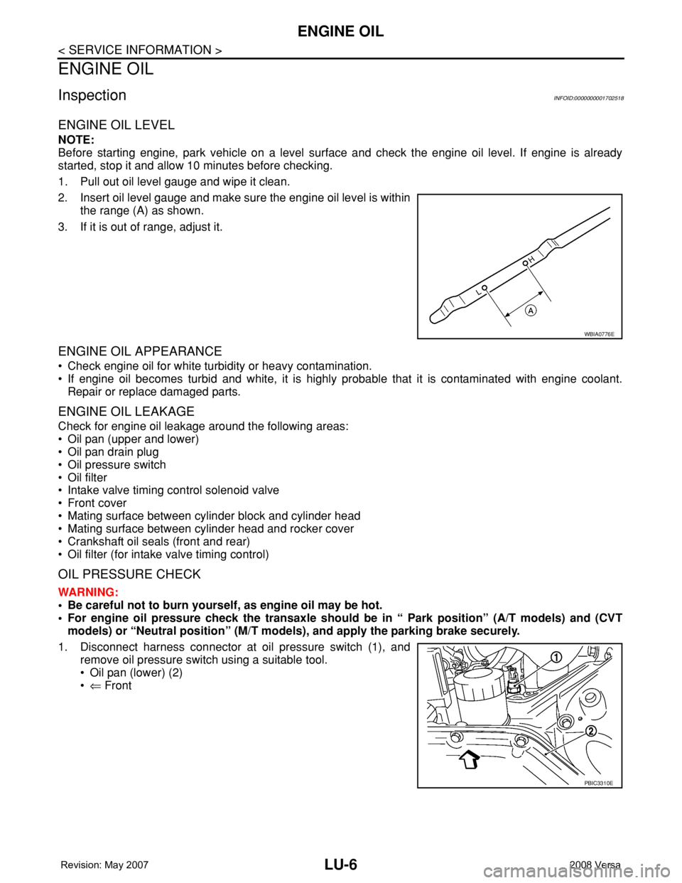
ENGINE OIL LEVEL
NOTE:
Before starting engine, park vehicle on a level surface and check the engine oil level. If engine is already
started, stop it and allow 10 minutes before checking.
1. Pull out oil level gauge and wipe it clean.
2. Insert oil level gauge and make sure the engine oil level is within
the range (A) as shown.
3. If it is out of range, adjust it.
ENGINE OIL APPEARANCE
• Check engine oil for white turbidity or heavy contamination.
• If engine oil becomes turbid and white, it is highly probable that it is contaminated with engine coolant.
Repair or replace damaged parts.
ENGINE OIL LEAKAGE
Check for engine oil leakage around the following areas:
• Oil pan (upper and lower)
• Oil pan drain plug
• Oil pressure switch
• Oil filter
• Intake valve timing control solenoid valve
• Front cover
• Mating surface between cylinder block and cylinder head
• Mating surface between cylinder head and rocker cover
• Crankshaft oil seals (front and rear)
• Oil filter (for intake valve timing control)
OIL PRESSURE CHECK
WARNING:
• Be careful not to burn yourself, as engine oil may be hot.
• For engine oil pressure check the transaxle should be in “ Park position” (A/T models) and (CVT
models) or “Neutral position” (M/T models), and apply the parking brake securely.
1. Disconnect harness connector at oil pressure switch (1), and
remove oil pressure switch using a suitable tool.
• Oil pan (lower) (2)
•⇐ Front
WBIA0776E
PBIC3310E
Page 2394 of 2771
MTC-56
< SERVICE INFORMATION >
CONTROLLER
Disassembly and Assembly
INFOID:0000000001704310
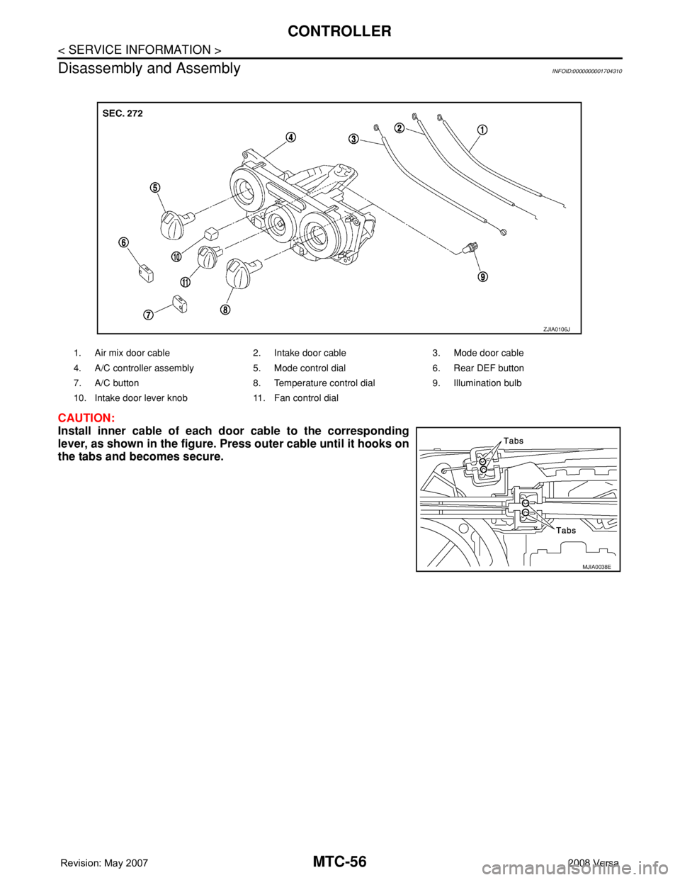
CAUTION:
Install inner cable of each door cable to the corresponding
lever, as shown in the figure. Press outer cable until it hooks on
the tabs and becomes secure.
1. Air mix door cable 2. Intake door cable 3. Mode door cable
4. A/C controller assembly 5. Mode control dial 6. Rear DEF button
7. A/C button 8. Temperature control dial 9. Illumination bulb
10. Intake door lever knob 11. Fan control dial
ZJIA0106J
MJIA0038E
Page 2425 of 2771
REFRIGERANT LINES
MTC-87
< SERVICE INFORMATION >
C
D
E
F
G
H
I
K
L
MA
B
MTC
N
O
P
Check all around the service valves. Ensure service valve caps are secured on the service valves (to
prevent leaks).
NOTE:
After removing A/C manifold gauge set from service valves, wipe any residue from valves to prevent any
false readings by leak detector.
• Cooling unit (Evaporator)
With engine OFF, turn blower fan on “High” for at least 15 seconds to dissipate any refrigerant trace in
the cooling unit. Wait a minimum of 10 minutes accumulation time (refer to the manufacturer’s recom-
mended procedure for actual wait time) before inserting the leak detector probe into the drain hose.
Keep the probe inserted for at least 10 seconds. Use caution not to contaminate the probe tip with water
or dirt that may be in the drain hose.
5. If a leak detector detects a leak, verify at least once by blowing compressed air into area of suspected
leak, then repeat check as outlined above.
6. Do not stop when one leak is found. Continue to check for additional leaks at all system components.
If no leaks are found, perform steps 7-10.
7. Start engine.
8. Set the heater A/C control as follows;
a. A/C switch: ON
b. Mode control dial position: VENT (Ventilation)
c. Intake door lever position: Recirculation
d. Max. cold temperature
e. Fan speed: High
9. Run engine at 1,500 rpm for at least 2 minutes.
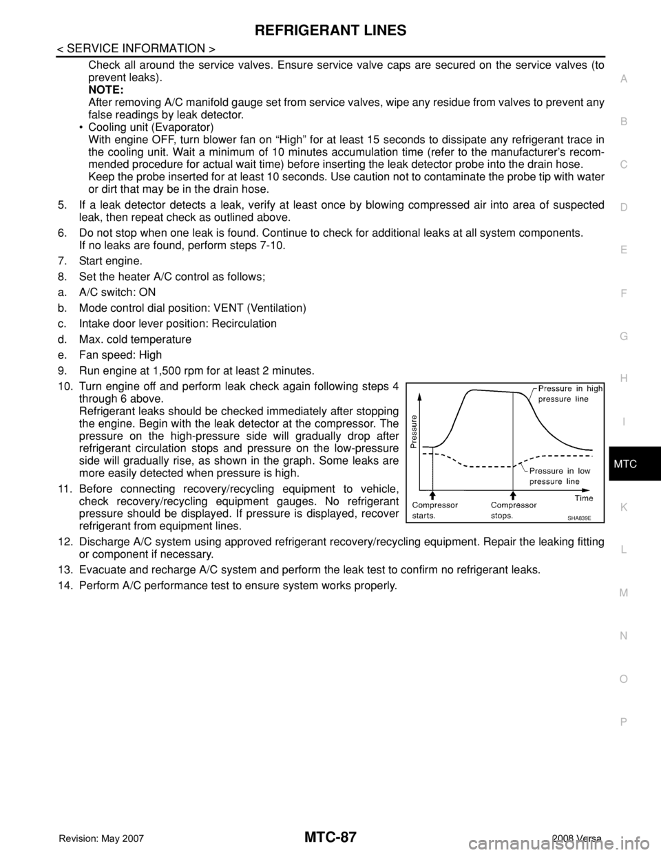
10. Turn engine off and perform leak check again following steps 4
through 6 above.
Refrigerant leaks should be checked immediately after stopping
the engine. Begin with the leak detector at the compressor. The
pressure on the high-pressure side will gradually drop after
refrigerant circulation stops and pressure on the low-pressure
side will gradually rise, as shown in the graph. Some leaks are
more easily detected when pressure is high.
11. Before connecting recovery/recycling equipment to vehicle,
check recovery/recycling equipment gauges. No refrigerant
pressure should be displayed. If pressure is displayed, recover
refrigerant from equipment lines.
12. Discharge A/C system using approved refrigerant recovery/recycling equipment. Repair the leaking fitting
or component if necessary.
13. Evacuate and recharge A/C system and perform the leak test to confirm no refrigerant leaks.
14. Perform A/C performance test to ensure system works properly.
SHA839E
Page 2450 of 2771
IPDM E/R (INTELLIGENT POWER DISTRIBUTION MODULE ENGINE ROOM)
PG-17
< SERVICE INFORMATION >
C
D
E
F
G
H
I
J
L
MA
B
PG
N
O
P
IPDM E/R STATUS CONTROL
In order to save power, IPDM E/R switches status by itself based on each operating condition.
1. CAN communication status
• CAN communication is normally performed with other control units.
• Individual unit control by IPDM E/R is normally performed.
• When sleep request signal is received from BCM, mode is switched to sleep waiting status.
2. Sleep waiting status
• Process to stop CAN communication is activated.
• All systems controlled by IPDM E/R are stopped. When 1 second has elapsed after CAN communica-
tion with other control units is stopped, mode switches to sleep status.
3. Sleep status
• IPDM E/R operates in low current-consumption mode.
• CAN communication is stopped.
• When a change in CAN communication signal is detected, mode switches to CAN communication sta-
tus.
• When a change in ignition switch signal is detected, mode switches to CAN communication status.
CAN Communication System DescriptionINFOID:0000000001704698
Refer to LAN-6, "System Description".
Function of Detecting Ignition Relay MalfunctionINFOID:0000000001704699
• When the integrated ignition relay is stuck in a "closed contact" position and cannot be turned OFF, IPDM E/
R turns ON tail and parking lamps for 10 minutes to indicate IPDM E/R malfunction.
• When the state of the integrated ignition relay does not agree with the state of the ignition switch signal
received via CAN communication, the IPDM E/R activates the tail lamp relay.
NOTE:
When the ignition switch is turned ON, the tail lamps are OFF.
CONSULT-III Function (IPDM E/R)INFOID:0000000001704700
CONSULT-III can display each diagnostic item using the diagnostic test modes shown following.
SELF-DIAGNOSTIC RESULTS
Display Item List
Rear window defogger Rear window defogger relay OFF
A/C compressor A/C relay is OFF
Front fog lamps Front fog lamp relay OFFControlled system Fail-safe mode
Ignition switch signal Ignition relay status Tail lamp relay
ON ON —
OFF OFF —
ON OFF —
OFF ON ON (10 minutes)
IPDM E/R diagnostic Mode Description
SELF-DIAG RESULTS Displays IPDM E/R self-diagnosis results.
DATA MONITOR Displays IPDM E/R input/output data in real time.
CAN DIAG SUPPORT MNTR The result of transmit/receive diagnosis of CAN communication can be read.
ACTIVE TEST Operation of electrical loads can be checked by sending drive signal to them.