2008 NISSAN LATIO ECO mode
[x] Cancel search: ECO modePage 1580 of 2771
EC-506
< SERVICE INFORMATION >
DTC P2A00 A/F SENSOR 1
• Before installing new air fuel ratio (A/F) sensor, clean exhaust system threads using Heated Oxygen
Sensor Thread Cleaner tool J-43897-18 or J-43897-12 and approved anti-seize lubricant.
>> GO TO 12.
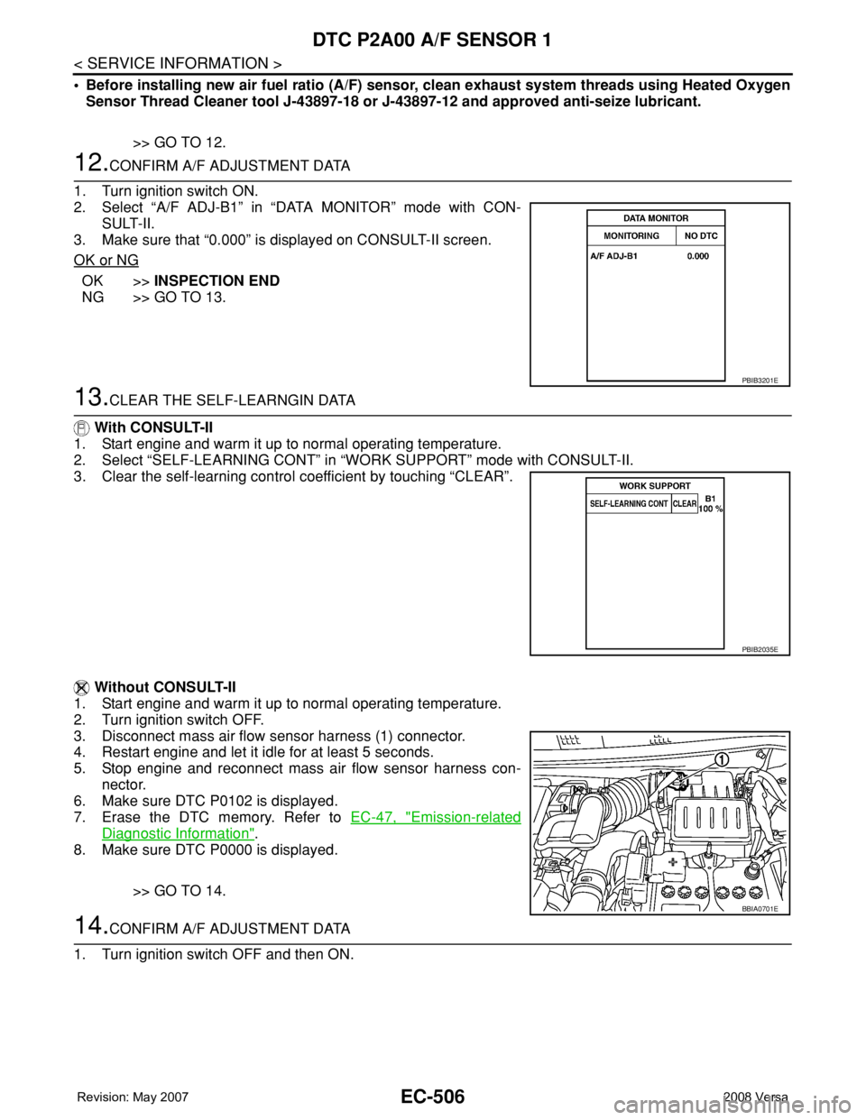
12.CONFIRM A/F ADJUSTMENT DATA
1. Turn ignition switch ON.
2. Select “A/F ADJ-B1” in “DATA MONITOR” mode with CON-
SULT-II.
3. Make sure that “0.000” is displayed on CONSULT-II screen.
OK or NG
OK >>INSPECTION END
NG >> GO TO 13.
13.CLEAR THE SELF-LEARNGIN DATA
With CONSULT-II
1. Start engine and warm it up to normal operating temperature.
2. Select “SELF-LEARNING CONT” in “WORK SUPPORT” mode with CONSULT-II.
3. Clear the self-learning control coefficient by touching “CLEAR”.
Without CONSULT-II
1. Start engine and warm it up to normal operating temperature.
2. Turn ignition switch OFF.
3. Disconnect mass air flow sensor harness (1) connector.
4. Restart engine and let it idle for at least 5 seconds.
5. Stop engine and reconnect mass air flow sensor harness con-
nector.
6. Make sure DTC P0102 is displayed.
7. Erase the DTC memory. Refer to EC-47, "
Emission-related
Diagnostic Information".
8. Make sure DTC P0000 is displayed.
>> GO TO 14.
14.CONFIRM A/F ADJUSTMENT DATA
1. Turn ignition switch OFF and then ON.
PBIB3201E
PBIB2035E
BBIA0701E
Page 1600 of 2771
EC-526
< SERVICE INFORMATION >
FUEL PUMP
FUEL PUMP
DescriptionINFOID:0000000001703065
SYSTEM DESCRIPTION
*: ECM determines the start signal status by the signals of engine speed and battery voltage.
The ECM activates the fuel pump for several seconds after the ignition switch is turned ON to improve engine
startability. If the ECM receives a engine speed signal from the crankshaft position sensor (POS) and cam-
shaft position sensor (PHASE), it knows that the engine is rotating, and causes the pump to operate. If the
engine speed signal is not received when the ignition switch is ON, the engine stalls. The ECM stops pump
operation and prevents battery discharging, thereby improving safety. The ECM does not directly drive the fuel
pump. It controls the ON/OFF fuel pump relay, which in turn controls the fuel pump.
COMPONENT DESCRIPTION
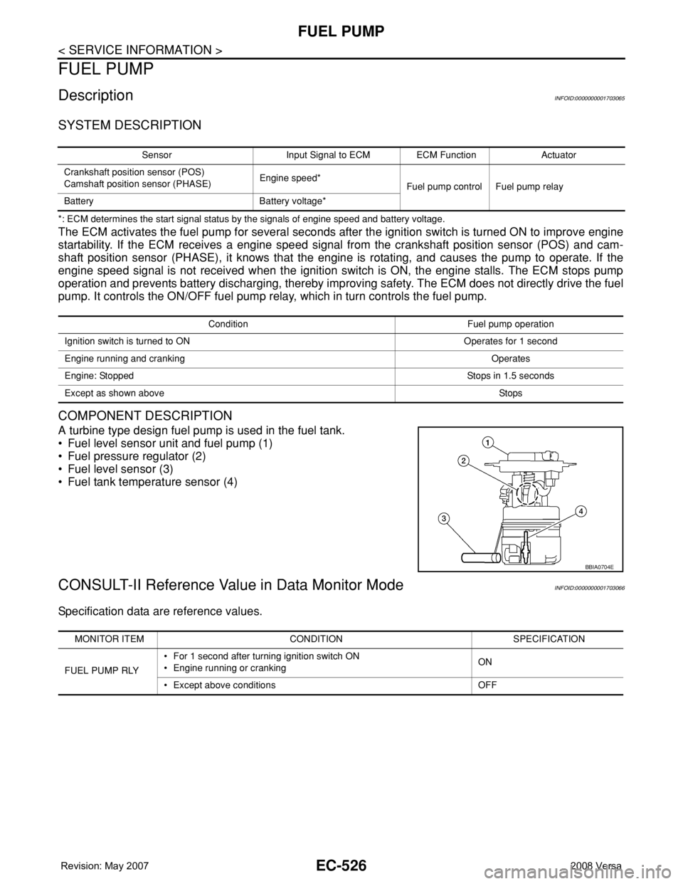
A turbine type design fuel pump is used in the fuel tank.
• Fuel level sensor unit and fuel pump (1)
• Fuel pressure regulator (2)
• Fuel level sensor (3)
• Fuel tank temperature sensor (4)
CONSULT-II Reference Value in Data Monitor ModeINFOID:0000000001703066
Specification data are reference values.
Sensor Input Signal to ECM ECM Function Actuator
Crankshaft position sensor (POS)
Camshaft position sensor (PHASE)Engine speed*
Fuel pump control Fuel pump relay
Battery Battery voltage*
Condition Fuel pump operation
Ignition switch is turned to ON Operates for 1 second
Engine running and crankingOperates
Engine: StoppedStops in 1.5 seconds
Except as shown aboveSt ops
BBIA0704E
MONITOR ITEM CONDITION SPECIFICATION
FUEL PUMP RLY• For 1 second after turning ignition switch ON
• Engine running or crankingON
• Except above conditions OFF
Page 1680 of 2771
PRECAUTIONS
EM-3
< SERVICE INFORMATION >
C
D
E
F
G
H
I
J
K
L
MA
EM
N
P O
SERVICE INFORMATION
PRECAUTIONS
Precaution for Supplemental Restraint System (SRS) "AIR BAG" and "SEAT BELT
PRE-TENSIONER"
INFOID:0000000001702460
The Supplemental Restraint System such as “AIR BAG” and “SEAT BELT PRE-TENSIONER”, used along
with a front seat belt, helps to reduce the risk or severity of injury to the driver and front passenger for certain
types of collision. This system includes seat belt switch inputs and dual stage front air bag modules. The SRS
system uses the seat belt switches to determine the front air bag deployment, and may only deploy one front
air bag, depending on the severity of a collision and whether the front occupants are belted or unbelted.
Information necessary to service the system safely is included in the SRS and SB section of this Service Man-
ual.
WARNING:
• To avoid rendering the SRS inoperative, which could increase the risk of personal injury or death in
the event of a collision which would result in air bag inflation, all maintenance must be performed by
an authorized NISSAN/INFINITI dealer.
• Improper maintenance, including incorrect removal and installation of the SRS, can lead to personal
injury caused by unintentional activation of the system. For removal of Spiral Cable and Air Bag
Module, see the SRS section.
• Do not use electrical test equipment on any circuit related to the SRS unless instructed to in this
Service Manual. SRS wiring harnesses can be identified by yellow and/or orange harnesses or har-
ness connectors.
Precaution for Procedure without Cowl Top CoverINFOID:0000000001702461
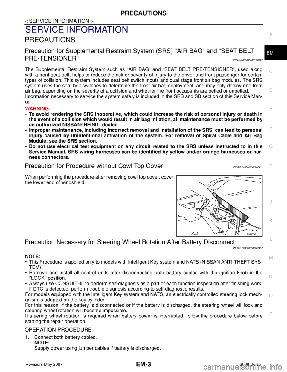
When performing the procedure after removing cowl top cover, cover
the lower end of windshield.
Precaution Necessary for Steering Wheel Rotation After Battery Disconnect
INFOID:0000000001702462
NOTE:
• This Procedure is applied only to models with Intelligent Key system and NATS (NISSAN ANTI-THEFT SYS-
TEM).
• Remove and install all control units after disconnecting both battery cables with the ignition knob in the
″LOCK″ position.
• Always use CONSULT-III to perform self-diagnosis as a part of each function inspection after finishing work.
If DTC is detected, perform trouble diagnosis according to self-diagnostic results.
For models equipped with the Intelligent Key system and NATS, an electrically controlled steering lock mech-
anism is adopted on the key cylinder.
For this reason, if the battery is disconnected or if the battery is discharged, the steering wheel will lock and
steering wheel rotation will become impossible.
If steering wheel rotation is required when battery power is interrupted, follow the procedure below before
starting the repair operation.
OPERATION PROCEDURE
1. Connect both battery cables.
NOTE:
Supply power using jumper cables if battery is discharged.
PIIB3706J
Page 1737 of 2771
EM-60
< SERVICE INFORMATION >
OIL SEAL
• Drive belt; Refer to EM-13, "Component".
• Crankshaft pulley; Refer to EM-37, "
Component".
2. Remove front oil seal using a suitable tool.
CAUTION:
Be careful not to damage front cover and crankshaft.
INSTALLATION
1. Apply new engine oil to new front oil seal joint surface and seal lip.
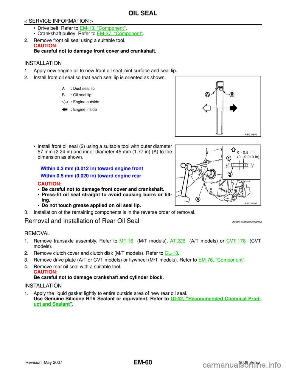
2. Install front oil seal so that each seal lip is oriented as shown.
• Install front oil seal (2) using a suitable tool with outer diameter
57 mm (2.24 in) and inner diameter 45 mm (1.77 in) (A) to the
dimension as shown.
CAUTION:
• Be careful not to damage front cover and crankshaft.
• Press-fit oil seal straight to avoid causing burrs or tilt-
ing.
• Do not touch grease applied on oil seal lip.
3. Installation of the remaining components is in the reverse order of removal.
Removal and Installation of Rear Oil SealINFOID:0000000001702500
REMOVAL
1. Remove transaxle assembly. Refer to MT-16 (M/T models), AT-226 (A/T models) or CVT-178 (CVT
models).
2. Remove clutch cover and clutch disk (M/T models). Refer to CL-13
.
3. Remove drive plate (A/T or CVT models) or flywheel (M/T models). Refer to EM-76, "
Component".
4. Remove rear oil seal with a suitable tool.
CAUTION:
Be careful not to damage crankshaft and cylinder block.
INSTALLATION
1. Apply the liquid gasket lightly to entire outside area of new rear oil seal.
Use Genuine Silicone RTV Sealant or equivalent. Refer to GI-42, "
Recommended Chemical Prod-
uct and Sealant".
A : Dust seal lip
B : Oil seal lip
: Engine outside
: Engine inside
PBIC3485J
Within 0.3 mm (0.012 in) toward engine front
Within 0.5 mm (0.020 in) toward engine rear
PBIC3729E
Page 1754 of 2771
CYLINDER BLOCK
EM-77
< SERVICE INFORMATION >
C
D
E
F
G
H
I
J
K
L
MA
EM
N
P O
Disassembly and AssemblyINFOID:0000000001702510
DISASSEMBLY
1. Remove engine and transaxle assembly from vehicle, separate transaxle from engine. Refer to EM-72.
2. Install engine to engine stand as follows;
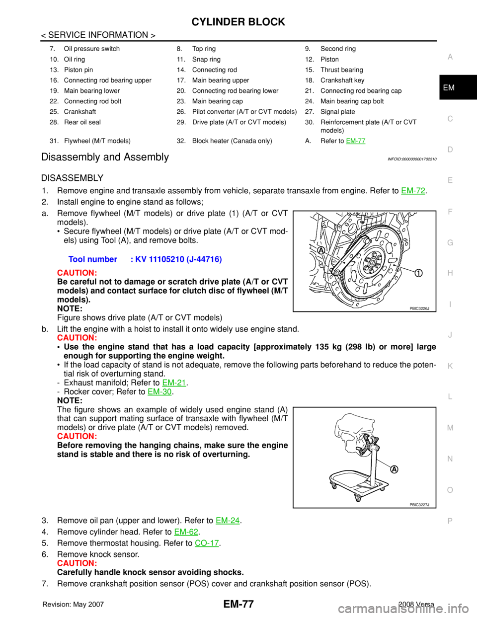
a. Remove flywheel (M/T models) or drive plate (1) (A/T or CVT
models).
• Secure flywheel (M/T models) or drive plate (A/T or CVT mod-
els) using Tool (A), and remove bolts.
CAUTION:
Be careful not to damage or scratch drive plate (A/T or CVT
models) and contact surface for clutch disc of flywheel (M/T
models).
NOTE:
Figure shows drive plate (A/T or CVT models)
b. Lift the engine with a hoist to install it onto widely use engine stand.
CAUTION:
• Use the engine stand that has a load capacity [approximately 135 kg (298 lb) or more] large
enough for supporting the engine weight.
• If the load capacity of stand is not adequate, remove the following parts beforehand to reduce the poten-
tial risk of overturning stand.
- Exhaust manifold; Refer to EM-21
.
- Rocker cover; Refer to EM-30
.
NOTE:
The figure shows an example of widely used engine stand (A)
that can support mating surface of transaxle with flywheel (M/T
models) or drive plate (A/T or CVT models) removed.
CAUTION:
Before removing the hanging chains, make sure the engine
stand is stable and there is no risk of overturning.
3. Remove oil pan (upper and lower). Refer to EM-24
.
4. Remove cylinder head. Refer to EM-62
.
5. Remove thermostat housing. Refer to CO-17
.
6. Remove knock sensor.
CAUTION:
Carefully handle knock sensor avoiding shocks.
7. Remove crankshaft position sensor (POS) cover and crankshaft position sensor (POS).
7. Oil pressure switch 8. Top ring 9. Second ring
10. Oil ring 11. Snap ring 12. Piston
13. Piston pin 14. Connecting rod 15. Thrust bearing
16. Connecting rod bearing upper 17. Main bearing upper 18. Crankshaft key
19. Main bearing lower 20. Connecting rod bearing lower 21. Connecting rod bearing cap
22. Connecting rod bolt 23. Main bearing cap 24. Main bearing cap bolt
25. Crankshaft 26. Pilot converter (A/T or CVT models) 27. Signal plate
28. Rear oil seal 29. Drive plate (A/T or CVT models) 30. Reinforcement plate (A/T or CVT
models)
31. Flywheel (M/T models) 32. Block heater (Canada only) A. Refer to EM-77
Tool number : KV 11105210 (J-44716)
PBIC3226J
PBIC3227J
Page 1779 of 2771
EM-102
< SERVICE INFORMATION >
CYLINDER BLOCK
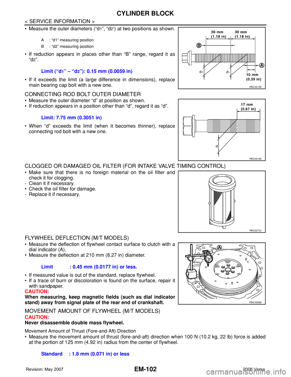
• Measure the outer diameters (“d1”, “d2”) at two positions as shown.
• If reduction appears in places other than “B” range, regard it as
“d
2”.
• If it exceeds the limit (a large difference in dimensions), replace
main bearing cap bolt with a new one.
CONNECTING ROD BOLT OUTER DIAMETER
• Measure the outer diameter “d” at position as shown.
• If reduction appears in a position other than “d”, regard it as “d”.
• When “d” exceeds the limit (when it becomes thinner), replace
connecting rod bolt with a new one.
CLOGGED OR DAMAGED OIL FILTER (FOR INTAKE VALVE TIMING CONTROL)
• Make sure that there is no foreign material on the oil filter and
check it for clogging.
- Clean it if necessary.
• Check the oil filter for damage.
- Replace it if necessary.
FLYWHEEL DEFLECTION (M/T MODELS)
• Measure the deflection of flywheel contact surface to clutch with a
dial indicator (A).
• Measure the deflection at 210 mm (8.27 in) diameter.
• If measured value is out of the standard, replace flywheel.
• If a trace of burn or discoloration is found on the surface, repair it
with sandpaper.
CAUTION:
When measuring, keep magnetic fields (such as dial indicator
stand) away from signal plate of the rear end of crankshaft.
MOVEMENT AMOUNT OF FLYWHEEL (M/T MODELS)
CAUTION:
Never disassemble double mass flywheel.
Movement Amount of Thrust (Fore-and-Aft) Direction
• Measure the movement amount of thrust (fore-and-aft) direction when 100 N (10.2 kg, 22 lb) force is added
at the portion of 125 mm (4.92 in) radius from the center of flywheel.
A : “d1” measuring position
B : “d2” measuring position
Limit (“d1” – “d2”): 0.15 mm (0.0059 in)
PBIC4015E
Limit: 7.75 mm (0.3051 in)
PBIC4016E
PBIC3273J
Limit : 0.45 mm (0.0177 in) or less.
PBIC4006E
Standard : 1.8 mm (0.071 in) or less
Page 1810 of 2771
FAX-14
< SERVICE INFORMATION >
FRONT DRIVE SHAFT
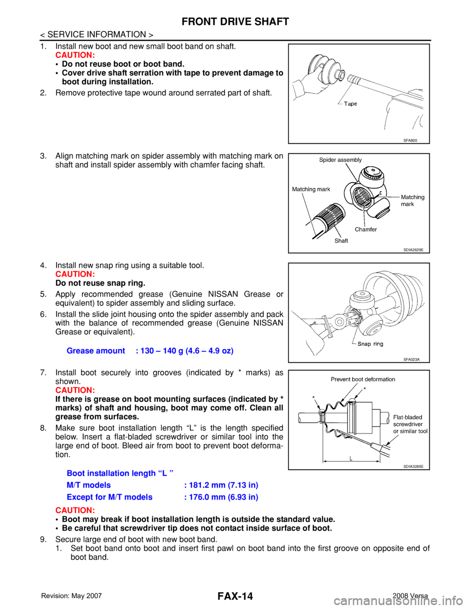
1. Install new boot and new small boot band on shaft.
CAUTION:
• Do not reuse boot or boot band.
• Cover drive shaft serration with tape to prevent damage to
boot during installation.
2. Remove protective tape wound around serrated part of shaft.
3. Align matching mark on spider assembly with matching mark on
shaft and install spider assembly with chamfer facing shaft.
4. Install new snap ring using a suitable tool.
CAUTION:
Do not reuse snap ring.
5. Apply recommended grease (Genuine NISSAN Grease or
equivalent) to spider assembly and sliding surface.
6. Install the slide joint housing onto the spider assembly and pack
with the balance of recommended grease (Genuine NISSAN
Grease or equivalent).
7. Install boot securely into grooves (indicated by * marks) as
shown.
CAUTION:
If there is grease on boot mounting surfaces (indicated by *
marks) of shaft and housing, boot may come off. Clean all
grease from surfaces.
8. Make sure boot installation length “L” is the length specified
below. Insert a flat-bladed screwdriver or similar tool into the
large end of boot. Bleed air from boot to prevent boot deforma-
tion.
CAUTION:
• Boot may break if boot installation length is outside the standard value.
• Be careful that screwdriver tip does not contact inside surface of boot.
9. Secure large end of boot with new boot band.
1. Set boot band onto boot and insert first pawl on boot band into the first groove on opposite end of
boot band.
SFA800
SDIA2629E
Grease amount : 130 – 140 g (4.6 – 4.9 oz) SFA023A
Boot installation length “L ”
M/T models : 181.2 mm (7.13 in)
Except for M/T models : 176.0 mm (6.93 in)
SDIA3285E
Page 1816 of 2771
FAX-20
< SERVICE INFORMATION >
FRONT DRIVE SHAFT
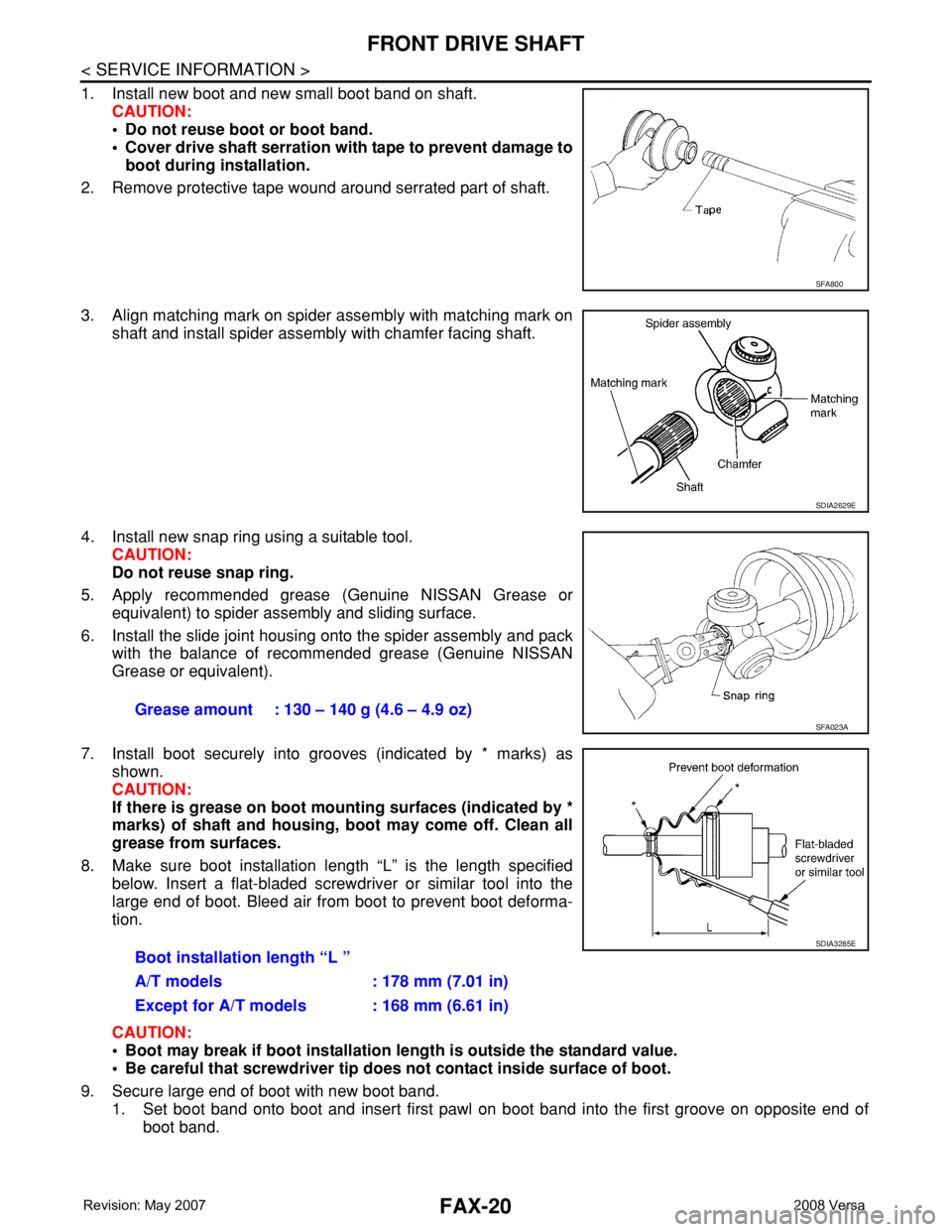
1. Install new boot and new small boot band on shaft.
CAUTION:
• Do not reuse boot or boot band.
• Cover drive shaft serration with tape to prevent damage to
boot during installation.
2. Remove protective tape wound around serrated part of shaft.
3. Align matching mark on spider assembly with matching mark on
shaft and install spider assembly with chamfer facing shaft.
4. Install new snap ring using a suitable tool.
CAUTION:
Do not reuse snap ring.
5. Apply recommended grease (Genuine NISSAN Grease or
equivalent) to spider assembly and sliding surface.
6. Install the slide joint housing onto the spider assembly and pack
with the balance of recommended grease (Genuine NISSAN
Grease or equivalent).
7. Install boot securely into grooves (indicated by * marks) as
shown.
CAUTION:
If there is grease on boot mounting surfaces (indicated by *
marks) of shaft and housing, boot may come off. Clean all
grease from surfaces.
8. Make sure boot installation length “L” is the length specified
below. Insert a flat-bladed screwdriver or similar tool into the
large end of boot. Bleed air from boot to prevent boot deforma-
tion.
CAUTION:
• Boot may break if boot installation length is outside the standard value.
• Be careful that screwdriver tip does not contact inside surface of boot.
9. Secure large end of boot with new boot band.
1. Set boot band onto boot and insert first pawl on boot band into the first groove on opposite end of
boot band.
SFA800
SDIA2629E
Grease amount : 130 – 140 g (4.6 – 4.9 oz) SFA023A
Boot installation length “L ”
A/T models : 178 mm (7.01 in)
Except for A/T models : 168 mm (6.61 in)
SDIA3285E