2008 NISSAN LATIO ECO mode
[x] Cancel search: ECO modePage 2452 of 2771
IPDM E/R (INTELLIGENT POWER DISTRIBUTION MODULE ENGINE ROOM)
PG-19
< SERVICE INFORMATION >
C
D
E
F
G
H
I
J
L
MA
B
PG
N
O
P
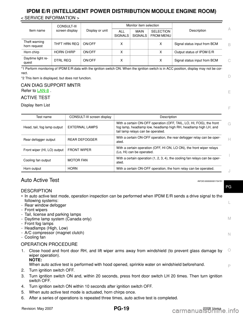
*1 Perform monitoring of IPDM E/R data with the ignition switch ON. When the ignition switch is in ACC position, display may not be cor-
rect.
*2 This item is displayed, but does not function.
CAN DIAG SUPPORT MNTR
Refer to LAN-8 .
ACTIVE TEST
Display Item List
Auto Active TestINFOID:0000000001704701
DESCRIPTION
• In auto active test mode, operation inspection can be performed when IPDM E/R sends a drive signal to the
following systems:
- Rear window defogger
- Front wipers
- Tail, license and parking lamps
- Daytime lamp system (Canada only)
- Front fog lamps
- Headlamps (High, Low)
- A/C compressor (magnet clutch)
- Cooling fan
OPERATION PROCEDURE
1. Close hood and front door RH, and lift wiper arms away from windshield (to prevent glass damage by
wiper operation).
NOTE:
When auto active test is performed with hood opened, sprinkle water on windshield beforehand.
2. Turn ignition switch OFF.
3. Turn ignition switch ON and, within 20 seconds, press front door switch LH 20 times. Then turn ignition
switch OFF.
4. Turn ignition switch ON within 10 seconds after ignition switch OFF.
5. When auto active test mode is actuated, horn chirps once.
6. After a series of operations is repeated three times, auto active test is completed.
Theft warning
horn requestTHFT HRN REQ ON/OFF X X Signal status input from BCM
Horn chirp HORN CHIRP ON/OFF X X Output status of IPDM E/R
Daytime light re-
questDTRL REQ ON/OFF X X Signal status input from BCM Item nameCONSULT-III
screen display Display or unitMonitor item selection
Description
ALL
SIGNALSMAIN
SIGNALSSELECTION
FROM MENU
Test name CONSULT-III screen display Description
Head, tail, fog lamp output EXTERNAL LAMPSWith a certain ON-OFF operation (OFF, TAIL, LO, HI, FOG), the front
fog lamp, headlamp low, headlamp high RH, headlamp high LH, and
tail lamp relays can be operated.
Rear defogger output REAR DEFOGGERWith a certain ON-OFF operation, the rear defogger relay can be oper-
ated.
Front wiper (HI, LO) output FRONT WIPERWith a certain operation (OFF, HI ON, LO ON), the front wiper relays
(Lo, Hi) can be operated.
Cooling fan output MOTOR FANWith a certain operation (1, 2, 3, 4), the cooling fan relays can be oper-
ated.
Horn output HORN With a certain ON-OFF operation, the horn relay can be operated.
Page 2453 of 2771
PG-20
< SERVICE INFORMATION >
IPDM E/R (INTELLIGENT POWER DISTRIBUTION MODULE ENGINE ROOM)
NOTE:
When auto active test mode has to be cancelled halfway, turn ignition switch OFF.
CAUTION:
Be sure to perform BL-37, "
Door Switch Check (Hatchback)" when the auto active test cannot be
performed.
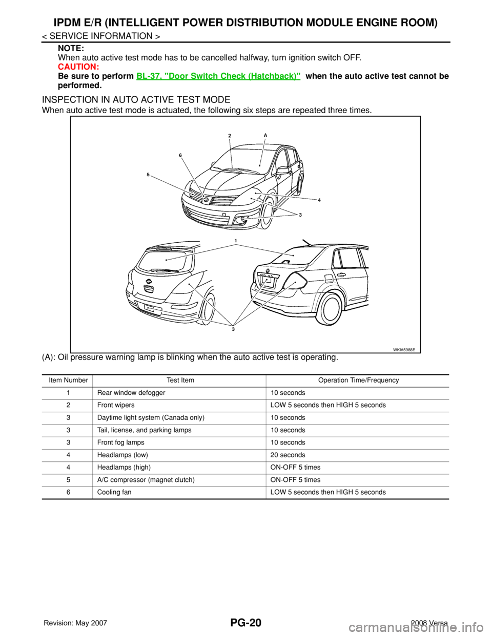
INSPECTION IN AUTO ACTIVE TEST MODE
When auto active test mode is actuated, the following six steps are repeated three times.
(A): Oil pressure warning lamp is blinking when the auto active test is operating.
WKIA5988E
Item Number Test Item Operation Time/Frequency
1 Rear window defogger 10 seconds
2 Front wipers LOW 5 seconds then HIGH 5 seconds
3 Daytime light system (Canada only) 10 seconds
3 Tail, license, and parking lamps 10 seconds
3 Front fog lamps 10 seconds
4 Headlamps (low) 20 seconds
4 Headlamps (high) ON-OFF 5 times
5 A/C compressor (magnet clutch) ON-OFF 5 times
6 Cooling fan LOW 5 seconds then HIGH 5 seconds
Page 2508 of 2771

PS-2
< SERVICE INFORMATION >
PRECAUTIONS
SERVICE INFORMATION
PRECAUTIONS
Precaution for Supplemental Restraint System (SRS) "AIR BAG" and "SEAT BELT
PRE-TENSIONER"
INFOID:0000000001703853
The Supplemental Restraint System such as “AIR BAG” and “SEAT BELT PRE-TENSIONER”, used along
with a front seat belt, helps to reduce the risk or severity of injury to the driver and front passenger for certain
types of collision. This system includes seat belt switch inputs and dual stage front air bag modules. The SRS
system uses the seat belt switches to determine the front air bag deployment, and may only deploy one front
air bag, depending on the severity of a collision and whether the front occupants are belted or unbelted.
Information necessary to service the system safely is included in the SRS and SB section of this Service Man-
ual.
WARNING:
• To avoid rendering the SRS inoperative, which could increase the risk of personal injury or death in
the event of a collision which would result in air bag inflation, all maintenance must be performed by
an authorized NISSAN/INFINITI dealer.
• Improper maintenance, including incorrect removal and installation of the SRS, can lead to personal
injury caused by unintentional activation of the system. For removal of Spiral Cable and Air Bag
Module, see the SRS section.
• Do not use electrical test equipment on any circuit related to the SRS unless instructed to in this
Service Manual. SRS wiring harnesses can be identified by yellow and/or orange harnesses or har-
ness connectors.
Precaution Necessary for Steering Wheel Rotation After Battery Disconnect
INFOID:0000000001703854
NOTE:
• This procedure is applied only to models with Intelligent Key system and NATS (NISSAN ANTI-THEFT SYS-
TEM).
• Remove and install all control units after disconnecting both battery cables with the ignition switch in the
″LOCK″ position.
• Always use CONSULT-II to perform self-diagnosis as a part of each function inspection after finishing work.
If DTC is detected, perform trouble diagnosis according to self-diagnostic results.
For models equipped with the Intelligent Key system and NATS, an electrically controlled steering lock mech-
anism is adopted on the key cylinder.
For this reason, if the battery is disconnected or if the battery is discharged, the steering wheel will lock and
steering wheel rotation will become impossible.
If steering wheel rotation is required when battery power is interrupted, follow the procedure below before
starting the repair operation.
OPERATION PROCEDURE
1. Connect both battery cables.
NOTE:
Supply power using jumper cables if battery is discharged.
2. Use the Intelligent Key or mechanical key to turn the ignition switch to the ″ACC″ position. At this time, the
steering lock will be released.
3. Disconnect both battery cables. The steering lock will remain released and the steering wheel can be
rotated.
4. Perform the necessary repair operation.
5. When the repair work is completed, return the ignition switch to the ″LOCK″ position before connecting
the battery cables. (At this time, the steering lock mechanism will engage.)
6. Perform a self-diagnosis check of all control units using CONSULT-II.
Precaution for Steering SystemINFOID:0000000001703855
• In case of removing steering gear assembly, make the final tightening with grounded and unloaded vehicle
condition, and then check wheel alignment.
• Observe the following precautions when disassembling.
Page 2545 of 2771
TROUBLE DIAGNOSIS
RF-15
< FUNCTION DIAGNOSIS >
C
D
E
F
G
H
J
K
L
MA
B
RF
N
O
P
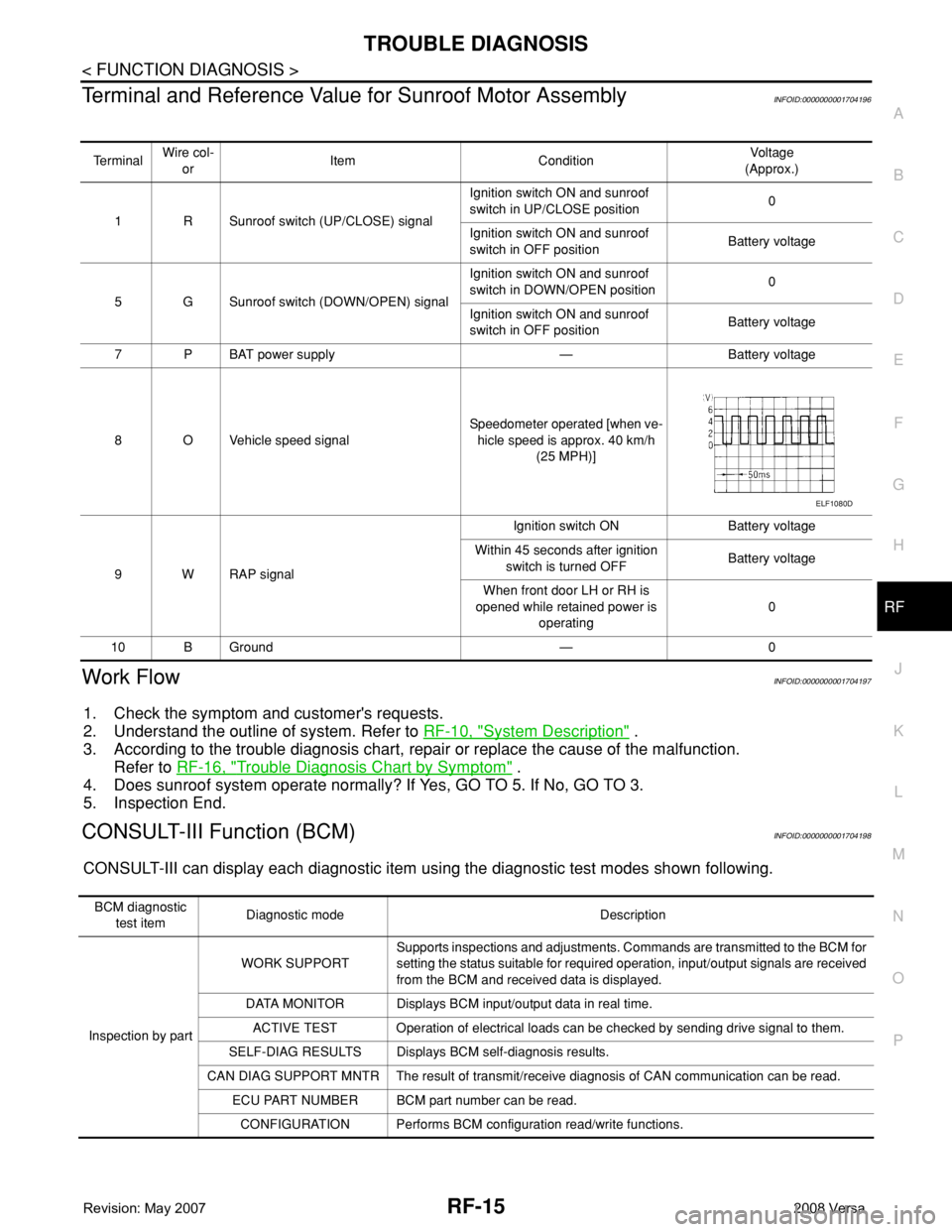
Terminal and Reference Value for Sunroof Motor AssemblyINFOID:0000000001704196
Work FlowINFOID:0000000001704197
1. Check the symptom and customer's requests.
2. Understand the outline of system. Refer to RF-10, "
System Description" .
3. According to the trouble diagnosis chart, repair or replace the cause of the malfunction.
Refer to RF-16, "
Trouble Diagnosis Chart by Symptom" .
4. Does sunroof system operate normally? If Yes, GO TO 5. If No, GO TO 3.
5. Inspection End.
CONSULT-III Function (BCM)INFOID:0000000001704198
CONSULT-III can display each diagnostic item using the diagnostic test modes shown following.
Te r m i n a lWire col-
orItem ConditionVoltag e
(Approx.)
1 R Sunroof switch (UP/CLOSE) signalIgnition switch ON and sunroof
switch in UP/CLOSE position0
Ignition switch ON and sunroof
switch in OFF positionBattery voltage
5 G Sunroof switch (DOWN/OPEN) signalIgnition switch ON and sunroof
switch in DOWN/OPEN position0
Ignition switch ON and sunroof
switch in OFF positionBattery voltage
7PBAT power supply — Battery voltage
8 O Vehicle speed signalSpeedometer operated [when ve-
hicle speed is approx. 40 km/h
(25 MPH)]
9 W RAP signalIgnition switch ON Battery voltage
Within 45 seconds after ignition
switch is turned OFFBattery voltage
When front door LH or RH is
opened while retained power is
operating0
10 B Ground — 0
ELF1080D
BCM diagnostic
test itemDiagnostic mode Description
Inspection by partWORK SUPPORTSupports inspections and adjustments. Commands are transmitted to the BCM for
setting the status suitable for required operation, input/output signals are received
from the BCM and received data is displayed.
DATA MONITOR Displays BCM input/output data in real time.
ACTIVE TEST Operation of electrical loads can be checked by sending drive signal to them.
SELF-DIAG RESULTS Displays BCM self-diagnosis results.
CAN DIAG SUPPORT MNTR The result of transmit/receive diagnosis of CAN communication can be read.
ECU PART NUMBER BCM part number can be read.
CONFIGURATION Performs BCM configuration read/write functions.
Page 2579 of 2771

SB-8
< ON-VEHICLE REPAIR >
SEAT BELTS
• The seat belt was damaged in an accident. (i.e. torn webbing, bent retractor or guide, etc.)
• The seat belt attaching point was damaged in an accident. Inspect the seat belt attaching area for damage
or distortion and repair as necessary before installing a new seat belt assembly.
• Anchor bolts are deformed or worn out.
• The seat belt pre-tensioner should be replaced even if the seat belts are not in use during a frontal collision
in which the air bags are deployed.
PRELIMINARY CHECKS
1. Check the seat belt warning lamp/chime for proper operation as follows:
a. Switch ignition ON. The seat belt warning lamp should illuminate. Also, the seat belt warning chime should
sound for about seven seconds.
b. Fasten driver's seat belt. The seat belt warning lamp should go out and the chime (if sounding) should
stop.
2. If the air bag warning lamp is blinking, conduct self-diagnosis using CONSULT-II, and air bag warning
lamp. Refer to SRS-18, "
SRS Operation Check".
3. Check that the seat belt retractor, seat belt anchor and buckle bolts are securely attached.
4. Check the shoulder seat belt guide and shoulder belt height adjuster for front seats. Make sure guide
swivels freely and that webbing lays flat and does not bind in guide. Make sure height adjuster operates
properly and holds securely.
5. Check retractor operation:
a. Fully extend the seat belt webbing and check for twists, tears or other damage.
b. Allow the seat belt to retract. Make sure that webbing returns smoothly and completely into the retractor. If
the seat belt does not return smoothly, wipe the inside of the loops with a clean paper cloth. Dirt build-up
in the loops of the upper anchors can cause the seat belts to retract slowly.
c. Fasten the seat belt. Check the seat belt returns smoothly and completely to the retractor. If the webbing
does not return smoothly, the cause may be an accumulation of dust or dirt. Use the “SEAT BELT TAPE
SET” and perform the following steps.
Inspect the front seat belt though-anchor 1. Pull the seat belt out to a length of 500 mm (19.69 in) or more.
2. Use a clip or other device to attach the seat belt at the center pillar webbing opening.
3. Pass a thin wire though the D-ring anchor webbing opening. Hold both ends of the wire and pull taut
while moving it up and down several times along the webbing opening surface to remove matter stuck
there.
4. Any dirt that cannot be removed with the wire can be removed by cleaning the opening with a clean
cloth.
5. Apply tape at the point where the webbing contacts the though-anchor webbing opening.
NOTE:
Apply the tape so that there is no looseness or wrinkling.
6. Remove the clip attaching the seat belt and check that the webbing returns smoothly.
6. Repeat steps above as necessary to check the other seat belts.
SEAT BELT RETRACTOR ON-VEHICLE CHECK
Emergency Locking Retractors (ELR) and Automatic Locking Retractors (ALR)
NOTE:
All seat belt retractors are of the Emergency Locking Retractors (ELR) type. In an emergency (sudden stop)
the retractor will lock and prevent the webbing from extending any further. All 3-point type seat belt retractors
except the driver's seat belt also have an Automatic Locking Retractors (ALR) mode. The ALR mode (also
called child restraint mode) is used when installing child seats. The ALR mode is activated when the seat belt
is fully extended. When the webbing is then retracted partially, the ALR mode automatically locks the seat belt
in a specific position so the webbing cannot be extended any further. To cancel the ALR mode, allow the seat
belt to fully wind back into the retractor.
Check the seat belt retractors using the following test(s) to determine if a retractor assembly is operating prop-
erly.
ELR Function Stationary Check
Grasp the shoulder webbing and pull it forward quickly. The retractor should lock and prevent the belt from
extending further.
Page 2651 of 2771
TROUBLE DIAGNOSIS
SRS-17
< SYMPTOM DIAGNOSIS >
C
D
E
F
G
I
J
K
L
MA
B
SRS
N
O
P
HOW TO CHANGE BETWEEN SELF-DIAGNOSIS MODE AND USER MODE WITH CONSULT-III
From User Mode to Diagnosis Mode
After selecting “AIR BAG” on the “SELECT SYSTEM” screen, User mode automatically changes to Diagnosis
mode.
From Diagnosis Mode to User Mode
To return to User mode from Diagnosis mode, touch “BACK” key of CONSULT-III until “SELECT SYSTEM”
appears, Diagnosis mode automatically changes to User mode.
HOW TO ERASE SELF-DIAGNOSIS RESULTS
NOTE:
If the memory in “SELF-DIAG [PAST]” is not erased, User mode will continue to show the system mal-
function by the operation of the warning lamp even if the malfunction is repaired completely.
• “SELF-DIAG [CURRENT]”
A current self-diagnosis result is displayed on the CONSULT-III screen in real time. After the malfunction is
repaired completely, no malfunction is detected on “SELF-DIAG [CURRENT]”.
• “SELF-DIAG [PAST]”
Return to the “SELF-DIAG [CURRENT]” CONSULT-III screen by touching “BACK” key of CONSULT-III and
select “SELF-DIAG [CURRENT]” in SELECT DIAG MODE. Touch “ERASE” in “SELF-DIAG [CURRENT]”
mode.
• “TROUBLE DIAG RECORD”
The memory of “TROUBLE DIAG RECORD” cannot be erased.
Self-Diagnosis Function (Without CONSULT-III)INFOID:0000000001703920
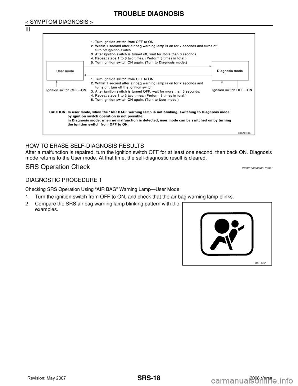
The reading of these results is accomplished using one of two modes —“User mode” and “Diagnosis mode”.
HOW TO CHANGE BETWEEN USER MODE AND SELF-DIAGNOSIS MODE WITHOUT CONSULT-
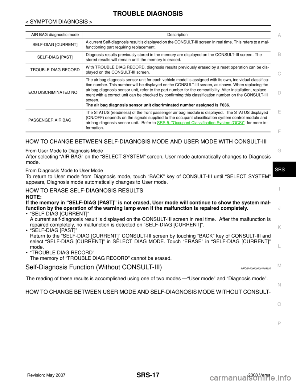
AIR BAG diagnostic mode Description
SELF-DIAG [CURRENT]A current Self-diagnosis result is displayed on the CONSULT-III screen in real time. This refers to a mal-
functioning part requiring replacement.
SELF-DIAG [PAST]Diagnosis results previously stored in the memory are displayed on the CONSULT-III screen. The
stored results will remain until the memory is erased.
TROUBLE DIAG RECORDWith TROUBLE DIAG RECORD, diagnosis results previously erased by a reset operation can be dis-
played on the CONSULT-III screen.
ECU DISCRIMINATED NO.The air bag diagnosis sensor unit for each vehicle model is assigned with its own, individual classifica-
tion number. This number will be displayed on the CONSULT-III screen, as shown. When replacing the
air bag diagnosis sensor unit, refer to the part number for the compatibility. After installation, replace-
ment with a correct unit can be checked by confirming this classification number on the CONSULT-III
screen.
The air bag diagnosis sensor unit discriminated number assigned is F636.
PASSENGER AIR BAGThe STATUS (readiness) of the front passenger air bag module is displayed. The STATUS displayed
(ON/OFF) depends on the signals supplied to the occupant classification system control module and
air bag diagnosis sensor unit. Refer to SRS-5, "
Occupant Classification System (OCS)" for more in-
formation.
Page 2652 of 2771
SRS-18
< SYMPTOM DIAGNOSIS >
TROUBLE DIAGNOSIS
III
HOW TO ERASE SELF-DIAGNOSIS RESULTS
After a malfunction is repaired, turn the ignition switch OFF for at least one second, then back ON. Diagnosis
mode returns to the User mode. At that time, the self-diagnostic result is cleared.
SRS Operation CheckINFOID:0000000001703921
DIAGNOSTIC PROCEDURE 1
Checking SRS Operation Using “AIR BAG” Warning Lamp—User Mode
1. Turn the ignition switch from OFF to ON, and check that the air bag warning lamp blinks.
2. Compare the SRS air bag warning lamp blinking pattern with the
examples.
SHIA0183E
BF-1845D
Page 2658 of 2771

SRS-24
< SYMPTOM DIAGNOSIS >
TROUBLE DIAGNOSIS
2. Touch “TROUBLE DIAG RECORD”.
NOTE:
With “TROUBLE DIAG RECORD”, diagnosis results previously erased by a reset operation can be
displayed.
3. Diagnostic code is displayed on “TROUBLE DIAG RECORD”.
4. Touch “PRINT”.
5. Compare diagnostic codes to "CONSULT-III Diagnostic Code Chart ("SELF-DIAG [PAST]" or "TROUBLE
DIAG RECORD")".
6. Touch “BACK” key of CONSULT-III until “SELECT SYSTEM” appears.
7. Turn ignition switch OFF, then turn off and disconnect CONSULT-III, and both battery cables.
8. Repair the system as outlined by the “Repair order” in “Intermittent Malfunction Diagnostic Code Chart”,
that corresponds to the self-diagnostic result. For replacement procedure of component parts, refer to the
Removal and Installation procedure for the appropriate component.
9. Go to "DIAGNOSTIC PROCEDURE 3", for final checking.
CONSULT-III Diagnostic Code Chart ("SELF-DIAG [PAST]" or "TROUBLE DIAG RECORD")
Diagnostic item ExplanationRepair order
Recheck SRS at each replacement
NO DTC IS DETECTEDWhen malfunction is
indicated by the “AIR
BAG” warning lamp in
User mode.• Low battery voltage (Less than 9V) • Go to "DIAGNOSTIC PROCEDURE
3" .
• Self-diagnostic result “SELF-DIAG
[PAST]” (previously stored in the
memory) might not be erased after
repair.
• Intermittent malfunction has been
detected in the past.• Go to "DIAGNOSTIC PROCEDURE
4" .
• Go to "DIAGNOSTIC PROCEDURE
5" .
• No malfunction is detected. —
DRIVER AIRBAG MODULE
[OPEN]
[B1049] or [B1054]Driver air bag module circuit is open (including the spiral ca-
ble).1. Visually check the wiring harness
connection.
2. Replace the harness if it has visi-
ble damage.
3. Replace driver air bag module.
4. Replace the spiral cable.
5. Replace the air bag diagnosis
sensor unit.
6. Replace the related harness. DRIVER AIRBAG MODULE
[VB-SHORT]
[B1050] or [B1055]Driver air bag module circuit is shorted to some power supply
circuit (including the spiral cable).
DRIVER AIRBAG MODULE
[GND-SHORT]
[B1051] or [B1056]Driver air bag module circuit is shorted to ground (including
the spiral cable).
DRIVER AIRBAG MODULE
[SHORT]
[B1052] or [B1057]Driver air bag module circuits are shorted to each other.
ASSIST A/B MODULE
[OPEN]
[B1065] or [B1070]Front passenger air bag module circuit is open. 1. Visually check the wiring harness
connection.
2. Replace the harness if it has visi-
ble damage.
3. Replace front passenger air bag
module.
4. Replace the air bag diagnosis
sensor unit.
5. Replace the related harness. ASSIST A/B MODULE
[VB-SHORT]
[B1066] or [B1071]Front passenger air bag module circuit is shorted to some
power supply circuit.
ASSIST A/B MODULE
[GND-SHORT]
[B1067] or [B1072]Front passenger air bag module circuit is shorted to ground.
ASSIST A/B MODULE
[SHORT]
[B1068] or [B1073]Front passenger air bag module circuits are shorted to each
other.