Page 1978 of 2771
![NISSAN LATIO 2008 Service Repair Manual IP-12
< ON-VEHICLE REPAIR >
INSTRUMENT PANEL ASSEMBLY
[ ]: Number indicates step in removal procedures.
INSTRUMENT PANEL ASSEMBLY
Removal
1. Pull instrument finisher E backward by approximately 30
deg NISSAN LATIO 2008 Service Repair Manual IP-12
< ON-VEHICLE REPAIR >
INSTRUMENT PANEL ASSEMBLY
[ ]: Number indicates step in removal procedures.
INSTRUMENT PANEL ASSEMBLY
Removal
1. Pull instrument finisher E backward by approximately 30
deg](/manual-img/5/57360/w960_57360-1977.png)
IP-12
< ON-VEHICLE REPAIR >
INSTRUMENT PANEL ASSEMBLY
[ ]: Number indicates step in removal procedures.
INSTRUMENT PANEL ASSEMBLY
Removal
1. Pull instrument finisher E backward by approximately 30
degrees while disengaging the instrument finisher E metal clips
and pawl.
Glove box assembly"GLOVE
BOX AS-
SEMBLY"[ 15 ]
Side ventilator assembly (RH)IP-10
[ 16 ] [ 4 ]
Passenger air bag module assemblySRS-38
[ 17 ] [ 5 ]
Instrument upper maskIP-10
[ 18 ]
Instrument finisher DIP-10
[ 19 ]
Controller MTC-55
[ 20 ]
Instrument upper panel assembly IP-10
[ 21 ]
Console mask"Remov-
al"[ 22 ] [ 1 ]
CVT, A/T console finisherIP-23
[ 23 ] [ 2 ]
M/T console bootIP-23
[ 23 ] [ 2 ]
Console rear finisherIP-23
[ 24 ] [ 3 ]
Console mask cover (with arm rest)IP-23
[ 25 ] [ 4 ]
Rear cup holder (without arm rest)IP-23
[ 25 ] [ 4 ]
Console body assemblyIP-23
[ 26 ] [ 5 ]
Instrument lower cover (LH/RH)"INSTRU-
MENT
LOWER
FINISH-
ER"[ 27 ] [ 6 ]
Center console assembly"CEN-
TER
CON-
SOLE AS-
SEMBLY"[ 28 ] [ 7 ]
Fuse block lidIP-10
[ 29 ]
Lighting and turn signal switchLT- 6 0
[ 30 ]
Wiper & washer switchWW-22
[ 31 ]
Instrument panel & padIP-10
[ 32 ] PartsReference
pageInstrument
panel and padCluster lid A Cluster lid C Passenger air
bag module
assemblyCenter con-
sole assembly
WIIA1224E
Page 1988 of 2771

IP-22
< ON-VEHICLE REPAIR >
INSTRUMENT PANEL ASSEMBLY
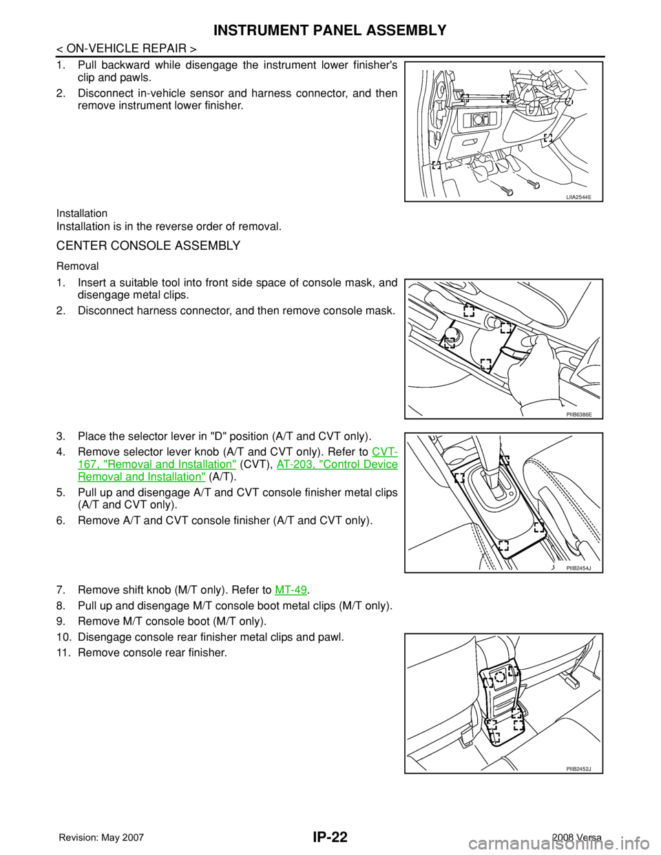
1. Pull backward while disengage the instrument lower finisher's
clip and pawls.
2. Disconnect in-vehicle sensor and harness connector, and then
remove instrument lower finisher.
Installation
Installation is in the reverse order of removal.
CENTER CONSOLE ASSEMBLY
Removal
1. Insert a suitable tool into front side space of console mask, and
disengage metal clips.
2. Disconnect harness connector, and then remove console mask.
3. Place the selector lever in "D" position (A/T and CVT only).
4. Remove selector lever knob (A/T and CVT only). Refer to CVT-
167, "Removal and Installation" (CVT), AT-203, "Control Device
Removal and Installation" (A/T).
5. Pull up and disengage A/T and CVT console finisher metal clips
(A/T and CVT only).
6. Remove A/T and CVT console finisher (A/T and CVT only).
7. Remove shift knob (M/T only). Refer to MT-49
.
8. Pull up and disengage M/T console boot metal clips (M/T only).
9. Remove M/T console boot (M/T only).
10. Disengage console rear finisher metal clips and pawl.
11. Remove console rear finisher.
LIIA2544E
PIIB6386E
PIIB2454J
PIIB2452J
Page 1989 of 2771
INSTRUMENT PANEL ASSEMBLY
IP-23
< ON-VEHICLE REPAIR >
C
D
E
F
G
H
J
K
L
MA
B
IP
N
O
P
12. Disengage console mask cover metal clips and pawls, and then
remove console mask cover (with armrest).
13. Disengage rear cup holder metal clips and pawls (without arm-
rest).
14. Remover rear cup holder (without armrest).
15. Remove console body assembly screws and nut.
16. Disconnect harness connector, and then remove console body assembly.
17. Remove both of the instrument lower cover LH and RH clips.
18. Disengage instrument lower cover LH and RH metal clips and
remove both of the instrument lower cover LH and RH.
19. Remove screws and then remove center console.
Installation
Installation is in the reverse order of removal.
Disassembly and AssemblyINFOID:0000000001704253
GLOVE BOX ASSEMBLY
PIIB6387E
PIIB6388E
PIIB2882J
Page 1990 of 2771
IP-24
< ON-VEHICLE REPAIR >
INSTRUMENT PANEL ASSEMBLY
Disassembly
1. Remove screws of damper, and then remove damper.
2. Remove screws of glove box striker, and then remove glove box striker.
3. Remove screws of glove box latch, and then remove glove box latch.
Assembly
Assembly is in the reverse order of disassembly.
CENTER CONSOLE ASSEMBLY
1. Glove box striker 2. Glove box 3. Glove box latch
4. Damper
LIIA2555E
Page 1991 of 2771
INSTRUMENT PANEL ASSEMBLY
IP-25
< ON-VEHICLE REPAIR >
C
D
E
F
G
H
J
K
L
MA
B
IP
N
O
P Disassembly
Remove the four screws, and then remove front cup holder from center console.
Assembly
Assembly is in the reverse order of disassembly.
COMBINATION METER
Disassembly
Disengage the eight tabs to separate front cover (1) from the unified
meter control unit assembly (2).
Assembly
Assembly is in the reverse order of disassembly.
1. Center console 2. Front cup holder
LIIA2556E
LIIA2582E
Page 2302 of 2771

MT-14
< SERVICE INFORMATION >
CONTROL LINKAGE
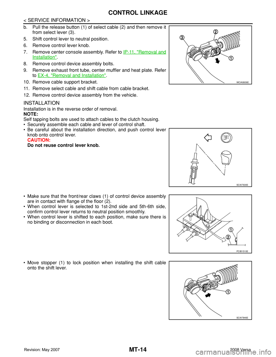
b. Pull the release button (1) of select cable (2) and then remove it
from select lever (3).
5. Shift control lever to neutral position.
6. Remove control lever knob.
7. Remove center console assembly. Refer to IP-11, "
Removal and
Installation".
8. Remove control device assembly bolts.
9. Remove exhaust front tube, center muffler and heat plate. Refer
to EX-4, "
Removal and Installation".
10. Remove cable support bracket.
11. Remove select cable and shift cable from cable bracket.
12. Remove control device assembly from the vehicle.
INSTALLATION
Installation is in the reverse order of removal.
NOTE:
Self tapping bolts are used to attach cables to the clutch housing.
• Securely assemble each cable and lever of control shaft.
• Be careful about the installation direction, and push control lever
knob onto control lever.
CAUTION:
Do not reuse control lever knob.
• Make sure that the front/rear claws (1) of control device assembly
are in contact with flange of the floor (2).
• When control lever is selected to 1st-2nd side and 5th-6th side,
confirm control lever returns to neutral position smoothly.
• When control lever is shifted to each position, make sure there is
no binding or disconnection in each boot.
• Move stopper (1) to lock position when installing the shift cable
onto the shift lever.
WCIA0606E
SCIA7630E
PCIB1510E
SCIA7846E
Page 2410 of 2771
MTC-72
< SERVICE INFORMATION >
DUCTS AND GRILLES
CENTER VENTILATOR DUCTS
Removal
1. Remove instrument panel & pad. Refer to IP-10.
2. Remove screws (A), and then remove center ventilator ducts
(1).
Installation
Installation is in the reverse order of removal.
SIDE FOOT DUCTS
NOTE:
The side foot ducts are part of the A/C unit assembly case.
Removal
1. Remove A/C unit assembly. Refer to MTC-58.
2. Remove screws (A), and then remove side foot duct (LH) (1).
3. Remove screws (A), and then remove side foot duct (RH) (1).
Installation
Installation is in the reverse order of removal.
FLOOR DUCTS
Removal
1. Remove front seats and center console assembly. Refer to SE-10 and IP-10.
SJIA0663E
SJIA0664E
SJIA0665E
Page 2431 of 2771

PARKING BRAKE CONTROL
PB-5
< SERVICE INFORMATION >
C
D
E
G
H
I
J
K
L
MA
B
PB
N
O
P
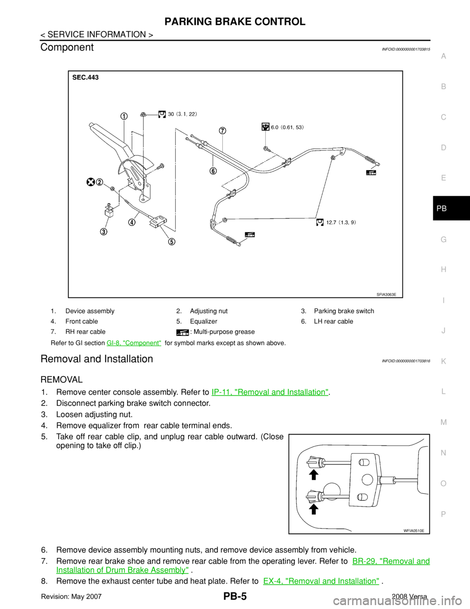
ComponentINFOID:0000000001703815
Removal and InstallationINFOID:0000000001703816
REMOVAL
1. Remove center console assembly. Refer to IP-11, "Removal and Installation".
2. Disconnect parking brake switch connector.
3. Loosen adjusting nut.
4. Remove equalizer from rear cable terminal ends.
5. Take off rear cable clip, and unplug rear cable outward. (Close
opening to take off clip.)
6. Remove device assembly mounting nuts, and remove device assembly from vehicle.
7. Remove rear brake shoe and remove rear cable from the operating lever. Refer to BR-29, "
Removal and
Installation of Drum Brake Assembly" .
8. Remove the exhaust center tube and heat plate. Refer to EX-4, "
Removal and Installation" .
1. Device assembly 2. Adjusting nut 3. Parking brake switch
4. Front cable 5. Equalizer 6. LH rear cable
7. RH rear cable : Multi-purpose grease
Refer to GI section GI-8, "
Component" for symbol marks except as shown above.
SFIA3063E
WFIA0510E