2008 NISSAN LATIO battery
[x] Cancel search: batteryPage 1101 of 2771

AIR CONDITIONING CUT CONTROL
EC-27
< SERVICE INFORMATION >
C
D
E
F
G
H
I
J
K
L
MA
EC
N
P O
AIR CONDITIONING CUT CONTROL
Input/Output Signal ChartINFOID:0000000001702558
*1: This signal is sent to the ECM through CAN communication line.
*2: ECM determines the start signal status by the signals of engine speed and battery voltage.
System DescriptionINFOID:0000000001702559
This system improves engine operation when the air conditioner is used.
Under the following conditions, the air conditioner is turned off.
• When the accelerator pedal is fully depressed.
• When cranking the engine.
• At high engine speeds.
• When the engine coolant temperature becomes excessively high.
• When operating power steering during low engine speed or low vehicle speed.
• When engine speed is excessively low.
• When refrigerant pressure is excessively low or high.
Sensor Input Signal to ECM ECM function Actuator
Air conditioner switch
Air conditioner ON signal*
1
Air conditioner
cut controlAir conditioner relay Accelerator pedal position sensor Accelerator pedal position
Crankshaft position sensor (POS)
Camshaft position sensor (PHASE)Engine speed*
2
Engine coolant temperature sensor Engine coolant temperature
Battery
Battery voltage*
2
Refrigerant pressure sensor Refrigerant pressure
EPS control unit
Power steering operation*
1
Wheel sensor
Vehicle speed*1
Page 1111 of 2771

EVAPORATIVE EMISSION SYSTEM
EC-37
< SERVICE INFORMATION >
C
D
E
F
G
H
I
J
K
L
MA
EC
N
P O
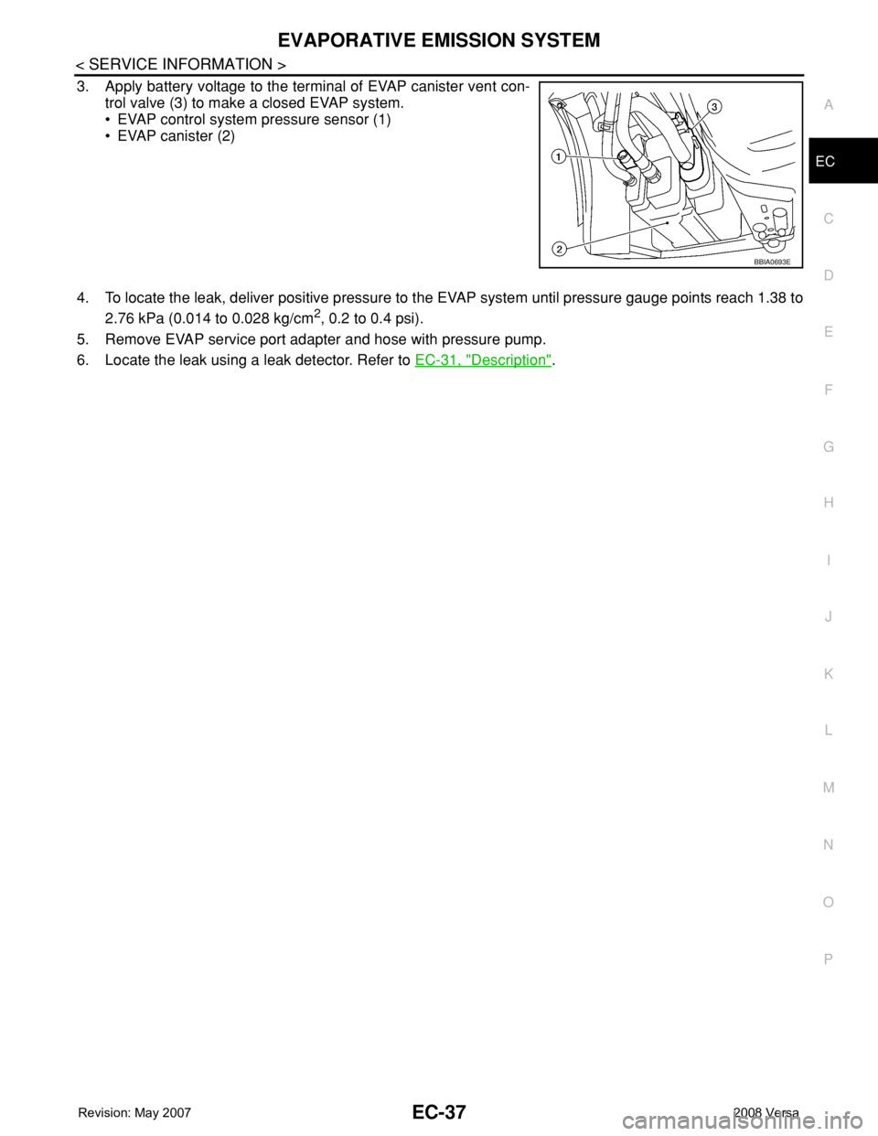
3. Apply battery voltage to the terminal of EVAP canister vent con-
trol valve (3) to make a closed EVAP system.
• EVAP control system pressure sensor (1)
• EVAP canister (2)
4. To locate the leak, deliver positive pressure to the EVAP system until pressure gauge points reach 1.38 to
2.76 kPa (0.014 to 0.028 kg/cm
2, 0.2 to 0.4 psi).
5. Remove EVAP service port adapter and hose with pressure pump.
6. Locate the leak using a leak detector. Refer to EC-31, "
Description".
BBIA0693E
Page 1112 of 2771

EC-38
< SERVICE INFORMATION >
ON BOARD REFUELING VAPOR RECOVERY (ORVR)
ON BOARD REFUELING VAPOR RECOVERY (ORVR)
System DescriptionINFOID:0000000001702567
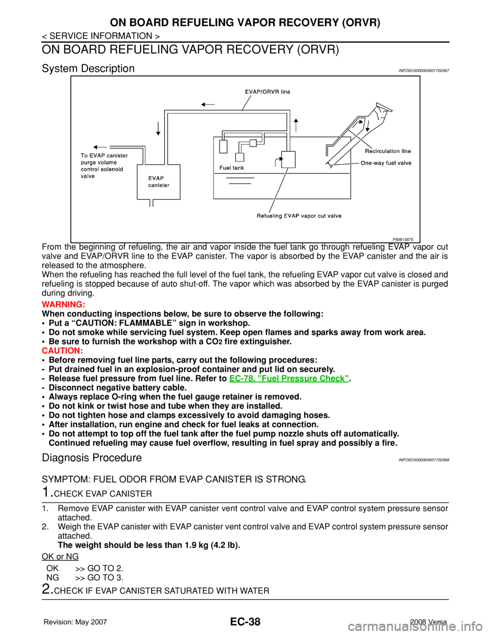
From the beginning of refueling, the air and vapor inside the fuel tank go through refueling EVAP vapor cut
valve and EVAP/ORVR line to the EVAP canister. The vapor is absorbed by the EVAP canister and the air is
released to the atmosphere.
When the refueling has reached the full level of the fuel tank, the refueling EVAP vapor cut valve is closed and
refueling is stopped because of auto shut-off. The vapor which was absorbed by the EVAP canister is purged
during driving.
WARNING:
When conducting inspections below, be sure to observe the following:
• Put a “CAUTION: FLAMMABLE” sign in workshop.
• Do not smoke while servicing fuel system. Keep open flames and sparks away from work area.
• Be sure to furnish the workshop with a CO
2 fire extinguisher.
CAUTION:
• Before removing fuel line parts, carry out the following procedures:
- Put drained fuel in an explosion-proof container and put lid on securely.
- Release fuel pressure from fuel line. Refer to EC-78, "
Fuel Pressure Check".
- Disconnect negative battery cable.
• Always replace O-ring when the fuel gauge retainer is removed.
• Do not kink or twist hose and tube when they are installed.
• Do not tighten hose and clamps excessively to avoid damaging hoses.
• After installation, run engine and check for fuel leaks at connection.
• Do not attempt to top off the fuel tank after the fuel pump nozzle shuts off automatically.
Continued refueling may cause fuel overflow, resulting in fuel spray and possibly a fire.
Diagnosis ProcedureINFOID:0000000001702568
SYMPTOM: FUEL ODOR FROM EVAP CANISTER IS STRONG.
1.CHECK EVAP CANISTER
1. Remove EVAP canister with EVAP canister vent control valve and EVAP control system pressure sensor
attached.
2. Weigh the EVAP canister with EVAP canister vent control valve and EVAP control system pressure sensor
attached.
The weight should be less than 1.9 kg (4.2 lb).
OK or NG
OK >> GO TO 2.
NG >> GO TO 3.
2.CHECK IF EVAP CANISTER SATURATED WITH WATER
PBIB1387E
Page 1134 of 2771

EC-60
< SERVICE INFORMATION >
ON BOARD DIAGNOSTIC (OBD) SYSTEM
2. Perform AT-36, "OBD-II Diagnostic Trouble Code (DTC)" or "How to Erase DTC". (The DTC in the TCM
will be erased.)
3. Change the diagnostic test mode from Mode II to Mode I by depressing the accelerator pedal.
Refer to EC-60, "
Malfunction Indicator Lamp (MIL)".
•If the battery is disconnected, the emission-related diagnostic information will be lost within 24
hours.
•The following data are cleared when the ECM memory is erased.
- Diagnostic trouble codes
- 1st trip diagnostic trouble codes
- Freeze frame data
- 1st trip freeze frame data
- System readiness test (SRT) codes
- Test values
Actual work procedures are explained using a DTC as an example. Be careful so that not only the DTC, but all
of the data listed above, are cleared from the ECM memory during work procedures.
Malfunction Indicator Lamp (MIL)INFOID:0000000001702576
DESCRIPTION
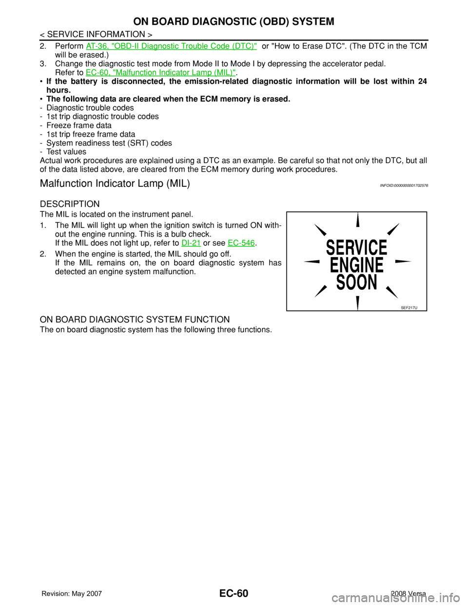
The MIL is located on the instrument panel.
1. The MIL will light up when the ignition switch is turned ON with-
out the engine running. This is a bulb check.
If the MIL does not light up, refer to DI-21
or see EC-546.
2. When the engine is started, the MIL should go off.
If the MIL remains on, the on board diagnostic system has
detected an engine system malfunction.
ON BOARD DIAGNOSTIC SYSTEM FUNCTION
The on board diagnostic system has the following three functions.
SEF217U
Page 1137 of 2771

ON BOARD DIAGNOSTIC (OBD) SYSTEM
EC-63
< SERVICE INFORMATION >
C
D
E
F
G
H
I
J
K
L
MA
EC
N
P O
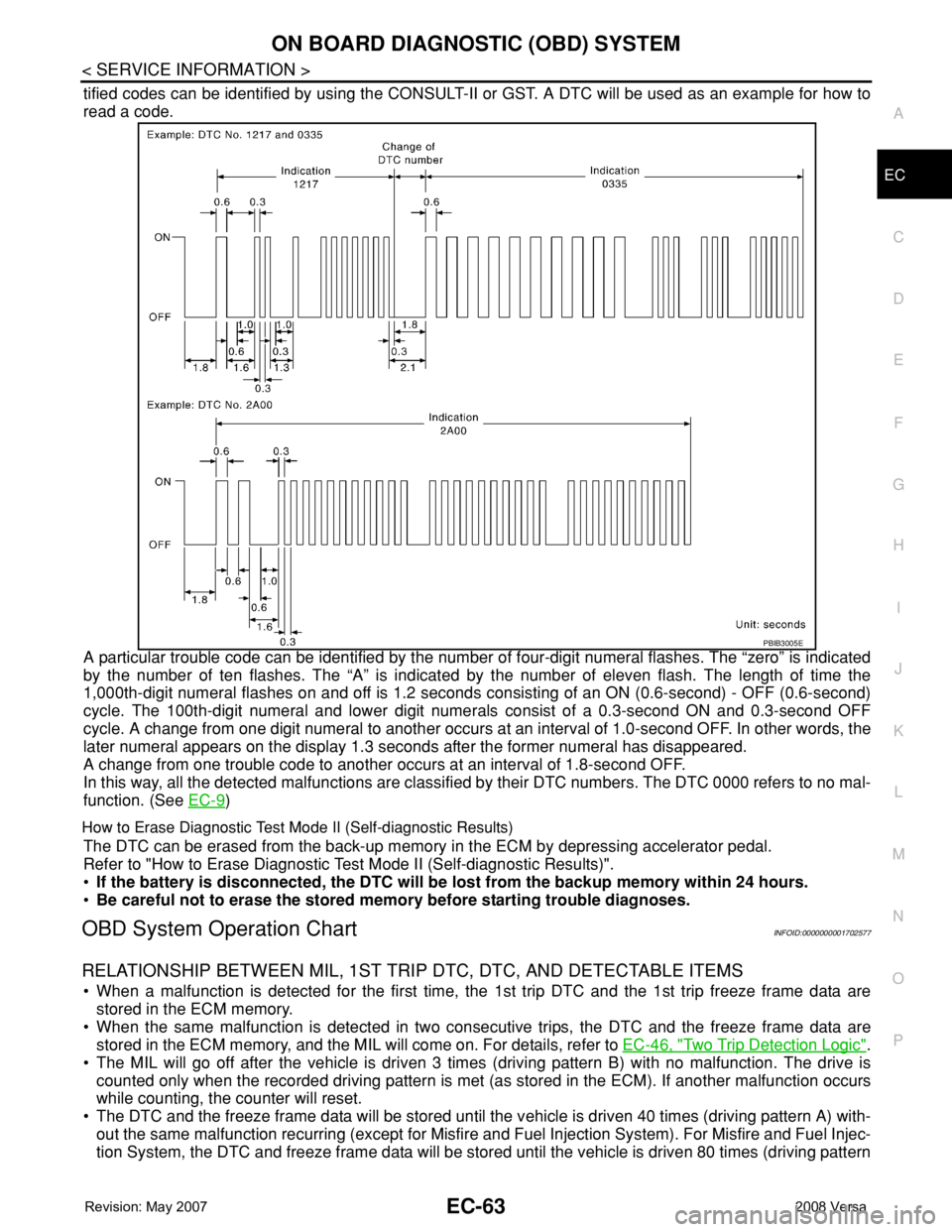
tified codes can be identified by using the CONSULT-II or GST. A DTC will be used as an example for how to
read a code.
A particular trouble code can be identified by the number of four-digit numeral flashes. The “zero” is indicated
by the number of ten flashes. The “A” is indicated by the number of eleven flash. The length of time the
1,000th-digit numeral flashes on and off is 1.2 seconds consisting of an ON (0.6-second) - OFF (0.6-second)
cycle. The 100th-digit numeral and lower digit numerals consist of a 0.3-second ON and 0.3-second OFF
cycle. A change from one digit numeral to another occurs at an interval of 1.0-second OFF. In other words, the
later numeral appears on the display 1.3 seconds after the former numeral has disappeared.
A change from one trouble code to another occurs at an interval of 1.8-second OFF.
In this way, all the detected malfunctions are classified by their DTC numbers. The DTC 0000 refers to no mal-
function. (See EC-9
)
How to Erase Diagnostic Test Mode II (Self-diagnostic Results)
The DTC can be erased from the back-up memory in the ECM by depressing accelerator pedal.
Refer to "How to Erase Diagnostic Test Mode II (Self-diagnostic Results)".
•If the battery is disconnected, the DTC will be lost from the backup memory within 24 hours.
•Be careful not to erase the stored memory before starting trouble diagnoses.
OBD System Operation ChartINFOID:0000000001702577
RELATIONSHIP BETWEEN MIL, 1ST TRIP DTC, DTC, AND DETECTABLE ITEMS
• When a malfunction is detected for the first time, the 1st trip DTC and the 1st trip freeze frame data are
stored in the ECM memory.
• When the same malfunction is detected in two consecutive trips, the DTC and the freeze frame data are
stored in the ECM memory, and the MIL will come on. For details, refer to EC-46, "
Two Trip Detection Logic".
• The MIL will go off after the vehicle is driven 3 times (driving pattern B) with no malfunction. The drive is
counted only when the recorded driving pattern is met (as stored in the ECM). If another malfunction occurs
while counting, the counter will reset.
• The DTC and the freeze frame data will be stored until the vehicle is driven 40 times (driving pattern A) with-
out the same malfunction recurring (except for Misfire and Fuel Injection System). For Misfire and Fuel Injec-
tion System, the DTC and freeze frame data will be stored until the vehicle is driven 80 times (driving pattern
PBIB3005E
Page 1150 of 2771

EC-76
< SERVICE INFORMATION >
BASIC SERVICE PROCEDURE
Accelerator Pedal Released Position Learning
INFOID:0000000001702582
DESCRIPTION
Accelerator Pedal Released Position Learning is an operation to learn the fully released position of the accel-
erator pedal by monitoring the accelerator pedal position sensor output signal. It must be performed each time
harness connector of accelerator pedal position sensor or ECM is disconnected.
OPERATION PROCEDURE
1. Make sure that accelerator pedal is fully released.
2. Turn ignition switch ON and wait at least 2 seconds.
3. Turn ignition switch OFF and wait at least 10 seconds.
4. Turn ignition switch ON and wait at least 2 seconds.
5. Turn ignition switch OFF and wait at least 10 seconds.
Throttle Valve Closed Position LearningINFOID:0000000001702583
DESCRIPTION
Throttle Valve Closed Position Learning is an operation to learn the fully closed position of the throttle valve by
monitoring the throttle position sensor output signal. It must be performed each time harness connector of
electric throttle control actuator or ECM is disconnected.
OPERATION PROCEDURE
1. Make sure that accelerator pedal is fully released.
2. Turn ignition switch ON.
3. Turn ignition switch OFF and wait at least 10 seconds.
Make sure that throttle valve moves during above 10 seconds by confirming the operating sound.
Idle Air Volume LearningINFOID:0000000001702584
DESCRIPTION
Idle Air Volume Learning is an operation to learn the idle air volume that keeps each engine within the specific
range. It must be performed under any of the following conditions:
• Each time electric throttle control actuator or ECM is replaced.
• Idle speed or ignition timing is out of specification.
PREPARATION
Before performing Idle Air Volume Learning, make sure that all of the following conditions are satisfied.
Learning will be cancelled if any of the following conditions are missed for even a moment.
• Battery voltage: More than 12.9V (At idle)
• Engine coolant temperature: 70 - 95°C (158 - 203°F)
• Park/neutral position (PNP) switch: ON
• Electric load switch: OFF
[Air conditioner, headlamp, rear window defogger]
On vehicles equipped with daytime light systems, if the parking brake is applied before the engine is
started the headlamp will not be illuminated.
• Steering wheel: Neutral (Straight-ahead position)
• Vehicle speed: Stopped
• Transmission: Warmed-up
- Models with CONSULT-II (A/T and CVT models)
• Drive vehicle until “FLUID TEMP SE” in “DATA MONITOR” mode of “A/T” or “CVT” system indicates less
than 0.9V.
- Models without CONSULT-II (A/T and CVT models) and M/T models
• Drive vehicle for 10 minutes.
OPERATION PROCEDURE
With CONSULT-II
1. Perform EC-76, "Accelerator Pedal Released Position Learning".
2. Perform EC-76, "
Throttle Valve Closed Position Learning".
Page 1163 of 2771

TROUBLE DIAGNOSIS
EC-89
< SERVICE INFORMATION >
C
D
E
F
G
H
I
J
K
L
MA
EC
N
P O
SYMPTOM
Reference
page
HARD/NO START/RESTART (EXCP. HA)
ENGINE STALL
HESITATION/SURGING/FLAT SPOT
SPARK KNOCK/DETONATION
LACK OF POWER/POOR ACCELERATION
HIGH IDLE/LOW IDLE
ROUGH IDLE/HUNTING
IDLING VIBRATION
SLOW/NO RETURN TO IDLE
OVERHEATS/WATER TEMPERATURE HIGH
EXCESSIVE FUEL CONSUMPTION
EXCESSIVE OIL CONSUMPTION
BATTERY DEAD (UNDER CHARGE)
Warranty symptom code AA AB AC AD AE AF AG AH AJ AK AL AM HA
Fuel Fuel pump circuit 11232 22 3 2EC-526
Fuel pressure regulator system 334444444 4EC-78
Fuel injector circuit 11232 22 2EC-521
Evaporative emission system 334444444 4EC-31
Air Positive crankcase ventilation sys-
tem
334444444 41EC-43
Incorrect idle speed adjustment 1 1 1 1 1EC-69
Electric throttle control actuator 112332222 2 2EC-461,
EC-472
IgnitionIncorrect ignition timing adjustment33111 11 1EC-69
Ignition circuit 11222 22 2EC-531
Main power supply and ground circuit 22333 33 23EC-137
Mass air flow sensor circuit
1
122
222 2EC-167,
EC-175
Engine coolant temperature sensor circuit
333EC-187,
EC-198
Air fuel ratio (A/F) sensor 1 circuitEC-206
,
EC-213
,
EC-219
,
EC-225
,
EC-500
Throttle position sensor circuit
22EC-192
,
EC-278
,
EC-426
,
EC-428
,
EC-487
Accelerator pedal position sensor circuit 3 2 1EC-400
,
EC-474
,
EC-480
,
EC-493
Knock sensor circuit 2 3EC-291
Crankshaft position sensor (POS) circuit 2 2EC-295
Camshaft position sensor (PHASE) circuit 3 2EC-302
Vehicle speed signal circuit 2 3 3 3EC-391
ECM 22333333333EC-397
Page 1164 of 2771

EC-90
< SERVICE INFORMATION >
TROUBLE DIAGNOSIS
1 - 6: The numbers refer to the order of inspection.
(continued on next page)
SYSTEM — ENGINE MECHANICAL & OTHER
Intake valve timing control solenoid valve cir-
cuit32 13223 3EC-162
Park/neutral position (PNP) switch circuit 3 3 3 3 3EC-405
Refrigerant pressure sensor circuit 2 3 3 4EC-541
Electrical load signal circuit 3EC-519
Air conditioner circuit 223333333 3 2MTC-22
ABS actuator and electric unit (control unit) 4BRC-8
SYMPTOM
Reference
page
HARD/NO START/RESTART (EXCP. HA)
ENGINE STALL
HESITATION/SURGING/FLAT SPOT
SPARK KNOCK/DETONATION
LACK OF POWER/POOR ACCELERATION
HIGH IDLE/LOW IDLE
ROUGH IDLE/HUNTING
IDLING VIBRATION
SLOW/NO RETURN TO IDLE
OVERHEATS/WATER TEMPERATURE HIGH
EXCESSIVE FUEL CONSUMPTION
EXCESSIVE OIL CONSUMPTION
BATTERY DEAD (UNDER CHARGE)
Warranty symptom code AA AB AC AD AE AF AG AH AJ AK AL AM HA
Fuel Fuel tank
5
5FL-9
Fuel piping 5 5 5 5 5 5EM-33
Va p o r l o c k—
Valve deposit
5 555 55 5—
Poor fuel (Heavy weight gasoline,
Low octane)—