2008 NISSAN LATIO battery
[x] Cancel search: batteryPage 907 of 2771
CVT-68
< SERVICE INFORMATION >
DTC P0705 PARK/NEUTRAL POSITION SWITCH
Diagnosis Procedure
INFOID:0000000001703495
1. CHECK PNP SW SIGNALS
With CONSULT-III
1. Turn ignition switch ON. (Do not start engine.)
2. Select “ECU INPUT SIGNALS” in “DATA MONITOR” mode for “TRANSMISSION” with CONSULT-III.
3. Change selector lever to “P”, “R”, “N”, “D” and “L” positions to check the value of “INH SW1”“INH SW2”
“INH SW3”“INH SW4” and “INH SW3M”.
Without CONSULT-III
1. Turn ignition switch ON. (Do not start engine.)
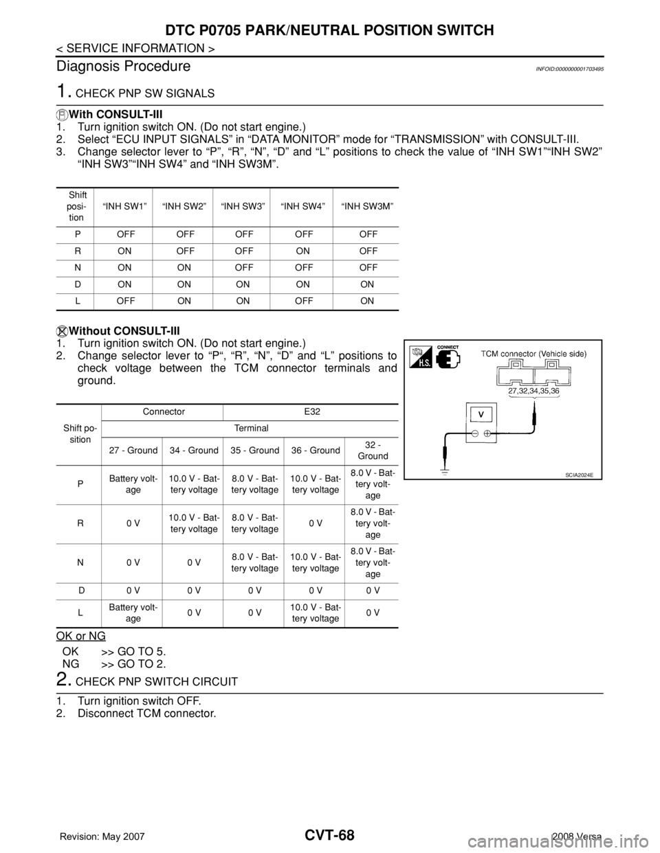
2. Change selector lever to “P“, “R”, “N”, “D” and “L” positions to
check voltage between the TCM connector terminals and
ground.
OK or NG
OK >> GO TO 5.
NG >> GO TO 2.
2. CHECK PNP SWITCH CIRCUIT
1. Turn ignition switch OFF.
2. Disconnect TCM connector.
Shift
posi-
tion“INH SW1” “INH SW2” “INH SW3” “INH SW4” “INH SW3M”
P OFF OFF OFF OFF OFF
R ON OFF OFF ON OFF
N ON ON OFF OFF OFF
DON ON ON ON ON
L OFF ON ON OFF ON
Shift po-
sitionConnector E32
Te r m i n a l
27 - Ground 34 - Ground 35 - Ground 36 - Ground32 -
Ground
PBattery volt-
age10.0 V - Bat-
tery voltage8.0 V - Bat-
tery voltage10.0 V - Bat-
tery voltage8.0 V - Bat-
tery volt-
age
R0 V10.0 V - Bat-
tery voltage8.0 V - Bat-
tery voltage0 V8.0 V - Bat-
tery volt-
age
N0 V 0 V8.0 V - Bat-
tery voltage10.0 V - Bat-
tery voltage8.0 V - Bat-
tery volt-
age
D 0 V 0 V 0 V 0 V 0 V
LBattery volt-
age0 V 0 V10.0 V - Bat-
tery voltage0 V
SCIA2024E
Page 917 of 2771
CVT-78
< SERVICE INFORMATION >
DTC P0715 INPUT SPEED SENSOR CIRCUIT (PRI SPEED SENSOR)
Diagnosis Procedure
INFOID:0000000001703511
1.CHECK INPUT SIGNALS
With CONSULT-III
1. Start engine.
2. Select “ECU INPUT SIGNALS” in “DATA MONITOR” mode for “TRANSMISSION” with CONSULT-III.
3. Start vehicle and read out the value of “PRI SPEED SEN”.
OK or NG
OK >> GO TO 6.
NG >> GO TO 2.
2.CHECK INPUT SPEED SENSOR (PRIMARY SPEED SENSOR)
1. Start engine.
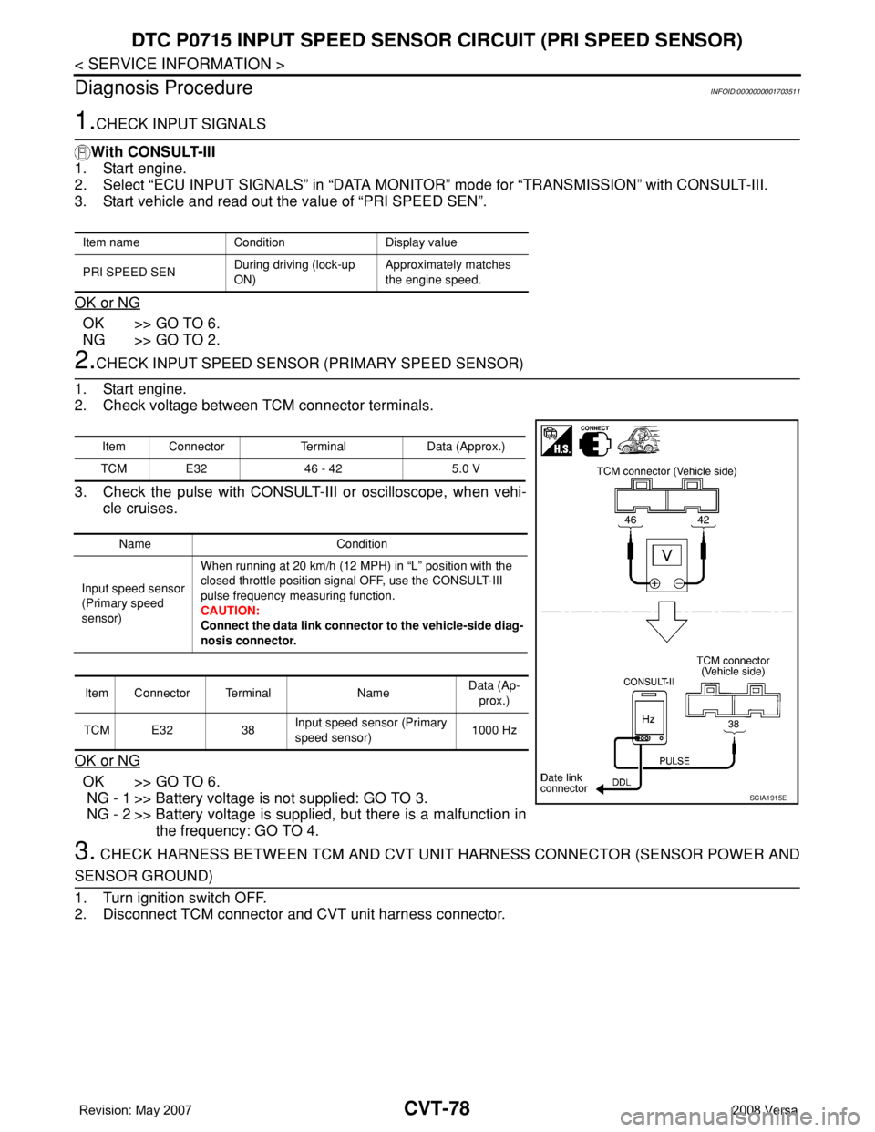
2. Check voltage between TCM connector terminals.
3. Check the pulse with CONSULT-III or oscilloscope, when vehi-
cle cruises.
OK or NG
OK >> GO TO 6.
NG - 1 >> Battery voltage is not supplied: GO TO 3.
NG - 2 >> Battery voltage is supplied, but there is a malfunction in
the frequency: GO TO 4.
3. CHECK HARNESS BETWEEN TCM AND CVT UNIT HARNESS CONNECTOR (SENSOR POWER AND
SENSOR GROUND)
1. Turn ignition switch OFF.
2. Disconnect TCM connector and CVT unit harness connector.
Item name Condition Display value
PRI SPEED SENDuring driving (lock-up
ON)Approximately matches
the engine speed.
Item Connector Terminal Data (Approx.)
TCM E32 46 - 42 5.0 V
Name Condition
Input speed sensor
(Primary speed
sensor)When running at 20 km/h (12 MPH) in “L” position with the
closed throttle position signal OFF, use the CONSULT-III
pulse frequency measuring function.
CAUTION:
Connect the data link connector to the vehicle-side diag-
nosis connector.
Item Connector Terminal NameData (Ap-
prox.)
TCM E32 38Input speed sensor (Primary
speed sensor)1000 Hz
SCIA1915E
Page 921 of 2771
CVT-82
< SERVICE INFORMATION >
DTC P0720 VEHICLE SPEED SENSOR CVT (SECONDARY SPEED SENSOR)
Diagnosis Procedure
INFOID:0000000001703518
1.CHECK INPUT SIGNAL
With CONSULT-III
1. Start engine.
2. Select “ECU INPUT SIGNALS” in “DATA MONITOR” mode for “TRANSMISSION” with CONSULT-III.
3. Start vehicle and read out the value of “VSP SENSOR”.
OK or NG
OK >> GO TO 8.
NG >> GO TO 2.
2. CHECK SECONDARY SPEED SENSOR
With CONSULT-III
1. Start engine.
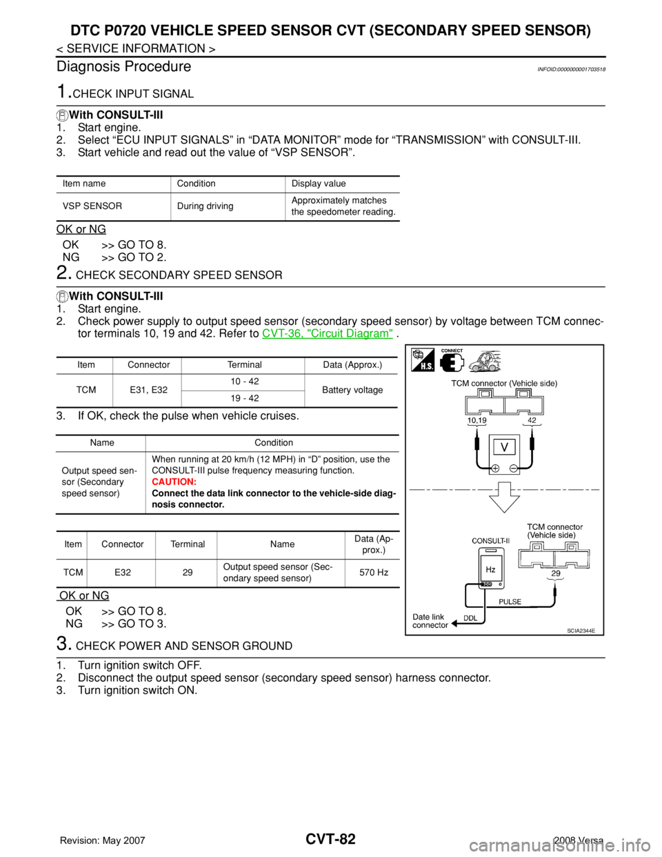
2. Check power supply to output speed sensor (secondary speed sensor) by voltage between TCM connec-
tor terminals 10, 19 and 42. Refer to CVT-36, "
Circuit Diagram" .
3. If OK, check the pulse when vehicle cruises.
OK or NG
OK >> GO TO 8.
NG >> GO TO 3.
3. CHECK POWER AND SENSOR GROUND
1. Turn ignition switch OFF.
2. Disconnect the output speed sensor (secondary speed sensor) harness connector.
3. Turn ignition switch ON.
Item name Condition Display value
VSP SENSOR During drivingApproximately matches
the speedometer reading.
Item Connector Terminal Data (Approx.)
TCM E31, E3210 - 42
Battery voltage
19 - 42
Name Condition
Output speed sen-
sor (Secondary
speed sensor)When running at 20 km/h (12 MPH) in “D” position, use the
CONSULT-III pulse frequency measuring function.
CAUTION:
Connect the data link connector to the vehicle-side diag-
nosis connector.
Item Connector Terminal NameData (Ap-
prox.)
TCM E32 29Output speed sensor (Sec-
ondary speed sensor)570 Hz
SCIA2344E
Page 922 of 2771
DTC P0720 VEHICLE SPEED SENSOR CVT (SECONDARY SPEED SENSOR)
CVT-83
< SERVICE INFORMATION >
D
E
F
G
H
I
J
K
L
MA
B
CVT
N
O
P
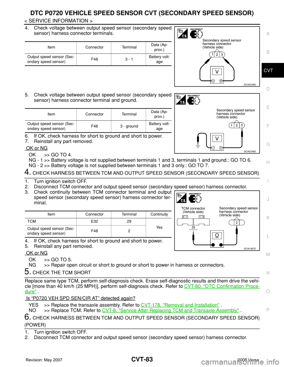
4. Check voltage between output speed sensor (secondary speed
sensor) harness connector terminals.
5. Check voltage between output speed sensor (secondary speed
sensor) harness connector terminal and ground.
6. If OK, check harness for short to ground and short to power.
7. Reinstall any part removed.
OK or NG
OK >> GO TO 4.
NG - 1 >> Battery voltage is not supplied between terminals 1 and 3, terminals 1 and ground.: GO TO 6.
NG - 2 >> Battery voltage is not supplied between terminals 1 and 3 only.: GO TO 7.
4. CHECK HARNESS BETWEEN TCM AND OUTPUT SPEED SENSOR (SECONDARY SPEED SENSOR)
1. Turn ignition switch OFF.
2. Disconnect TCM connector and output speed sensor (secondary speed sensor) harness connector.
3. Check continuity between TCM connector terminal and output
speed sensor (secondary speed sensor) harness connector ter-
minal.
4. If OK, check harness for short to ground and short to power.
5. Reinstall any part removed.
OK or NG
OK >> GO TO 5.
NG >> Repair open circuit or short to ground or short to power in harness or connectors.
5. CHECK THE TCM SHORT
Replace same type TCM, perform self-diagnosis check. Erase self-diagnostic results and them drive the vehi-
cle [more than 40 km/h (25 MPH)], perform self-diagnosis check. Refer to CVT-80, "
DTC Confirmation Proce-
dure" .
Is
“P0720 VEH SPD SEN/CIR AT” detected again?
YES >> Replace the transaxle assembly. Refer to CVT-178, "Removal and Installation" .
NO >> Replace TCM. Refer to CVT-8, "
Service After Replacing TCM and Transaxle Assembly" .
6. CHECK HARNESS BETWEEN TCM AND OUTPUT SPEED SENSOR (SECONDARY SPEED SENSOR)
(POWER)
1. Turn ignition switch OFF.
2. Disconnect TCM connector and output speed sensor (secondary speed sensor) harness connector.
Item Connector TerminalData (Ap-
prox.)
Output speed sensor (Sec-
ondary speed sensor)F48 3 - 1 Battery volt-
age
SCIA2345E
Item Connector TerminalData (Ap-
prox.)
Output speed sensor (Sec-
ondary speed sensor)F48 3 - groundBattery volt-
age
SCIA2346E
Item Connector Terminal Continuity
TCM E32 29
Ye s
Output speed sensor (Sec-
ondary speed sensor)F48 2
SCIA1967E
Page 960 of 2771
DTC P1701 TRANSMISSION CONTROL MODULE (POWER SUPPLY)
CVT-121
< SERVICE INFORMATION >
D
E
F
G
H
I
J
K
L
MA
B
CVT
N
O
P
DTC P1701 TRANSMISSION CONTROL MODULE (POWER SUPPLY)
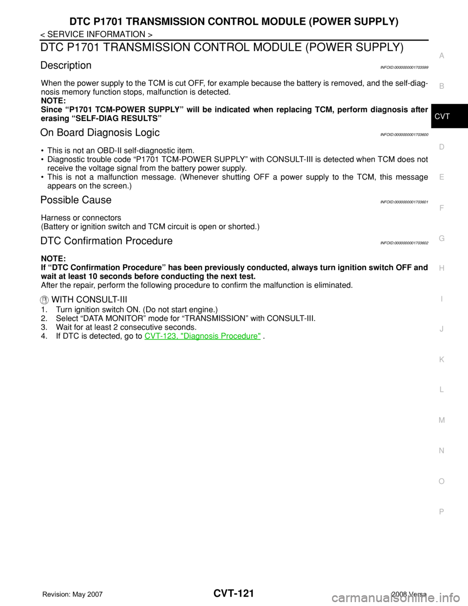
DescriptionINFOID:0000000001703599
When the power supply to the TCM is cut OFF, for example because the battery is removed, and the self-diag-
nosis memory function stops, malfunction is detected.
NOTE:
Since “P1701 TCM-POWER SUPPLY” will be indicated when replacing TCM, perform diagnosis after
erasing “SELF-DIAG RESULTS”
On Board Diagnosis LogicINFOID:0000000001703600
• This is not an OBD-II self-diagnostic item.
• Diagnostic trouble code “P1701 TCM-POWER SUPPLY” with CONSULT-III is detected when TCM does not
receive the voltage signal from the battery power supply.
• This is not a malfunction message. (Whenever shutting OFF a power supply to the TCM, this message
appears on the screen.)
Possible CauseINFOID:0000000001703601
Harness or connectors
(Battery or ignition switch and TCM circuit is open or shorted.)
DTC Confirmation ProcedureINFOID:0000000001703602
NOTE:
If “DTC Confirmation Procedure” has been previously conducted, always turn ignition switch OFF and
wait at least 10 seconds before conducting the next test.
After the repair, perform the following procedure to confirm the malfunction is eliminated.
WITH CONSULT-III
1. Turn ignition switch ON. (Do not start engine.)
2. Select “DATA MONITOR” mode for “TRANSMISSION” with CONSULT-III.
3. Wait for at least 2 consecutive seconds.
4. If DTC is detected, go to CVT-123, "
Diagnosis Procedure" .
Page 962 of 2771
DTC P1701 TRANSMISSION CONTROL MODULE (POWER SUPPLY)
CVT-123
< SERVICE INFORMATION >
D
E
F
G
H
I
J
K
L
MA
B
CVT
N
O
P
Diagnosis ProcedureINFOID:0000000001703604
1.CHECK DTC
1. Turn ignition switch ON. (Do not start engine.)
2. Select “SELF-DIAG RESULTS” mode for “TRANSMISSION” with CONSULT-III.
3. Erase self-diagnostic results. Refer to CVT-26, "
OBD-II Diagnostic Trouble Code (DTC)" .
4. Turn ignition switch OFF, and wait for 5 seconds or more.
5. Start engine.
6. Confirm self-diagnostic results again. Refer to CVT-47, "
CONSULT-III Function (TRANSMISSION)" .
Is the
“P1701 TCM-POWER SUPPLY” displayed?
YES >> GO TO 2.
NO >>INSPECTION END
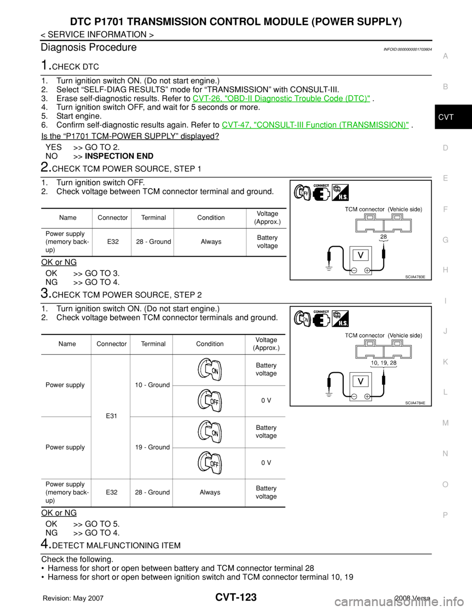
2.CHECK TCM POWER SOURCE, STEP 1
1. Turn ignition switch OFF.
2. Check voltage between TCM connector terminal and ground.
OK or NG
OK >> GO TO 3.
NG >> GO TO 4.
3.CHECK TCM POWER SOURCE, STEP 2
1. Turn ignition switch ON. (Do not start engine.)
2. Check voltage between TCM connector terminals and ground.
OK or NG
OK >> GO TO 5.
NG >> GO TO 4.
4.DETECT MALFUNCTIONING ITEM
Check the following.
• Harness for short or open between battery and TCM connector terminal 28
• Harness for short or open between ignition switch and TCM connector terminal 10, 19
Name Connector Terminal ConditionVoltage
(Approx.)
Power supply
(memory back-
up)E32 28 - Ground AlwaysBattery
voltage
SCIA4783E
Name Connector Terminal ConditionVoltage
(Approx.)
Power supply
E3110 - GroundBattery
voltage
0 V
Power supply 19 - GroundBattery
voltage
0 V
Power supply
(memory back-
up)E32 28 - Ground AlwaysBattery
voltage
SCIA4784E
Page 973 of 2771
CVT-134
< SERVICE INFORMATION >
DTC P1740 LOCK-UP SELECT SOLENOID VALVE CIRCUIT
Diagnosis Procedure
INFOID:0000000001703633
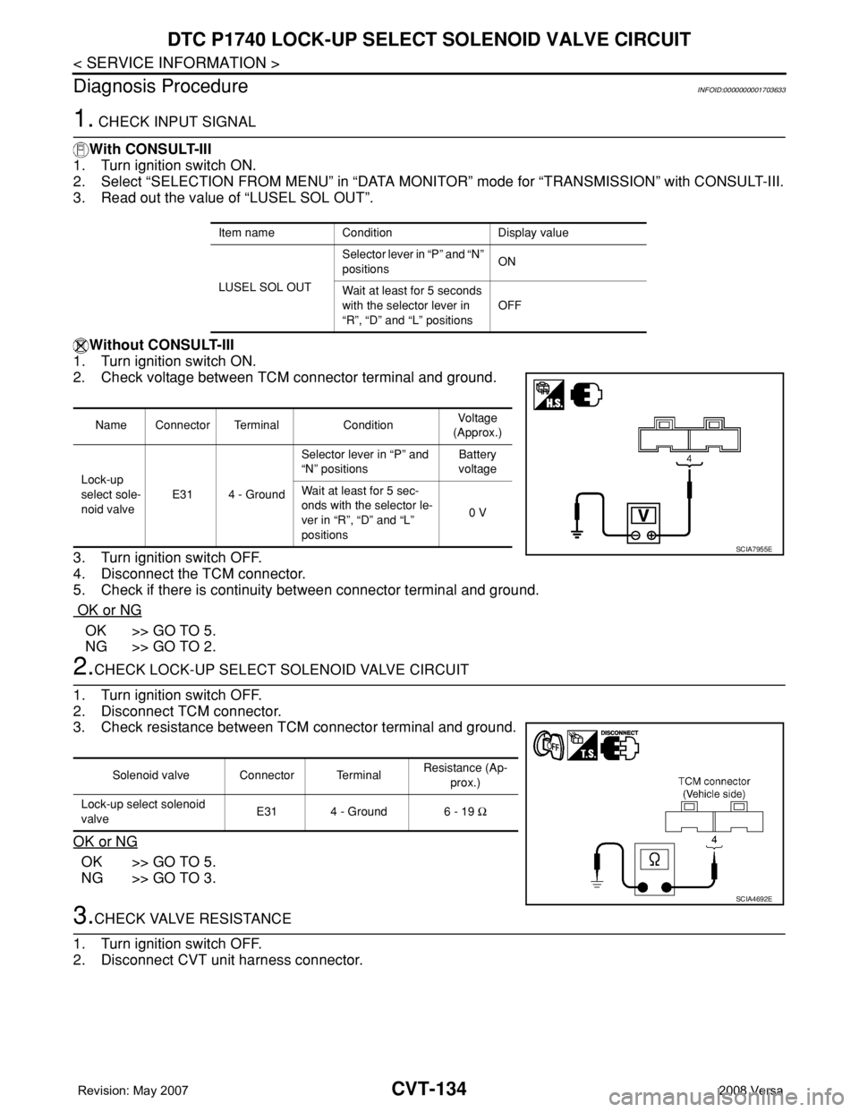
1. CHECK INPUT SIGNAL
With CONSULT-III
1. Turn ignition switch ON.
2. Select “SELECTION FROM MENU” in “DATA MONITOR” mode for “TRANSMISSION” with CONSULT-III.
3. Read out the value of “LUSEL SOL OUT”.
Without CONSULT-III
1. Turn ignition switch ON.
2. Check voltage between TCM connector terminal and ground.
3. Turn ignition switch OFF.
4. Disconnect the TCM connector.
5. Check if there is continuity between connector terminal and ground.
OK or NG
OK >> GO TO 5.
NG >> GO TO 2.
2.CHECK LOCK-UP SELECT SOLENOID VALVE CIRCUIT
1. Turn ignition switch OFF.
2. Disconnect TCM connector.
3. Check resistance between TCM connector terminal and ground.
OK or NG
OK >> GO TO 5.
NG >> GO TO 3.
3.CHECK VALVE RESISTANCE
1. Turn ignition switch OFF.
2. Disconnect CVT unit harness connector.
Item name Condition Display value
LUSEL SOL OUTSelector lever in “P” and “N”
positions ON
Wait at least for 5 seconds
with the selector lever in
“R”, “D” and “L” positionsOFF
Name Connector Terminal ConditionVoltage
(Approx.)
Lock-up
select sole-
noid valveE31 4 - GroundSelector lever in “P” and
“N” positions Battery
voltage
Wait at least for 5 sec-
onds with the selector le-
ver in “R”, “D” and “L”
positions0 V
SCIA7955E
Solenoid valve Connector TerminalResistance (Ap-
prox.)
Lock-up select solenoid
valveE31 4 - Ground 6 - 19 Ω
SCIA4692E
Page 991 of 2771

CVT-152
< SERVICE INFORMATION >
TROUBLE DIAGNOSIS FOR SYMPTOMS
O/D OFF indicator lamp does not come on for about 2 seconds when turning ignition switch ON.
DIAGNOSTIC PROCEDURE
1.CHECK CAN COMMUNICATION LINE
Perform the self-diagnosis check. Refer to CVT-47, "
CONSULT-III Function (TRANSMISSION)".
Is any malfunction of the
“U1000 CAN COMM CIRCUIT” indicated in the results?
YES >> Check CAN communication line. Refer to CVT-56.
NO >> GO TO 2.
2.CHECK TCM POWER SOURCE
1. Turn ignition switch ON.
2. Check voltage between TCM connector terminals and ground.
Refer to CVT-122, "
Wiring Diagram - CVT - POWER".
OK or NG
OK >> GO TO 4.
NG >> GO TO 3.
3.DETECT MALFUNCTIONING ITEM
Check the following.
• Harness for short or open between ignition switch and TCM connector terminal 10, 19
Refer to CVT-122, "
Wiring Diagram - CVT - POWER".
• 10 A fuse (No.49, located in the IPDM E/R). Refer to CVT-122, "
Wiring Diagram - CVT - POWER".
• Ignition switch. Refer to PG-3
.
OK or NG
OK >> GO TO 4.
NG >> Repair or replace damaged parts.
4.CHECK TCM GROUND CIRCUIT
1. Turn ignition switch OFF.
2. Disconnect TCM connector.
3. Check continuity between TCM connector terminals and ground.
Refer to CVT-122, "
Wiring Diagram - CVT - POWER".
OK or NG
OK >> GO TO 5.
NG >> Repair open circuit or short to ground or short to power
in harness or connectors.
5.DETECT MALFUNCTIONING ITEM
Check the following.
• Harness and fuse for short or open between ignition switch and O/D OFF indicator lamp
Refer to PG-3
.
OK or NG
OK >> GO TO 6.
NG >> Repair or replace damaged parts.
6.CHECK SYMPTOM
NameConnec-
torTerminal Voltage (Approx.)
Power supply E3110 Battery voltage
19 Battery voltage
SCIA4737E
NameConnec-
torTerminal Continuity
Ground E3225
Ye s
48
SCIA2671E