2008 NISSAN LATIO service
[x] Cancel search: servicePage 175 of 2771
CONTROL UNIT (RAM), CONTROL UNIT (ROM)
AT-163
< SERVICE INFORMATION >
D
E
F
G
H
I
J
K
L
MA
B
AT
N
O
P
CONTROL UNIT (RAM), CONTROL UNIT (ROM)
DescriptionINFOID:0000000001703320
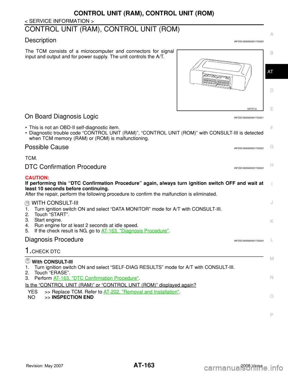
The TCM consists of a microcomputer and connectors for signal
input and output and for power supply. The unit controls the A/T.
On Board Diagnosis LogicINFOID:0000000001703321
• This is not an OBD-II self-diagnostic item.
• Diagnostic trouble code “CONTROL UNIT (RAM)”, “CONTROL UNIT (ROM)” with CONSULT-III is detected
when TCM memory (RAM) or (ROM) is malfunctioning.
Possible CauseINFOID:0000000001703322
TCM.
DTC Confirmation ProcedureINFOID:0000000001703323
CAUTION:
If performing this “DTC Confirmation Procedure” again, always turn ignition switch OFF and wait at
least 10 seconds before continuing.
After the repair, perform the following procedure to confirm the malfunction is eliminated.
WITH CONSULT-III
1. Turn ignition switch ON and select “DATA MONITOR” mode for A/T with CONSULT-III.
2. Touch “START”.
3. Start engine.
4. Run engine for at least 2 seconds at idle speed.
5. If the check result is NG, go to AT-163, "
Diagnosis Procedure".
Diagnosis ProcedureINFOID:0000000001703324
1.CHECK DTC
With CONSULT-III
1. Turn ignition switch ON and select “SELF-DIAG RESULTS” mode for A/T with CONSULT-III.
2. Touch “ERASE”.
3. Perform AT-163, "
DTC Confirmation Procedure".
Is the
“CONTROL UNIT (RAM)” or “CONTROL UNIT (ROM)” displayed again?
YES >> Replace TCM. Refer to AT-202, "Removal and Installation".
NO >>INSPECTION END
SAT574J
Page 176 of 2771
AT-164
< SERVICE INFORMATION >
MAIN POWER SUPPLY AND GROUND CIRCUIT
MAIN POWER SUPPLY AND GROUND CIRCUIT
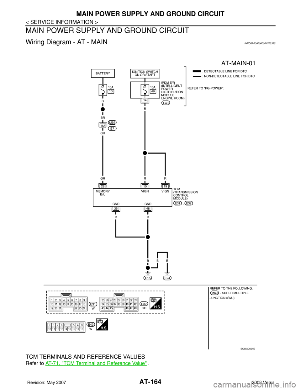
Wiring Diagram - AT - MAININFOID:0000000001703325
TCM TERMINALS AND REFERENCE VALUES
Refer to AT-71, "TCM Terminal and Reference Value" .
BCWA0661E
Page 177 of 2771
MAIN POWER SUPPLY AND GROUND CIRCUIT
AT-165
< SERVICE INFORMATION >
D
E
F
G
H
I
J
K
L
MA
B
AT
N
O
P
Diagnosis ProcedureINFOID:0000000001703326
1.CHECK TCM POWER SOURCE
1. Turn ignition switch ON. (Do not start engine.)
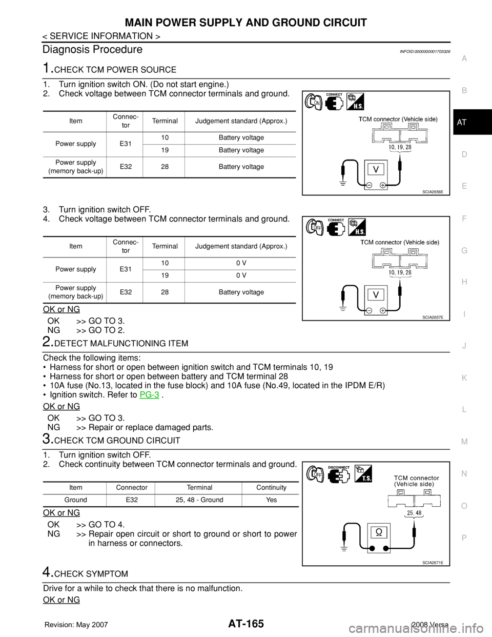
2. Check voltage between TCM connector terminals and ground.
3. Turn ignition switch OFF.
4. Check voltage between TCM connector terminals and ground.
OK or NG
OK >> GO TO 3.
NG >> GO TO 2.
2.DETECT MALFUNCTIONING ITEM
Check the following items:
• Harness for short or open between ignition switch and TCM terminals 10, 19
• Harness for short or open between battery and TCM terminal 28
• 10A fuse (No.13, located in the fuse block) and 10A fuse (No.49, located in the IPDM E/R)
• Ignition switch. Refer to PG-3
.
OK or NG
OK >> GO TO 3.
NG >> Repair or replace damaged parts.
3.CHECK TCM GROUND CIRCUIT
1. Turn ignition switch OFF.
2. Check continuity between TCM connector terminals and ground.
OK or NG
OK >> GO TO 4.
NG >> Repair open circuit or short to ground or short to power
in harness or connectors.
4.CHECK SYMPTOM
Drive for a while to check that there is no malfunction.
OK or NG
ItemConnec-
torTerminal Judgement standard (Approx.)
Power supply E3110 Battery voltage
19 Battery voltage
Power supply
(memory back-up)E32 28 Battery voltage
SCIA2656E
ItemConnec-
torTerminal Judgement standard (Approx.)
Power supply E3110 0 V
19 0 V
Power supply
(memory back-up)E32 28 Battery voltage
SCIA2657E
Item Connector Terminal Continuity
Ground E32 25, 48 - Ground Yes
SCIA2671E
Page 178 of 2771

AT-166
< SERVICE INFORMATION >
MAIN POWER SUPPLY AND GROUND CIRCUIT
OK >>INSPECTION END
NG >> GO TO 5.
5.CHECK TCM
1. Check TCM input/output signal. Refer to AT-71, "
TCM Terminal and Reference Value" .
2. If NG, recheck TCM pin terminals for damage or loose connection with harness connector.
OK or NG
OK >>INSPECTION END
NG >> Repair or replace damaged parts.
Page 179 of 2771
PNP, OD SWITCH AND CLOSED THROTTLE, WIDE OPEN THROTTLE POSI-
TION SIGNAL CIRCUIT
AT-167
< SERVICE INFORMATION >
D
E
F
G
H
I
J
K
L
MA
B
AT
N
O
P
PNP, OD SWITCH AND CLOSED THROTTLE, WIDE OPEN THROTTLE PO-
SITION SIGNAL CIRCUIT
CONSULT-III Reference Value in Data Monitor ModeINFOID:0000000001703327
TCM Terminal and Reference ValueINFOID:0000000001703328
TCM terminal data are reference values, measured between each terminal and ground.
Diagnosis ProcedureINFOID:0000000001703329
1.CHECK CAN COMMUNICATION LINE
Perform self-diagnosis. Refer to AT-73, "
CONSULT-III Function (A/T)".
Is a malfunction in the CAN communication indicated in the results?
YES >> Check CAN communication line. Refer to AT- 8 3.
NO (With CONSULT-III) >>GO TO 2.
NO (Without CONSULT-III) >>GO TO 3.
Item name Condition Display value
PN POSI SWWhen setting selector lever to “N” or “P” position. ON
When setting selector lever to other positions. OFF
R POSITION SWWhen setting selector lever to “R” position. ON
When setting selector lever to other positions. OFF
D POSITION SWWhen setting selector lever to “D” position. ON
When setting selector lever to other positions. OFF
2 POSITION SWWhen setting selector lever to “2” position. ON
When setting selector lever to other positions. OFF
1 POSITION SWWhen setting selector lever to “1” position. ON
When setting selector lever to other positions. OFF
OVERDRIVE SWWhen overdrive control switch is depressed. ON
When overdrive control switch is released. OFF
CLOSED THL/SWReleased accelerator pedal. ON
Depressed accelerator pedal. OFF
W/O THRL/P-SWFully depressed accelerator pedal. ON
Released accelerator pedal. OFF
Terminal Wire color Item ConditionJudgement standard
(Approx.)
26 YPNP switch “1” posi-
tion
andWhen setting selector lever to “1” position. Battery voltage
When setting selector lever to other positions. 0 V
27 GPNP switch “2” posi-
tionWhen setting selector lever to “2” position. Battery voltage
When setting selector lever to other positions. 0 V
34 LGPNP switch “D” posi-
tionWhen setting selector lever to “D” position. Battery voltage
When setting selector lever to other positions. 0 V
35 SBPNP switch “R” posi-
tionWhen setting selector lever to “R” position. Battery voltage
When setting selector lever to other positions. 0 V
36 RPNP switch “N” or “P”
positionWhen setting selector lever to “N” or “P” posi-
tions.Battery voltage
When setting selector lever to other positions. 0 V
Page 180 of 2771
AT-168
< SERVICE INFORMATION >
PNP, OD SWITCH AND CLOSED THROTTLE, WIDE OPEN THROTTLE POSI-
TION SIGNAL CIRCUIT
2.CHECK PNP SWITCH CIRCUIT
With CONSULT-III
1. Turn ignition switch ON. (Do not start engine.)
2. Select “TCM INPUT SIGNALS” in “DATA MONITOR” mode for “A/T” with CONSULT-III.
3. Read out “P·N”, “R”, “D”, “2” and “1” position switches moving selector lever to each position.
OK or NG
OK >> GO TO 4.
NG >> Check PNP switch circuit. Refer to AT- 8 6
.
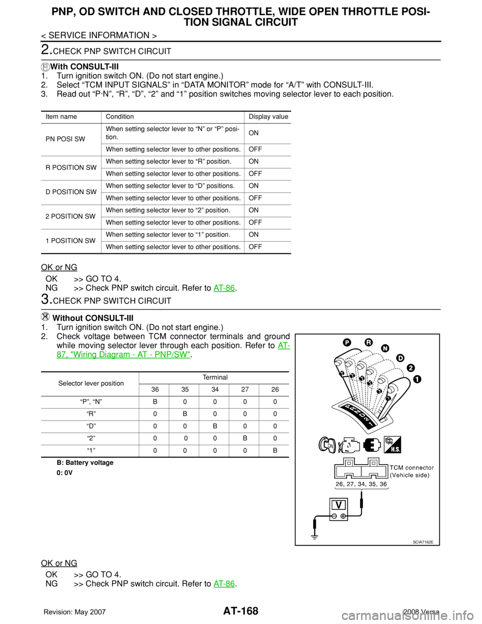
3.CHECK PNP SWITCH CIRCUIT
Without CONSULT-III
1. Turn ignition switch ON. (Do not start engine.)
2. Check voltage between TCM connector terminals and ground
while moving selector lever through each position. Refer to AT-
87, "Wiring Diagram - AT - PNP/SW".
B: Battery voltage
0: 0V
OK or NG
OK >> GO TO 4.
NG >> Check PNP switch circuit. Refer to AT- 8 6
.
Item name Condition Display value
PN POSI SWWhen setting selector lever to “N” or “P” posi-
tion.ON
When setting selector lever to other positions. OFF
R POSITION SWWhen setting selector lever to “R” position. ON
When setting selector lever to other positions. OFF
D POSITION SWWhen setting selector lever to “D” positions. ON
When setting selector lever to other positions. OFF
2 POSITION SWWhen setting selector lever to “2” position. ON
When setting selector lever to other positions. OFF
1 POSITION SWWhen setting selector lever to “1” position. ON
When setting selector lever to other positions. OFF
Selector lever positionTe r m i n a l
36 35 34 27 26
“P”, “N” B0000
“R” 0B000
“D” 0 0 B 0 0
“2” 0 0 0 B 0
“1” 0000B
SCIA7162E
Page 181 of 2771
PNP, OD SWITCH AND CLOSED THROTTLE, WIDE OPEN THROTTLE POSI-
TION SIGNAL CIRCUIT
AT-169
< SERVICE INFORMATION >
D
E
F
G
H
I
J
K
L
MA
B
AT
N
O
P
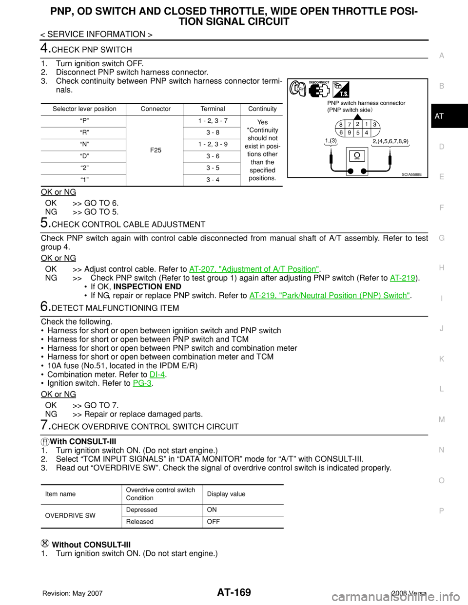
4.CHECK PNP SWITCH
1. Turn ignition switch OFF.
2. Disconnect PNP switch harness connector.
3. Check continuity between PNP switch harness connector termi-
nals.
OK or NG
OK >> GO TO 6.
NG >> GO TO 5.
5.CHECK CONTROL CABLE ADJUSTMENT
Check PNP switch again with control cable disconnected from manual shaft of A/T assembly. Refer to test
group 4.
OK or NG
OK >> Adjust control cable. Refer to AT-207, "Adjustment of A/T Position".
NG >> Check PNP switch (Refer to test group 1) again after adjusting PNP switch (Refer to AT-219
).
• If OK, INSPECTION END
• If NG, repair or replace PNP switch. Refer to AT-219, "
Park/Neutral Position (PNP) Switch".
6.DETECT MALFUNCTIONING ITEM
Check the following.
• Harness for short or open between ignition switch and PNP switch
• Harness for short or open between PNP switch and TCM
• Harness for short or open between PNP switch and combination meter
• Harness for short or open between combination meter and TCM
• 10A fuse (No.51, located in the IPDM E/R)
• Combination meter. Refer to DI-4
.
• Ignition switch. Refer to PG-3
.
OK or NG
OK >> GO TO 7.
NG >> Repair or replace damaged parts.
7.CHECK OVERDRIVE CONTROL SWITCH CIRCUIT
With CONSULT-III
1. Turn ignition switch ON. (Do not start engine.)
2. Select “TCM INPUT SIGNALS” in “DATA MONITOR” mode for “A/T” with CONSULT-III.
3. Read out “OVERDRIVE SW”. Check the signal of overdrive control switch is indicated properly.
Without CONSULT-III
1. Turn ignition switch ON. (Do not start engine.)
Selector lever position Connector Terminal Continuity
“P”
F251 - 2, 3 - 7
Ye s
*Continuity
should not
exist in posi-
tions other
than the
specified
positions. “R” 3 - 8
“N” 1 - 2, 3 - 9
“D” 3 - 6
“2” 3 - 5
“1” 3 - 4
SCIA5588E
Item nameOverdrive control switch
ConditionDisplay value
OVERDRIVE SWDepressed ON
Released OFF
Page 182 of 2771
AT-170
< SERVICE INFORMATION >
PNP, OD SWITCH AND CLOSED THROTTLE, WIDE OPEN THROTTLE POSI-
TION SIGNAL CIRCUIT
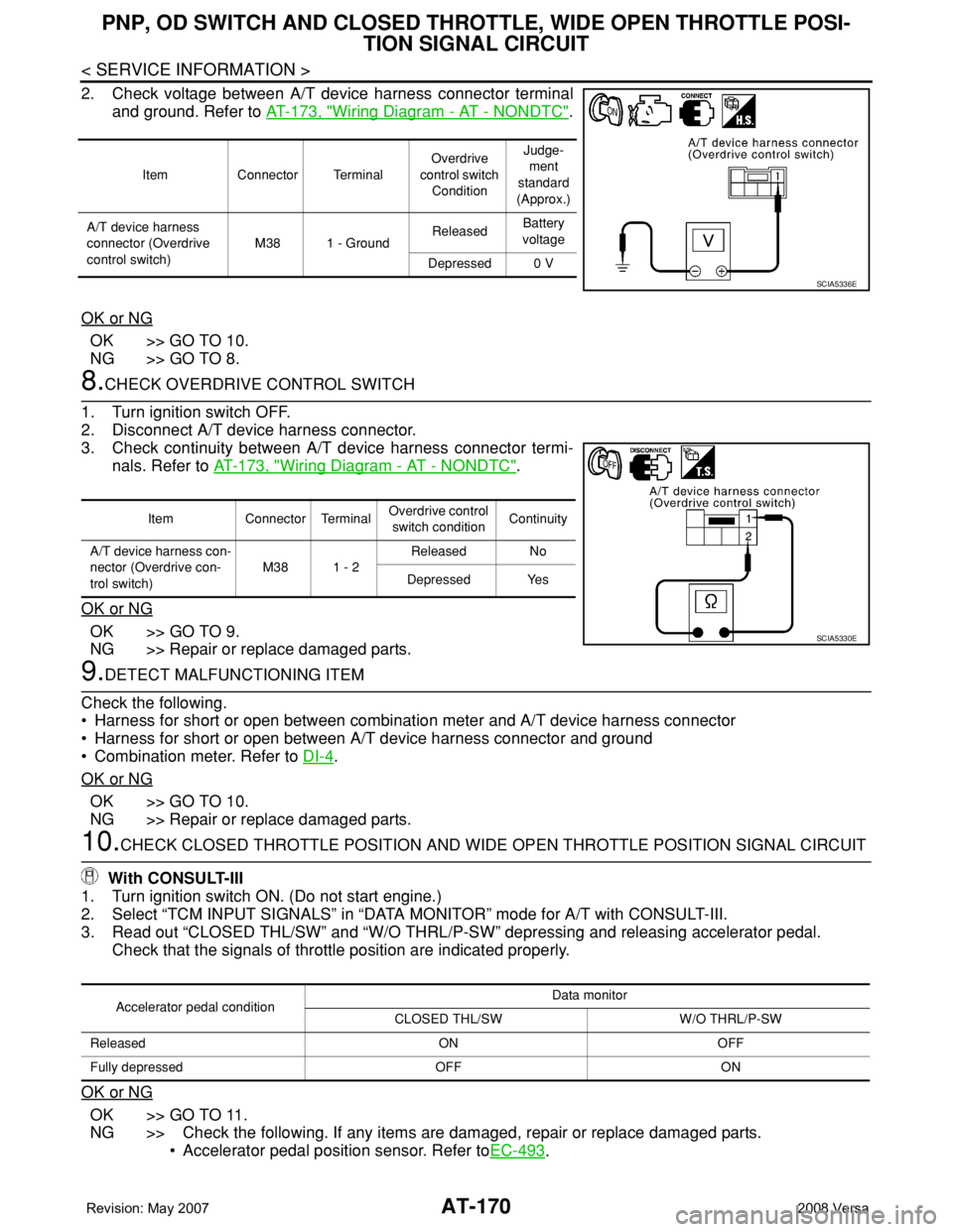
2. Check voltage between A/T device harness connector terminal
and ground. Refer to AT-173, "
Wiring Diagram - AT - NONDTC".
OK or NG
OK >> GO TO 10.
NG >> GO TO 8.
8.CHECK OVERDRIVE CONTROL SWITCH
1. Turn ignition switch OFF.
2. Disconnect A/T device harness connector.
3. Check continuity between A/T device harness connector termi-
nals. Refer to AT-173, "
Wiring Diagram - AT - NONDTC".
OK or NG
OK >> GO TO 9.
NG >> Repair or replace damaged parts.
9.DETECT MALFUNCTIONING ITEM
Check the following.
• Harness for short or open between combination meter and A/T device harness connector
• Harness for short or open between A/T device harness connector and ground
• Combination meter. Refer to DI-4
.
OK or NG
OK >> GO TO 10.
NG >> Repair or replace damaged parts.
10.CHECK CLOSED THROTTLE POSITION AND WIDE OPEN THROTTLE POSITION SIGNAL CIRCUIT
With CONSULT-III
1. Turn ignition switch ON. (Do not start engine.)
2. Select “TCM INPUT SIGNALS” in “DATA MONITOR” mode for A/T with CONSULT-III.
3. Read out “CLOSED THL/SW” and “W/O THRL/P-SW” depressing and releasing accelerator pedal.
Check that the signals of throttle position are indicated properly.
OK or NG
OK >> GO TO 11.
NG >> Check the following. If any items are damaged, repair or replace damaged parts.
• Accelerator pedal position sensor. Refer toEC-493
.
Item Connector TerminalOverdrive
control switch
ConditionJudge-
ment
standard
(Approx.)
A/T device harness
connector (Overdrive
control switch)M38 1 - GroundReleasedBattery
voltage
Depressed 0 V
SCIA5336E
Item Connector TerminalOverdrive control
switch conditionContinuity
A/T device harness con-
nector (Overdrive con-
trol switch)M38 1 - 2Released No
Depressed Yes
SCIA5330E
Accelerator pedal conditionData monitor
CLOSED THL/SW W/O THRL/P-SW
Released ON OFF
Fully depressed OFF ON