Page 2395 of 2771
THERMO CONTROL AMPLIFIER
MTC-57
< SERVICE INFORMATION >
C
D
E
F
G
H
I
K
L
MA
B
MTC
N
O
P
THERMO CONTROL AMPLIFIER
Removal and InstallationINFOID:0000000001704311
NOTE:
Only TYPE 1 systems are equipped with a thermo control amplifier.
REMOVAL
1. Remove evaporator. Refer to MTC-83, "Removal and Installation of Evaporator" .
CAUTION:
Cap or wrap the joint of the pipe with suitable material such as vinyl tape to avoid the entry of air.
2. Remove thermo control amp. (1) from evaporator (2).
INSTALLATION
Installation is in the reverse order of removal.
CAUTION:
• Replace O-rings for A/C piping with new ones, and apply compressor oil when installing.
• Mark the mounting position of thermo control amp.
• When recharging refrigerant, check for leaks.
ZJIA0798J
Page 2397 of 2771

A/C UNIT ASSEMBLY
MTC-59
< SERVICE INFORMATION >
C
D
E
F
G
H
I
K
L
MA
B
MTC
N
O
P
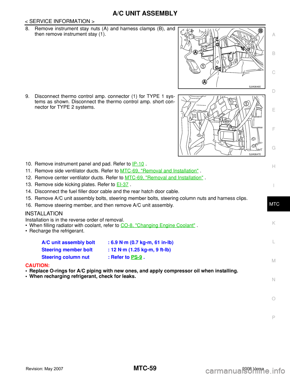
8. Remove instrument stay nuts (A) and harness clamps (B), and
then remove instrument stay (1).
9. Disconnect thermo control amp. connector (1) for TYPE 1 sys-
tems as shown. Disconnect the thermo control amp. short con-
nector for TYPE 2 systems.
10. Remove instrument panel and pad. Refer to IP-10
.
11. Remove side ventilator ducts. Refer to MTC-69, "
Removal and Installation" .
12. Remove center ventilator ducts. Refer to MTC-69, "
Removal and Installation" .
13. Remove side kicking plates. Refer to EI-37
.
14. Disconnect the fuel filler door cable and the rear hatch door cable.
15. Remove A/C unit assembly bolts, steering member bolts, steering column nuts and harness clips.
16. Remove steering member, and then remove A/C unit assembly.
INSTALLATION
Installation is in the reverse order of removal.
• When filling radiator with coolant, refer to CO-8, "
Changing Engine Coolant" .
• Recharge the refrigerant.
CAUTION:
• Replace O-rings for A/C piping with new ones, and apply compressor oil when installing.
• When recharging refrigerant, check for leaks.
SJIA0646E
SJIA0647E
A/C unit assembly bolt : 6.9 N·m (0.7 kg-m, 61 in-lb)
Steering member bolt : 12 N·m (1.25 kg-m, 9 ft-lb)
Steering column nut : Refer to PS-9
.
Page 2414 of 2771
MTC-76
< SERVICE INFORMATION >
REFRIGERANT LINES
Component
INFOID:0000000001704323
Type 1 A/C System
WJIA2200E
1. Evaporator 2. Expansion valve 3. Low-pressure service valve
4. High-pressure service valve 5. Refrigerant pressure sensor 6. Shaft seal
7. Drain hose
Page 2415 of 2771
REFRIGERANT LINES
MTC-77
< SERVICE INFORMATION >
C
D
E
F
G
H
I
K
L
MA
B
MTC
N
O
P
Type 2 A/C System
WJIA2202E
1. Evaporator 2. Expansion valve 3. Low-pressure service valve
4. High-pressure service valve 5. Refrigerant pressure sensor 6. Shaft seal
7. Drain hose
Page 2416 of 2771
MTC-78
< SERVICE INFORMATION >
REFRIGERANT LINES
Idler Pulley - Without A/C
Refer to MTC-4, "Precaution for Refrigerant Connection".
Removal and Installation of CompressorINFOID:0000000001704324
REMOVAL
1. Use the recovery/recycling equipment to evacuate the refrigerant.
2. Remove the two engine undercovers, using power tools.
3. Remove low-pressure flexible hose nut (A) and high-pressure
flexible hose bolt (B) from compressor.
CAUTION:
Cap or wrap the joint of the pipe with suitable material such
as vinyl tape to avoid the entry of air.
NOTE:
Type 1 shown, type 2 is similar.
4. Remove A/C compressor belt. Refer to EM-13
.
5. Disconnect compressor connector (C).
6. Remove bolts (A) from compressor (1), using power tools.
7. Remove compressor (1) downward from the engine compart-
ment.
WJIA2204E
1. Idler pulley 2. Bracket 3. Shaft
SJIA0671E
SJIA0672E
Page 2417 of 2771

REFRIGERANT LINES
MTC-79
< SERVICE INFORMATION >
C
D
E
F
G
H
I
K
L
MA
B
MTC
N
O
P
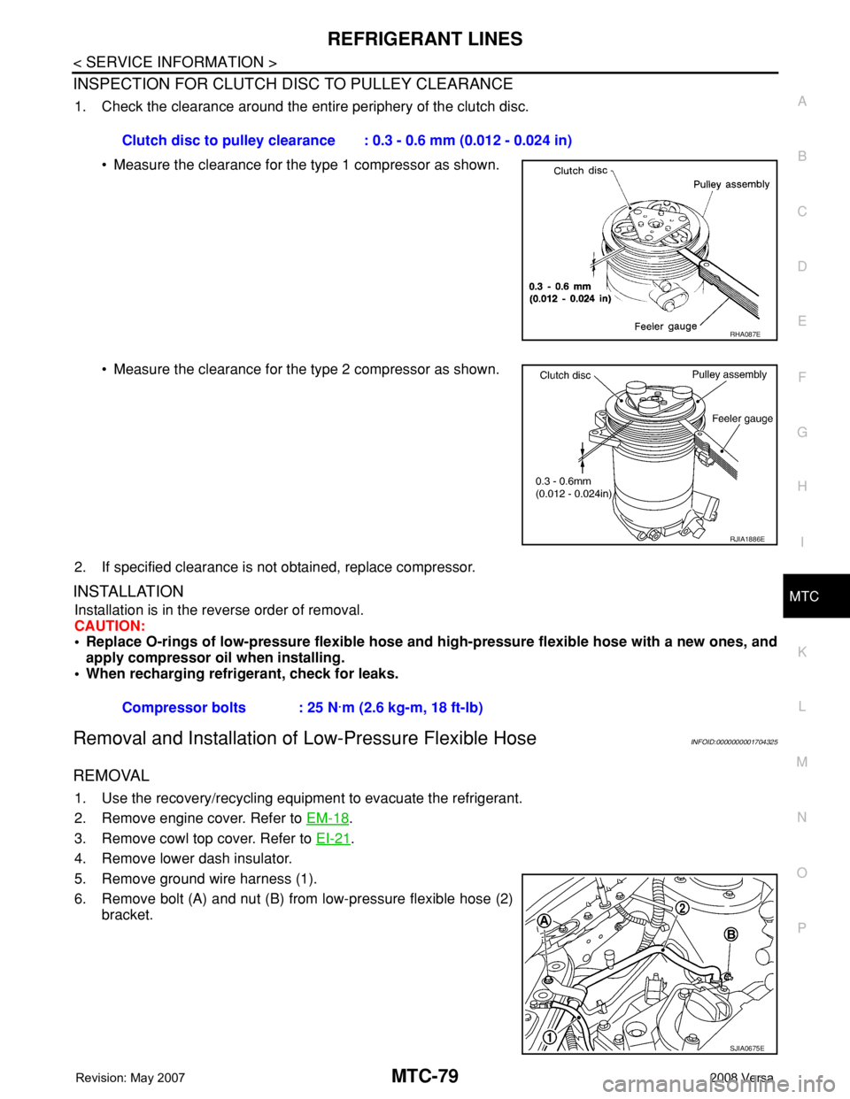
INSPECTION FOR CLUTCH DISC TO PULLEY CLEARANCE
1. Check the clearance around the entire periphery of the clutch disc.
• Measure the clearance for the type 1 compressor as shown.
• Measure the clearance for the type 2 compressor as shown.
2. If specified clearance is not obtained, replace compressor.
INSTALLATION
Installation is in the reverse order of removal.
CAUTION:
• Replace O-rings of low-pressure flexible hose and high-pressure flexible hose with a new ones, and
apply compressor oil when installing.
• When recharging refrigerant, check for leaks.
Removal and Installation of Low-Pressure Flexible HoseINFOID:0000000001704325
REMOVAL
1. Use the recovery/recycling equipment to evacuate the refrigerant.
2. Remove engine cover. Refer to EM-18
.
3. Remove cowl top cover. Refer to EI-21
.
4. Remove lower dash insulator.
5. Remove ground wire harness (1).
6. Remove bolt (A) and nut (B) from low-pressure flexible hose (2)
bracket.Clutch disc to pulley clearance : 0.3 - 0.6 mm (0.012 - 0.024 in)
RHA087E
RJIA1886E
Compressor bolts : 25 N·m (2.6 kg-m, 18 ft-lb)
SJIA0675E
Page 2422 of 2771

MTC-84
< SERVICE INFORMATION >
REFRIGERANT LINES
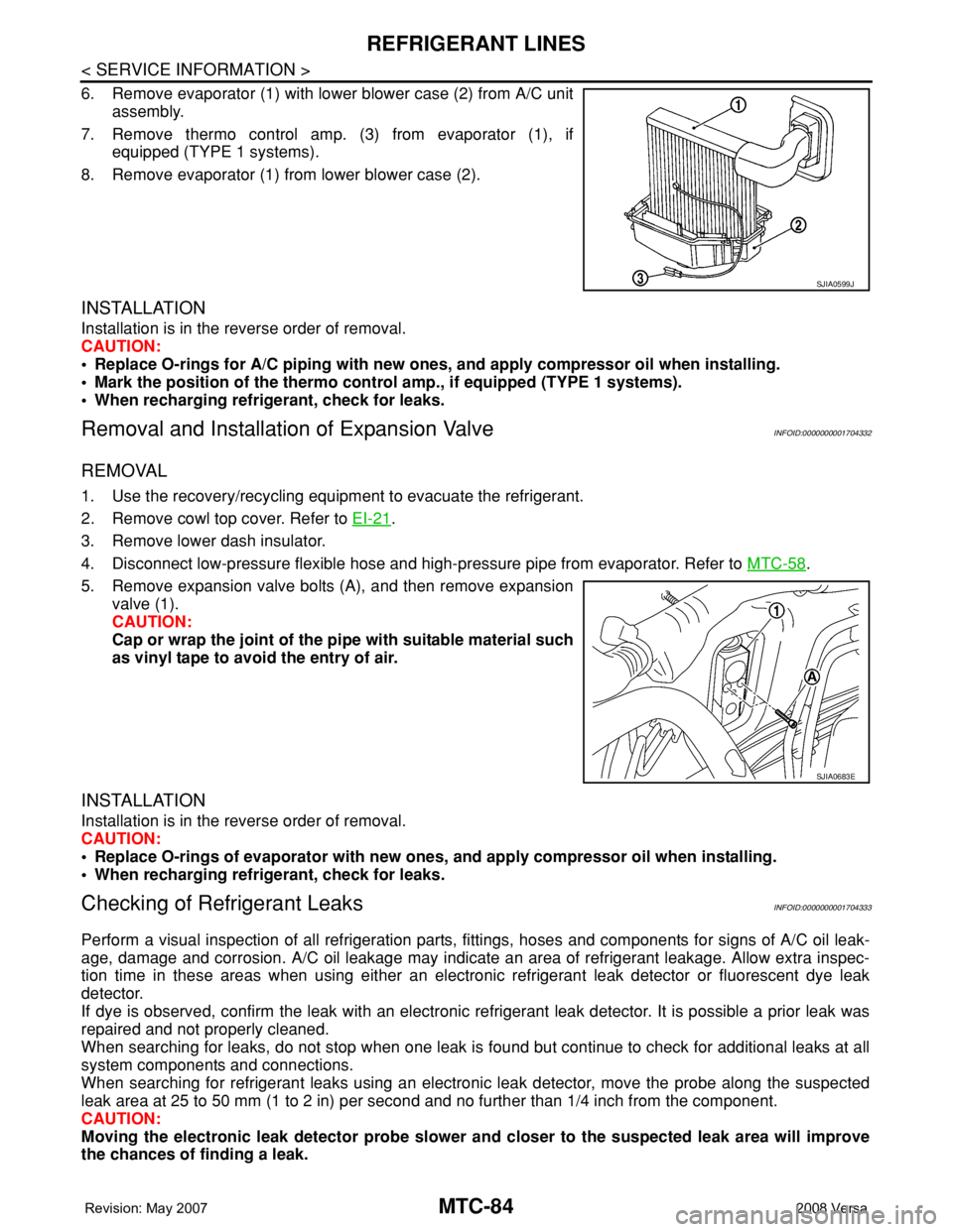
6. Remove evaporator (1) with lower blower case (2) from A/C unit
assembly.
7. Remove thermo control amp. (3) from evaporator (1), if
equipped (TYPE 1 systems).
8. Remove evaporator (1) from lower blower case (2).
INSTALLATION
Installation is in the reverse order of removal.
CAUTION:
• Replace O-rings for A/C piping with new ones, and apply compressor oil when installing.
• Mark the position of the thermo control amp., if equipped (TYPE 1 systems).
• When recharging refrigerant, check for leaks.
Removal and Installation of Expansion ValveINFOID:0000000001704332
REMOVAL
1. Use the recovery/recycling equipment to evacuate the refrigerant.
2. Remove cowl top cover. Refer to EI-21
.
3. Remove lower dash insulator.
4. Disconnect low-pressure flexible hose and high-pressure pipe from evaporator. Refer to MTC-58
.
5. Remove expansion valve bolts (A), and then remove expansion
valve (1).
CAUTION:
Cap or wrap the joint of the pipe with suitable material such
as vinyl tape to avoid the entry of air.
INSTALLATION
Installation is in the reverse order of removal.
CAUTION:
• Replace O-rings of evaporator with new ones, and apply compressor oil when installing.
• When recharging refrigerant, check for leaks.
Checking of Refrigerant LeaksINFOID:0000000001704333
Perform a visual inspection of all refrigeration parts, fittings, hoses and components for signs of A/C oil leak-
age, damage and corrosion. A/C oil leakage may indicate an area of refrigerant leakage. Allow extra inspec-
tion time in these areas when using either an electronic refrigerant leak detector or fluorescent dye leak
detector.
If dye is observed, confirm the leak with an electronic refrigerant leak detector. It is possible a prior leak was
repaired and not properly cleaned.
When searching for leaks, do not stop when one leak is found but continue to check for additional leaks at all
system components and connections.
When searching for refrigerant leaks using an electronic leak detector, move the probe along the suspected
leak area at 25 to 50 mm (1 to 2 in) per second and no further than 1/4 inch from the component.
CAUTION:
Moving the electronic leak detector probe slower and closer to the suspected leak area will improve
the chances of finding a leak.
SJIA0599J
SJIA0683E
Page 2426 of 2771

MTC-88
< SERVICE INFORMATION >
SERVICE DATA AND SPECIFICATIONS (SDS)
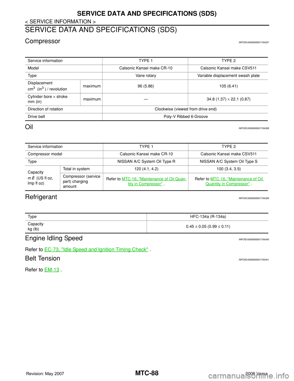
SERVICE DATA AND SPECIFICATIONS (SDS)
CompressorINFOID:0000000001704337
OilINFOID:0000000001704338
RefrigerantINFOID:0000000001704339
Engine Idling SpeedINFOID:0000000001704340
Refer to EC-73, "Idle Speed and Ignition Timing Check" .
Belt TensionINFOID:0000000001704341
Refer to EM-13 .
Service information TYPE 1 TYPE 2
Model Calsonic Kansei make CR-10 Calsonic Kansei make CSV511
Type Vane rotary Variable displacement swash plate
Displacement
cm
3 (in3 ) / revolutionmaximum 96 (5.86) 105 (6.41)
Cylinder bore × stroke
mm (in)maximum — 34.8 (1.37) × 22.1 (0.87)
Direction of rotation Clockwise (viewed from drive end)
Drive belt Poly-V Ribbed 6-Groove
Service information TYPE 1 TYPE 2
Compressor model Calsonic Kansei make CR-10 Calsonic Kansei make CSV511
Type NISSAN A/C System Oil Type R NISSAN A/C System Oil Type S
Capacity
m (US fl oz,
lmp fl oz)Total in system 120 (4.1, 4.2) 100 (3.4, 3.5)
Compressor (service
part) charging
amountRefer to MTC-16, "
Maintenance of Oil Quan-
tity in Compressor" .Refer to MTC-16, "
Maintenance of Oil
Quantity in Compressor" .
Ty p eHFC-134a (R-134a)
Capacity
kg (lb)0.45 ± 0.05 (0.99 ± 0.11)