2008 NISSAN LATIO air filter
[x] Cancel search: air filterPage 201 of 2771
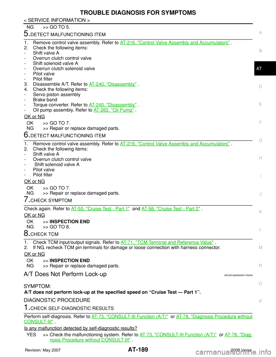
TROUBLE DIAGNOSIS FOR SYMPTOMS
AT-189
< SERVICE INFORMATION >
D
E
F
G
H
I
J
K
L
MA
B
AT
N
O
P
NG >> GO TO 5.
5.DETECT MALFUNCTIONING ITEM
1. Remove control valve assembly. Refer to AT-216, "
Control Valve Assembly and Accumulators" .
2. Check the following items:
- Shift valve A
- Overrun clutch control valve
- Shift solenoid valve A
- Overrun clutch solenoid valve
- Pilot valve
- Pilot filter
3. Disassemble A/T. Refer to AT-240, "
Disassembly" .
4. Check the following items:
- Servo piston assembly
- Brake band
- Torque converter. Refer to AT-240, "
Disassembly" .
- Oil pump assembly. Refer to AT-260, "
Oil Pump" .
OK or NG
OK >> GO TO 7.
NG >> Repair or replace damaged parts.
6.DETECT MALFUNCTIONING ITEM
1. Remove control valve assembly. Refer to AT-216, "
Control Valve Assembly and Accumulators" .
2. Check the following items:
- Shift valve A
- Overrun clutch control valve
- Shift solenoid valve A
- Pilot valve
- Pilot filter
OK or NG
OK >> GO TO 7.
NG >> Repair or replace damaged parts.
7.CHECK SYMPTOM
Check again. Refer to AT-55, "
Cruise Test - Part 1" and AT-58, "Cruise Test - Part 2" .
OK or NG
OK >>INSPECTION END
NG >> GO TO 8.
8.CHECK TCM
1. Check TCM input/output signals. Refer to AT-71, "
TCM Terminal and Reference Value" .
2. If NG, recheck TCM pin terminals for damage or loose connection with harness connector.
OK or NG
OK >>INSPECTION END
NG >> Repair or replace damaged parts.
A/T Does Not Perform Lock-upINFOID:0000000001703346
SYMPTOM:
A/T does not perform lock-up at the specified speed on “Cruise Test — Part 1”.
DIAGNOSTIC PROCEDURE
1.CHECK SELF-DIAGNOSTIC RESULTS
Perform self-diagnosis. Refer to AT-73, "
CONSULT-III Function (A/T)" or AT-78, "Diagnosis Procedure without
CONSULT-III" .
Is any malfunction detected by self-diagnostic results?
YES >> Check the malfunctioning system. Refer to AT-73, "CONSULT-III Function (A/T)" or AT-78, "Diag-
nosis Procedure without CONSULT-III" .
Page 202 of 2771
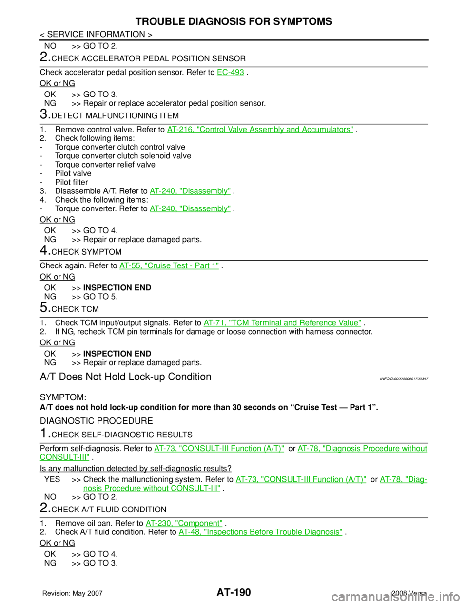
AT-190
< SERVICE INFORMATION >
TROUBLE DIAGNOSIS FOR SYMPTOMS
NO >> GO TO 2.
2.CHECK ACCELERATOR PEDAL POSITION SENSOR
Check accelerator pedal position sensor. Refer to EC-493
.
OK or NG
OK >> GO TO 3.
NG >> Repair or replace accelerator pedal position sensor.
3.DETECT MALFUNCTIONING ITEM
1. Remove control valve. Refer to AT-216, "
Control Valve Assembly and Accumulators" .
2. Check following items:
- Torque converter clutch control valve
- Torque converter clutch solenoid valve
- Torque converter relief valve
- Pilot valve
- Pilot filter
3. Disassemble A/T. Refer to AT-240, "
Disassembly" .
4. Check the following items:
- Torque converter. Refer to AT-240, "
Disassembly" .
OK or NG
OK >> GO TO 4.
NG >> Repair or replace damaged parts.
4.CHECK SYMPTOM
Check again. Refer to AT-55, "
Cruise Test - Part 1" .
OK or NG
OK >>INSPECTION END
NG >> GO TO 5.
5.CHECK TCM
1. Check TCM input/output signals. Refer to AT-71, "
TCM Terminal and Reference Value" .
2. If NG, recheck TCM pin terminals for damage or loose connection with harness connector.
OK or NG
OK >>INSPECTION END
NG >> Repair or replace damaged parts.
A/T Does Not Hold Lock-up ConditionINFOID:0000000001703347
SYMPTOM:
A/T does not hold lock-up condition for more than 30 seconds on “Cruise Test — Part 1”.
DIAGNOSTIC PROCEDURE
1.CHECK SELF-DIAGNOSTIC RESULTS
Perform self-diagnosis. Refer to AT-73, "
CONSULT-III Function (A/T)" or AT-78, "Diagnosis Procedure without
CONSULT-III" .
Is any malfunction detected by self-diagnostic results?
YES >> Check the malfunctioning system. Refer to AT-73, "CONSULT-III Function (A/T)" or AT-78, "Diag-
nosis Procedure without CONSULT-III" .
NO >> GO TO 2.
2.CHECK A/T FLUID CONDITION
1. Remove oil pan. Refer to AT-230, "
Component" .
2. Check A/T fluid condition. Refer to AT-48, "
Inspections Before Trouble Diagnosis" .
OK or NG
OK >> GO TO 4.
NG >> GO TO 3.
Page 203 of 2771
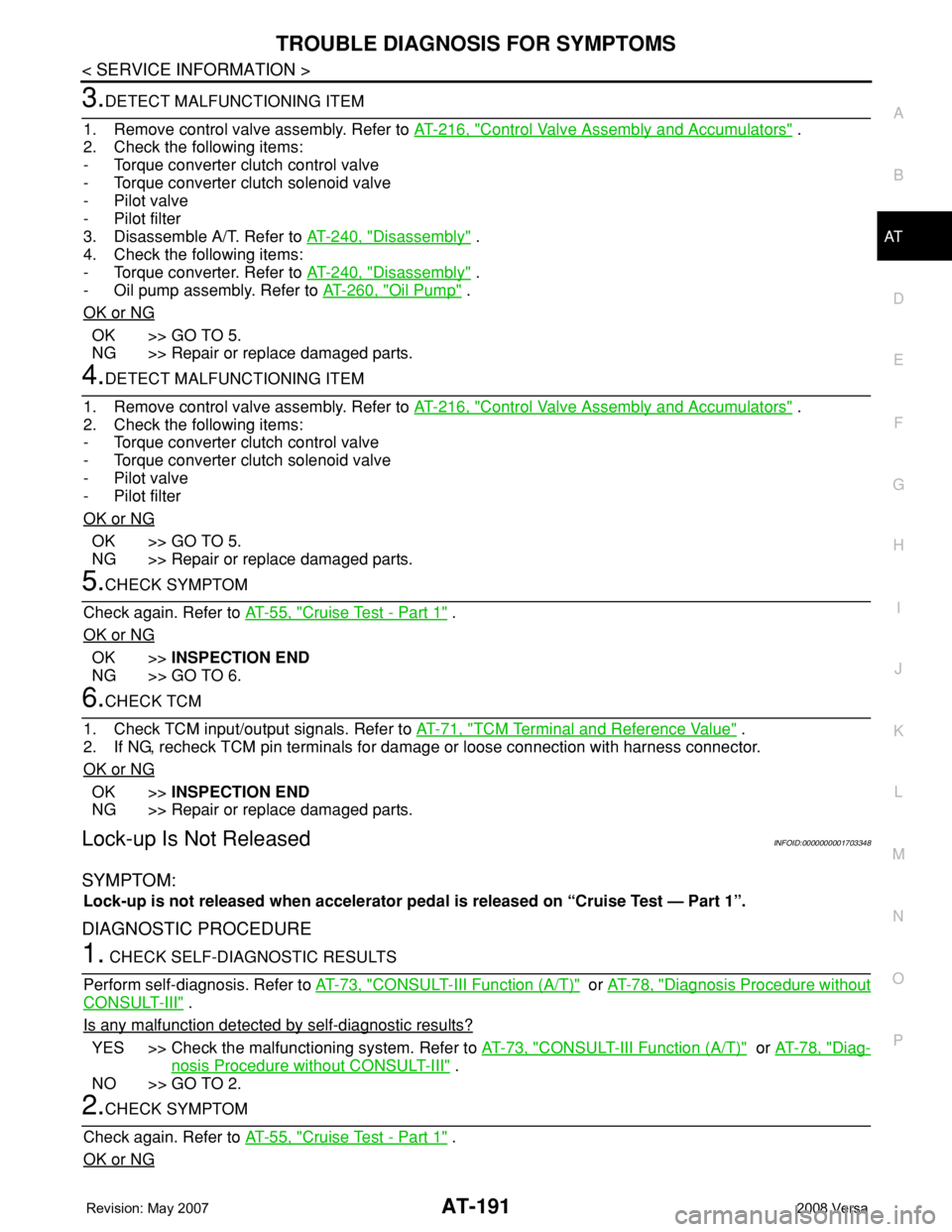
TROUBLE DIAGNOSIS FOR SYMPTOMS
AT-191
< SERVICE INFORMATION >
D
E
F
G
H
I
J
K
L
MA
B
AT
N
O
P
3.DETECT MALFUNCTIONING ITEM
1. Remove control valve assembly. Refer to AT-216, "
Control Valve Assembly and Accumulators" .
2. Check the following items:
- Torque converter clutch control valve
- Torque converter clutch solenoid valve
- Pilot valve
- Pilot filter
3. Disassemble A/T. Refer to AT-240, "
Disassembly" .
4. Check the following items:
- Torque converter. Refer to AT-240, "
Disassembly" .
- Oil pump assembly. Refer to AT-260, "
Oil Pump" .
OK or NG
OK >> GO TO 5.
NG >> Repair or replace damaged parts.
4.DETECT MALFUNCTIONING ITEM
1. Remove control valve assembly. Refer to AT-216, "
Control Valve Assembly and Accumulators" .
2. Check the following items:
- Torque converter clutch control valve
- Torque converter clutch solenoid valve
- Pilot valve
- Pilot filter
OK or NG
OK >> GO TO 5.
NG >> Repair or replace damaged parts.
5.CHECK SYMPTOM
Check again. Refer to AT-55, "
Cruise Test - Part 1" .
OK or NG
OK >>INSPECTION END
NG >> GO TO 6.
6.CHECK TCM
1. Check TCM input/output signals. Refer to AT-71, "
TCM Terminal and Reference Value" .
2. If NG, recheck TCM pin terminals for damage or loose connection with harness connector.
OK or NG
OK >>INSPECTION END
NG >> Repair or replace damaged parts.
Lock-up Is Not ReleasedINFOID:0000000001703348
SYMPTOM:
Lock-up is not released when accelerator pedal is released on “Cruise Test — Part 1”.
DIAGNOSTIC PROCEDURE
1. CHECK SELF-DIAGNOSTIC RESULTS
Perform self-diagnosis. Refer to AT-73, "
CONSULT-III Function (A/T)" or AT-78, "Diagnosis Procedure without
CONSULT-III" .
Is any malfunction detected by self-diagnostic results?
YES >> Check the malfunctioning system. Refer to AT-73, "CONSULT-III Function (A/T)" or AT-78, "Diag-
nosis Procedure without CONSULT-III" .
NO >> GO TO 2.
2.CHECK SYMPTOM
Check again. Refer to AT-55, "
Cruise Test - Part 1" .
OK or NG
Page 276 of 2771
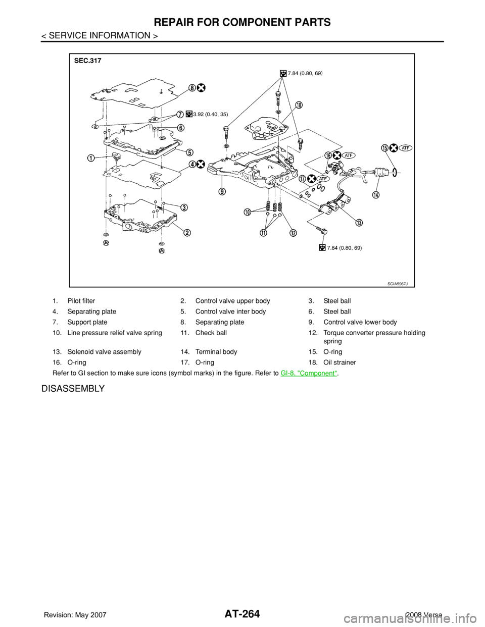
AT-264
< SERVICE INFORMATION >
REPAIR FOR COMPONENT PARTS
DISASSEMBLY
1. Pilot filter 2. Control valve upper body 3. Steel ball
4. Separating plate 5. Control valve inter body 6. Steel ball
7. Support plate 8. Separating plate 9. Control valve lower body
10. Line pressure relief valve spring 11. Check ball 12. Torque converter pressure holding
spring
13. Solenoid valve assembly 14. Terminal body 15. O-ring
16. O-ring 17. O-ring 18. Oil strainer
Refer to GI section to make sure icons (symbol marks) in the figure. Refer to GI-8, "
Component".
SCIA5967J
Page 279 of 2771
REPAIR FOR COMPONENT PARTS
AT-267
< SERVICE INFORMATION >
D
E
F
G
H
I
J
K
L
MA
B
AT
N
O
P
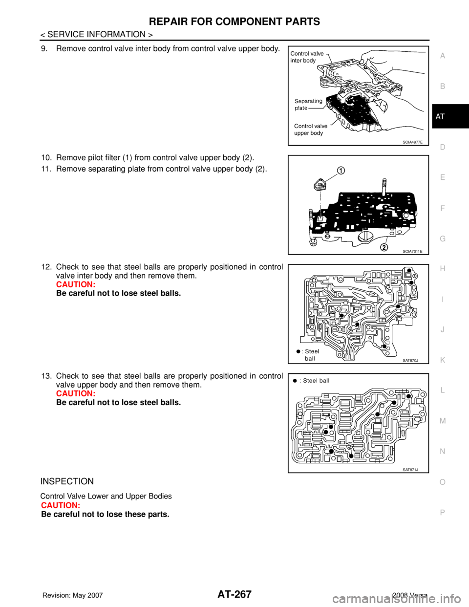
9. Remove control valve inter body from control valve upper body.
10. Remove pilot filter (1) from control valve upper body (2).
11. Remove separating plate from control valve upper body (2).
12. Check to see that steel balls are properly positioned in control
valve inter body and then remove them.
CAUTION:
Be careful not to lose steel balls.
13. Check to see that steel balls are properly positioned in control
valve upper body and then remove them.
CAUTION:
Be careful not to lose steel balls.
INSPECTION
Control Valve Lower and Upper Bodies
CAUTION:
Be careful not to lose these parts.
SCIA4977E
SCIA7011E
SAT870J
SAT871J
Page 282 of 2771
AT-270
< SERVICE INFORMATION >
REPAIR FOR COMPONENT PARTS
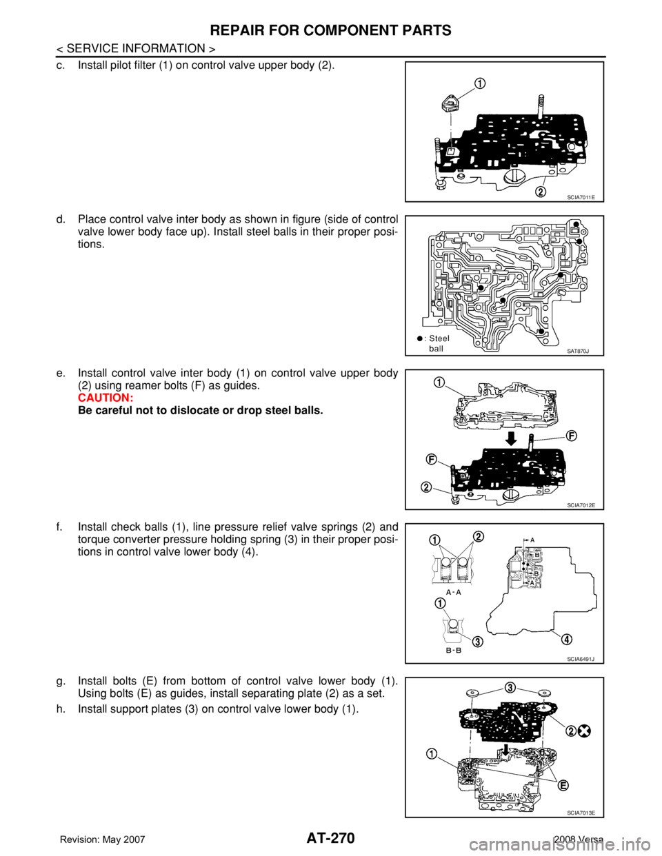
c. Install pilot filter (1) on control valve upper body (2).
d. Place control valve inter body as shown in figure (side of control
valve lower body face up). Install steel balls in their proper posi-
tions.
e. Install control valve inter body (1) on control valve upper body
(2) using reamer bolts (F) as guides.
CAUTION:
Be careful not to dislocate or drop steel balls.
f. Install check balls (1), line pressure relief valve springs (2) and
torque converter pressure holding spring (3) in their proper posi-
tions in control valve lower body (4).
g. Install bolts (E) from bottom of control valve lower body (1).
Using bolts (E) as guides, install separating plate (2) as a set.
h. Install support plates (3) on control valve lower body (1).
SCIA7011E
SAT870J
SCIA7012E
SCIA6491J
SCIA7013E
Page 855 of 2771
CVT-16
< SERVICE INFORMATION >
CVT FLUID
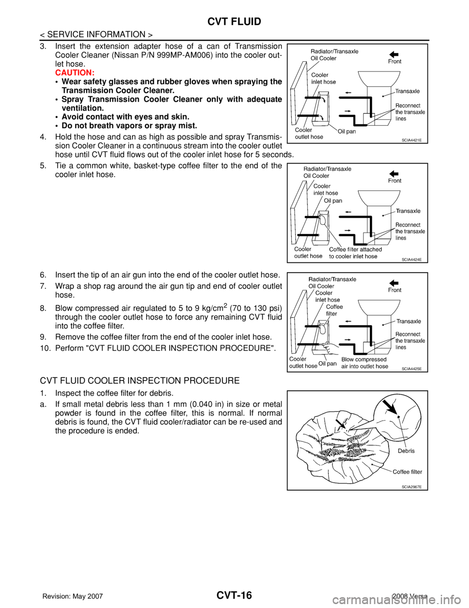
3. Insert the extension adapter hose of a can of Transmission
Cooler Cleaner (Nissan P/N 999MP-AM006) into the cooler out-
let hose.
CAUTION:
• Wear safety glasses and rubber gloves when spraying the
Transmission Cooler Cleaner.
• Spray Transmission Cooler Cleaner only with adequate
ventilation.
• Avoid contact with eyes and skin.
• Do not breath vapors or spray mist.
4. Hold the hose and can as high as possible and spray Transmis-
sion Cooler Cleaner in a continuous stream into the cooler outlet
hose until CVT fluid flows out of the cooler inlet hose for 5 seconds.
5. Tie a common white, basket-type coffee filter to the end of the
cooler inlet hose.
6. Insert the tip of an air gun into the end of the cooler outlet hose.
7. Wrap a shop rag around the air gun tip and end of cooler outlet
hose.
8. Blow compressed air regulated to 5 to 9 kg/cm
2 (70 to 130 psi)
through the cooler outlet hose to force any remaining CVT fluid
into the coffee filter.
9. Remove the coffee filter from the end of the cooler inlet hose.
10. Perform "CVT FLUID COOLER INSPECTION PROCEDURE".
CVT FLUID COOLER INSPECTION PROCEDURE
1. Inspect the coffee filter for debris.
a. If small metal debris less than 1 mm (0.040 in) in size or metal
powder is found in the coffee filter, this is normal. If normal
debris is found, the CVT fluid cooler/radiator can be re-used and
the procedure is ended.
SCIA4421E
SCIA4424E
SCIA4425E
SCIA2967E
Page 1154 of 2771
EC-80
< SERVICE INFORMATION >
BASIC SERVICE PROCEDURE
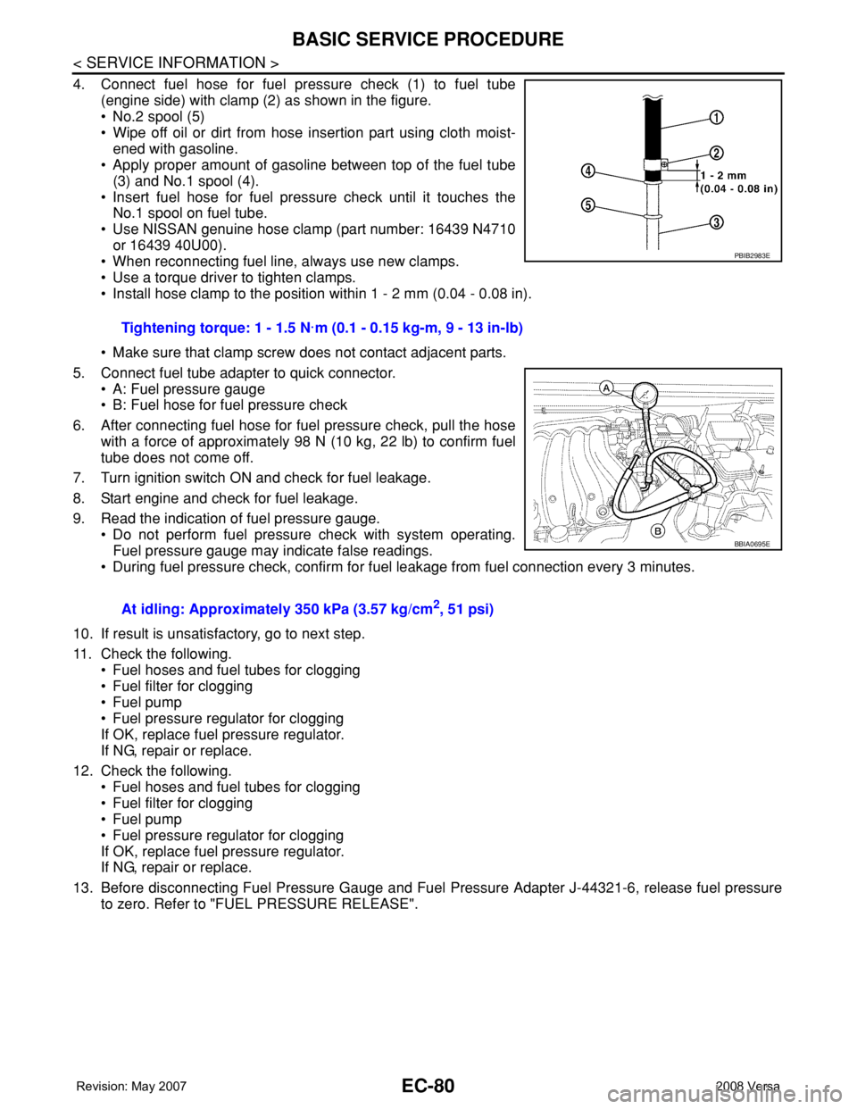
4. Connect fuel hose for fuel pressure check (1) to fuel tube
(engine side) with clamp (2) as shown in the figure.
• No.2 spool (5)
• Wipe off oil or dirt from hose insertion part using cloth moist-
ened with gasoline.
• Apply proper amount of gasoline between top of the fuel tube
(3) and No.1 spool (4).
• Insert fuel hose for fuel pressure check until it touches the
No.1 spool on fuel tube.
• Use NISSAN genuine hose clamp (part number: 16439 N4710
or 16439 40U00).
• When reconnecting fuel line, always use new clamps.
• Use a torque driver to tighten clamps.
• Install hose clamp to the position within 1 - 2 mm (0.04 - 0.08 in).
• Make sure that clamp screw does not contact adjacent parts.
5. Connect fuel tube adapter to quick connector.
• A: Fuel pressure gauge
• B: Fuel hose for fuel pressure check
6. After connecting fuel hose for fuel pressure check, pull the hose
with a force of approximately 98 N (10 kg, 22 lb) to confirm fuel
tube does not come off.
7. Turn ignition switch ON and check for fuel leakage.
8. Start engine and check for fuel leakage.
9. Read the indication of fuel pressure gauge.
• Do not perform fuel pressure check with system operating.
Fuel pressure gauge may indicate false readings.
• During fuel pressure check, confirm for fuel leakage from fuel connection every 3 minutes.
10. If result is unsatisfactory, go to next step.
11. Check the following.
• Fuel hoses and fuel tubes for clogging
• Fuel filter for clogging
• Fuel pump
• Fuel pressure regulator for clogging
If OK, replace fuel pressure regulator.
If NG, repair or replace.
12. Check the following.
• Fuel hoses and fuel tubes for clogging
• Fuel filter for clogging
• Fuel pump
• Fuel pressure regulator for clogging
If OK, replace fuel pressure regulator.
If NG, repair or replace.
13. Before disconnecting Fuel Pressure Gauge and Fuel Pressure Adapter J-44321-6, release fuel pressure
to zero. Refer to "FUEL PRESSURE RELEASE".Tightening torque: 1 - 1.5 N·m (0.1 - 0.15 kg-m, 9 - 13 in-lb)
At idling: Approximately 350 kPa (3.57 kg/cm
2, 51 psi)
PBIB2983E
BBIA0695E