2008 NISSAN LATIO air filter
[x] Cancel search: air filterPage 2270 of 2771

MA-10
< SERVICE INFORMATION >
RECOMMENDED FLUIDS AND LUBRICANTS
RECOMMENDED FLUIDS AND LUBRICANTS
Fluids and LubricantsINFOID:0000000001704725
*1: For further details, see “Engine Oil Recommendation”.
*2: DEXRON
TM III / MERCONTM , or equivalent may also be used. Outside the continental United States and Alaska contact a NISSAN
dealership for more information regarding suitable fluids, including recommended brand(s) of DEXRONTM III / MERCONTM Automatic
Transmission Fluid.
*3: Using transaxle fluid other than Genuine NISSAN CVT Fluid NS-2 will damage the CVT, which is not covered by the NISSAN
new vehicle limited warranty.
*4: Available in mainland U.S.A. through your NISSAN dealer.
*5: For further details, see “Air conditioner specification label”.
SAE Viscosity NumberINFOID:0000000001704726
NISSAN recommends the use of an energy conserving oil in order to improve fuel economy.
Select only engine oils that meet the American Petroleum Institute (API) certification and International Lubrica-
tion Standardization and Approval Committee (ILSAC) certification and SAE viscosity standard. These oils
have the API certification mark on the front of the container. Oils which do not have the specified quality label
should not be used as they could cause engine damage.
DescriptionCapacity (Approximate)
Recommended Fluids/Lubricants
Liter US measure Imp measure
Fuel 52.0 13 3/4 gal 11 1/2 galUnleaded gasoline with an octane rating of
at least 87 AKI (RON 91)
Engine oil
Drain and refillWith oil filter
change3.9 4 1/8 qt 3 3/8 qt
• Engine oil with API Certification Mark *1
• Viscosity SAE 5W-30 Without oil filter
change3.7 3 7/8 qt 3 1/4 qt
Dry engine (engine overhaul) 4.9 5 1/8 qt 4 3/8 qt
Cooling system
(with reservoir at max level)6.8 7 1/4 qt 6 qtGenuine NISSAN Long Life Anti-freeze
Coolant or equivalent
Manual transaxle fluid (MTF) 2.0 4 1/4 pt 3 1/2 ptEFF XT4447 M+ 75W-80 or API GL-4, Vis-
cosity SAE 75W-80
Automatic transaxle fluid (ATF) 7.9 8 3/8 qt 7 qtGenuine NISSAN Matic “D” ATF (Continen-
tal U.S. and Alaska) or Canada NISSAN
Automatic Transmission Fluid *2
CVT fluid 8.3 8 3/4 qt 7 1/4 qt Genuine NISSAN CVT Fluid NS-2 *3
Brake and clutch fluid — — —Genuine NISSAN Super Heavy Duty Brake
Fluid*4 or equivalent DOT 3 (US FMVSS
No. 116)
Multi-purpose grease — — — NLGI No. 2 (Lithium soap base)
Windshield washer fluid 4.5 4 3/4 qt 4 qtGenuine NISSAN Windshield Washer Con-
centrate Cleaner & Anti-Freeze or equiva-
lent
Air conditioning system refrigerant 0.45 ± 0.05 kg 0.99 ± 0.11 lb 0.99 ± 0.11 lb HFC-134a (R-134a) *5
Air conditioning
system oilTyp e 1
120 m4.1 fl oz 4.2 fl ozNISSAN A/C System Lubricant Type R or
equivalent *5
Typ e 2
100 m3.4 fl oz 3.5 fl ozNISSAN A/C System Lubricant Type S or
equivalent *5
Page 2274 of 2771
MA-14
< SERVICE INFORMATION >
ENGINE MAINTENANCE
1. Install reservoir tank if removed. Refer to CO-11 .
2. Install radiator drain plug.
•If water drain plug on cylinder block is removed, close and tighten it. Refer to EM-76
.
CAUTION:
Be sure to clean radiator drain plug and install with new O-ring. Refer to CO-11, "
Component" .
3. Fill radiator and reservoir tank with water and reinstall radiator cap.
4. Run engine and warm it up to normal operating temperature.
5. Rev engine two or three times under no-load.
6. Stop engine and wait until it cools down.
7. Drain water from the cooling system. Refer to "DRAINING ENGINE COOLANT" .
8. Repeat steps 1 through 7 until clear water begins to drain from radiator.
InspectionINFOID:0000000001704732
LEVEL CHECK
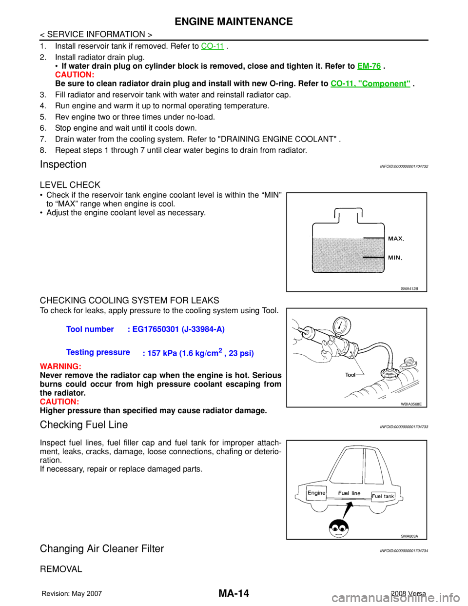
• Check if the reservoir tank engine coolant level is within the “MIN”
to “MAX” range when engine is cool.
• Adjust the engine coolant level as necessary.
CHECKING COOLING SYSTEM FOR LEAKS
To check for leaks, apply pressure to the cooling system using Tool.
WARNING:
Never remove the radiator cap when the engine is hot. Serious
burns could occur from high pressure coolant escaping from
the radiator.
CAUTION:
Higher pressure than specified may cause radiator damage.
Checking Fuel LineINFOID:0000000001704733
Inspect fuel lines, fuel filler cap and fuel tank for improper attach-
ment, leaks, cracks, damage, loose connections, chafing or deterio-
ration.
If necessary, repair or replace damaged parts.
Changing Air Cleaner FilterINFOID:0000000001704734
REMOVAL
SMA412B
Tool number : EG17650301 (J-33984-A)
Testing pressure
: 157 kPa (1.6 kg/cm
2 , 23 psi)
WBIA0568E
SMA803A
Page 2275 of 2771
ENGINE MAINTENANCE
MA-15
< SERVICE INFORMATION >
C
D
E
F
G
H
I
J
K
MA
B
MA
N
O
P
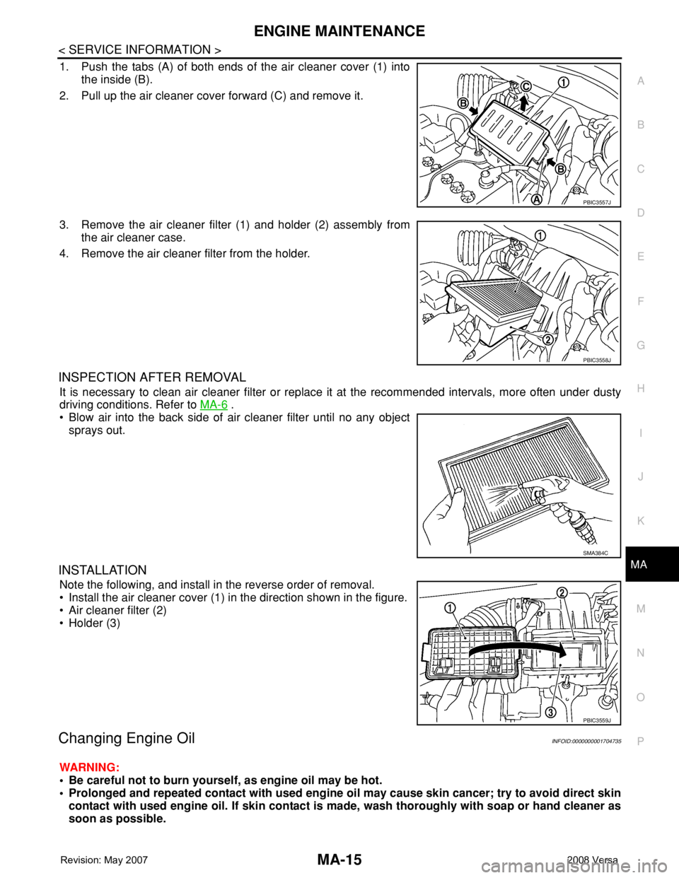
1. Push the tabs (A) of both ends of the air cleaner cover (1) into
the inside (B).
2. Pull up the air cleaner cover forward (C) and remove it.
3. Remove the air cleaner filter (1) and holder (2) assembly from
the air cleaner case.
4. Remove the air cleaner filter from the holder.
INSPECTION AFTER REMOVAL
It is necessary to clean air cleaner filter or replace it at the recommended intervals, more often under dusty
driving conditions. Refer to MA-6
.
• Blow air into the back side of air cleaner filter until no any object
sprays out.
INSTALLATION
Note the following, and install in the reverse order of removal.
• Install the air cleaner cover (1) in the direction shown in the figure.
• Air cleaner filter (2)
• Holder (3)
Changing Engine OilINFOID:0000000001704735
WARNING:
• Be careful not to burn yourself, as engine oil may be hot.
• Prolonged and repeated contact with used engine oil may cause skin cancer; try to avoid direct skin
contact with used engine oil. If skin contact is made, wash thoroughly with soap or hand cleaner as
soon as possible.
PBIC3557J
PBIC3558J
SMA384C
PBIC3559J
Page 2279 of 2771
CHASSIS AND BODY MAINTENANCE
MA-19
< SERVICE INFORMATION >
C
D
E
F
G
H
I
J
K
MA
B
MA
N
O
P
CHASSIS AND BODY MAINTENANCE
Changing In-cabin MicrofilterINFOID:0000000001704739
1. Remove the glove box assembly. Refer to IP-10 .
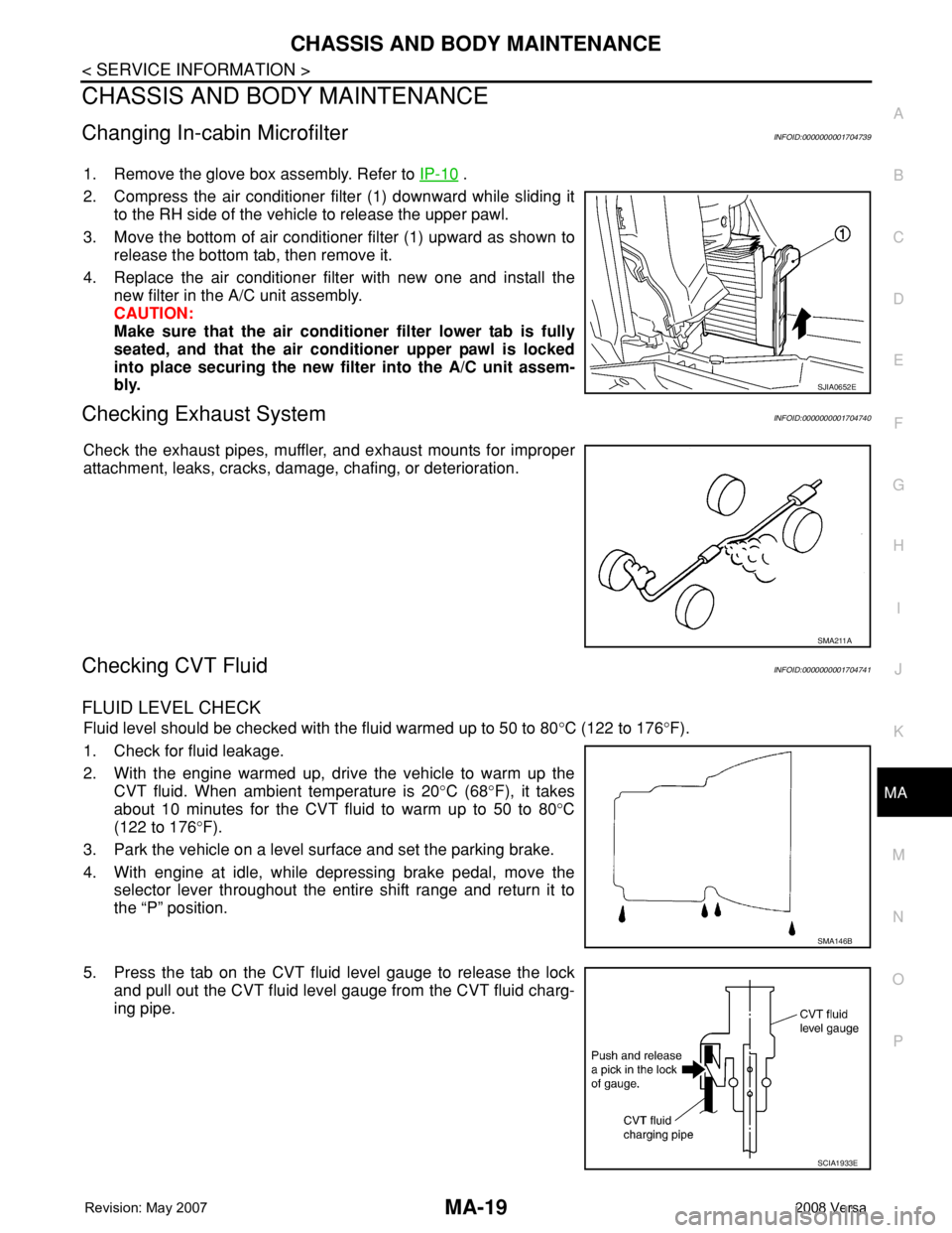
2. Compress the air conditioner filter (1) downward while sliding it
to the RH side of the vehicle to release the upper pawl.
3. Move the bottom of air conditioner filter (1) upward as shown to
release the bottom tab, then remove it.
4. Replace the air conditioner filter with new one and install the
new filter in the A/C unit assembly.
CAUTION:
Make sure that the air conditioner filter lower tab is fully
seated, and that the air conditioner upper pawl is locked
into place securing the new filter into the A/C unit assem-
bly.
Checking Exhaust SystemINFOID:0000000001704740
Check the exhaust pipes, muffler, and exhaust mounts for improper
attachment, leaks, cracks, damage, chafing, or deterioration.
Checking CVT FluidINFOID:0000000001704741
FLUID LEVEL CHECK
Fluid level should be checked with the fluid warmed up to 50 to 80°C (122 to 176°F).
1. Check for fluid leakage.
2. With the engine warmed up, drive the vehicle to warm up the
CVT fluid. When ambient temperature is 20°C (68°F), it takes
about 10 minutes for the CVT fluid to warm up to 50 to 80°C
(122 to 176°F).
3. Park the vehicle on a level surface and set the parking brake.
4. With engine at idle, while depressing brake pedal, move the
selector lever throughout the entire shift range and return it to
the “P” position.
5. Press the tab on the CVT fluid level gauge to release the lock
and pull out the CVT fluid level gauge from the CVT fluid charg-
ing pipe.
SJIA0652E
SMA211A
SMA146B
SCIA1933E
Page 2339 of 2771

MTC-1
AIR CONDITIONER
C
D
E
F
G
H
I
K
L
M
SECTION MTC
A
B
MTC
N
O
P
CONTENTS
MANUAL AIR CONDITIONER
SERVICE INFORMATION ............................3
PRECAUTIONS ...................................................3
Precaution for Supplemental Restraint System
(SRS) "AIR BAG" and "SEAT BELT PRE-TEN-
SIONER" ...................................................................
3
Precaution for Procedure without Cowl Top Cover ......3
Precaution for Working with HFC-134a (R-134a) ......3
General Refrigerant Precaution ................................4
Oil Precaution ............................................................4
Precaution for Refrigerant Connection ......................4
Precaution for Service of Compressor ......................7
Precaution for Service Equipment .............................7
Precaution for Leak Detection Dye ...........................9
PREPARATION ..................................................10
Special Service Tool ...............................................10
HFC-134a (R-134a) Service Tool and Equipment ....10
Commercial Service Tool ........................................13
REFRIGERATION SYSTEM ..............................14
Refrigerant Cycle ....................................................14
Refrigerant System Protection ................................14
Component Part Location .......................................15
OIL ......................................................................16
Maintenance of Oil Quantity in Compressor ...........16
AIR CONDITIONER CONTROL .........................19
Control Operation ....................................................19
Discharge Air Flow ..................................................20
System Description .................................................20
CAN Communication System Description ...............21
TROUBLE DIAGNOSIS .....................................22
CONSULT-III Function (BCM) .................................22
How to Perform Trouble Diagnosis for Quick and
Accurate Repair ......................................................
22
Component Parts and Harness Connector Loca-
tion ..........................................................................
23
Schematic ...............................................................25
Wiring Diagram - Heater - .......................................26
Wiring Diagram - A/C,M - ........................................27
Operational Check ...................................................30
Mode Door ...............................................................31
Air Mix Door .............................................................32
Intake Door ..............................................................33
Front Blower Motor Circuit .......................................33
Magnet Clutch Circuit (If Equipped) .........................37
Insufficient Cooling ..................................................45
Insufficient Heating ..................................................52
Noise .......................................................................53
CONTROLLER ..................................................55
Removal and Installation .........................................55
Disassembly and Assembly .....................................56
THERMO CONTROL AMPLIFIER ....................57
Removal and Installation .........................................57
A/C UNIT ASSEMBLY ......................................58
Removal and Installation .........................................58
Disassembly and Assembly .....................................60
BLOWER MOTOR ............................................62
Removal and Installation .........................................62
INTAKE DOOR ..................................................63
Intake Door Cable Adjustment .................................63
AIR MIX DOOR .................................................64
Air Mix Door Cable Adjustment ...............................64
MODE DOOR ....................................................65
Mode Door Cable Adjustment .................................65
BLOWER FAN RESISTOR ...............................66
Removal and Installation .........................................66
HEATER CORE .................................................67
Removal and Installation .........................................67
AIR CONDITIONER FILTER .............................68
Removal and Installation .........................................68
Page 2398 of 2771
MTC-60
< SERVICE INFORMATION >
A/C UNIT ASSEMBLY
Disassembly and Assembly
INFOID:0000000001704313
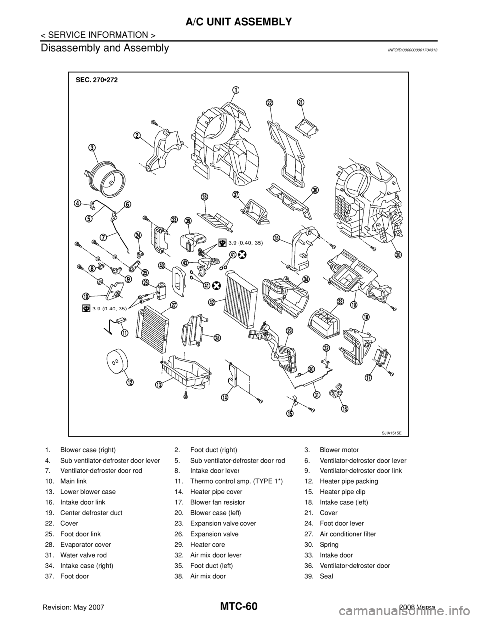
1. Blower case (right) 2. Foot duct (right) 3. Blower motor
4. Sub ventilator·defroster door lever 5. Sub ventilator·defroster door rod 6. Ventilator·defroster door lever
7. Ventilator·defroster door rod 8. Intake door lever 9. Ventilator·defroster door link
10. Main link 11. Thermo control amp. (TYPE 1*) 12. Heater pipe packing
13. Lower blower case 14. Heater pipe cover 15. Heater pipe clip
16. Intake door link 17. Blower fan resistor 18. Intake case (left)
19. Center defroster duct 20. Blower case (left) 21. Cover
22. Cover 23. Expansion valve cover 24. Foot door lever
25. Foot door link 26. Expansion valve 27. Air conditioner filter
28. Evaporator cover 29. Heater core 30. Spring
31. Water valve rod 32. Air mix door lever 33. Intake door
34. Intake case (right) 35. Foot duct (left) 36. Ventilator·defroster door
37. Foot door 38. Air mix door 39. Seal
SJIA1515E
Page 2406 of 2771
MTC-68
< SERVICE INFORMATION >
AIR CONDITIONER FILTER
AIR CONDITIONER FILTER
Removal and InstallationINFOID:0000000001704320
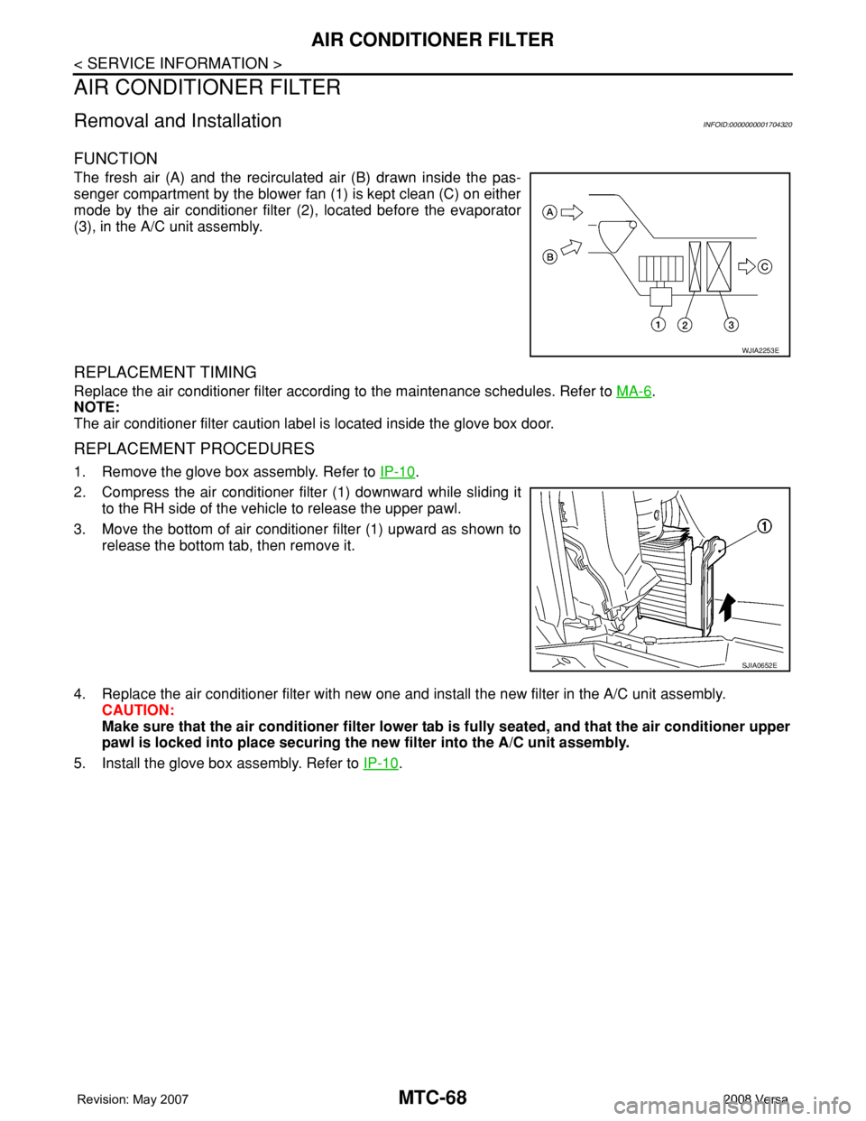
FUNCTION
The fresh air (A) and the recirculated air (B) drawn inside the pas-
senger compartment by the blower fan (1) is kept clean (C) on either
mode by the air conditioner filter (2), located before the evaporator
(3), in the A/C unit assembly.
REPLACEMENT TIMING
Replace the air conditioner filter according to the maintenance schedules. Refer to MA-6.
NOTE:
The air conditioner filter caution label is located inside the glove box door.
REPLACEMENT PROCEDURES
1. Remove the glove box assembly. Refer to IP-10.
2. Compress the air conditioner filter (1) downward while sliding it
to the RH side of the vehicle to release the upper pawl.
3. Move the bottom of air conditioner filter (1) upward as shown to
release the bottom tab, then remove it.
4. Replace the air conditioner filter with new one and install the new filter in the A/C unit assembly.
CAUTION:
Make sure that the air conditioner filter lower tab is fully seated, and that the air conditioner upper
pawl is locked into place securing the new filter into the A/C unit assembly.
5. Install the glove box assembly. Refer to IP-10
.
WJIA2253E
SJIA0652E
Page 2421 of 2771
REFRIGERANT LINES
MTC-83
< SERVICE INFORMATION >
C
D
E
F
G
H
I
K
L
MA
B
MTC
N
O
P
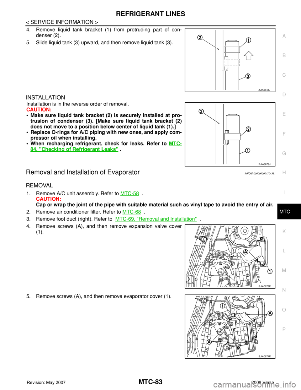
4. Remove liquid tank bracket (1) from protruding part of con-
denser (2).
5. Slide liquid tank (3) upward, and then remove liquid tank (3).
INSTALLATION
Installation is in the reverse order of removal.
CAUTION:
• Make sure liquid tank bracket (2) is securely installed at pro-
trusion of condenser (3). [Make sure liquid tank bracket (2)
does not move to a position below center of liquid tank (1).]
• Replace O-rings for A/C piping with new ones, and apply com-
pressor oil when installing.
• When recharging refrigerant, check for leaks. Refer to MTC-
84, "Checking of Refrigerant Leaks" .
Removal and Installation of EvaporatorINFOID:0000000001704331
REMOVAL
1. Remove A/C unit assembly. Refer to MTC-58 .
CAUTION:
Cap or wrap the joint of the pipe with suitable material such as vinyl tape to avoid the entry of air.
2. Remove air conditioner filter. Refer to MTC-68
.
3. Remove foot duct (right). Refer to MTC-69, "
Removal and Installation" .
4. Remove screws (A), and then remove expansion valve cover
(1).
5. Remove screws (A), and then remove evaporator cover (1).
ZJIA0843J
RJIA3879J
SJIA0673E
SJIA0674E