Page 1326 of 2771
EC-252
< SERVICE INFORMATION >
DTC P0139 HO2S2
Wiring Diagram
INFOID:0000000001702756
Specification data are reference values and are measured between each terminal and ground.
Pulse signal is measured by CONSULT-II.
CAUTION:
BBWA2629E
Page 1328 of 2771

EC-254
< SERVICE INFORMATION >
DTC P0139 HO2S2
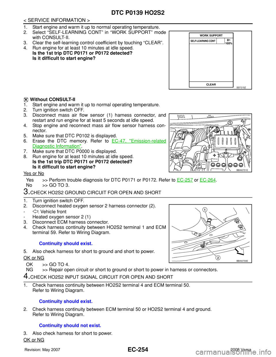
1. Start engine and warm it up to normal operating temperature.
2. Select “SELF-LEARNING CONT” in “WORK SUPPORT” mode
with CONSULT-II.
3. Clear the self-learning control coefficient by touching “CLEAR”.
4. Run engine for at least 10 minutes at idle speed.
Is the 1st trip DTC P0171 or P0172 detected?
Is it difficult to start engine?
Without CONSULT-II
1. Start engine and warm it up to normal operating temperature.
2. Turn ignition switch OFF.
3. Disconnect mass air flow sensor (1) harness connector, and
restart and run engine for at least 5 seconds at idle speed.
4. Stop engine and reconnect mass air flow sensor harness con-
nector.
5. Make sure that DTC P0102 is displayed.
6. Erase the DTC memory. Refer to EC-47, "
Emission-related
Diagnostic Information".
7. Make sure that DTC P0000 is displayed.
8. Run engine for at least 10 minutes at idle speed.
Is the 1st trip DTC P0171 or P0172 detected?
Is it difficult to start engine?
Ye s o r N o
Yes >> Perform trouble diagnosis for DTC P0171 or P0172. Refer to EC-257 or EC-264.
No >> GO TO 3.
3.CHECK HO2S2 GROUND CIRCUIT FOR OPEN AND SHORT
1. Turn ignition switch OFF.
2. Disconnect heated oxygen sensor 2 harness connector (2).
- : Vehicle front
- Heated oxygen sensor 2 (1)
3. Disconnect ECM harness connector.
4. Check harness continuity between HO2S2 terminal 1 and ECM
terminal 59. Refer to Wiring Diagram.
5. Also check harness for short to ground and short to power.
OK or NG
OK >> GO TO 4.
NG >> Repair open circuit or short to ground or short to power in harness or connectors.
4.CHECK HO2S2 INPUT SIGNAL CIRCUIT FOR OPEN AND SHORT
1. Check harness continuity between HO2S2 terminal 4 and ECM terminal 50.
Refer to Wiring Diagram.
2. Check harness continuity between ECM terminal 50 or HO2S2 terminal 4 and ground.
Refer to Wiring Diagram.
3. Also check harness for short to power.
OK or NG
SEF215Z
BBIA0701E
Continuity should exist.
BBIA0700E
Continuity should exist.
Continuity should not exist.
Page 1333 of 2771
DTC P0171 FUEL INJECTION SYSTEM FUNCTION
EC-259
< SERVICE INFORMATION >
C
D
E
F
G
H
I
J
K
L
MA
EC
N
P O
Wiring DiagramINFOID:0000000001702762
Specification data are reference values and are measured between each terminal and ground.
Pulse signal is measured by CONSULT-II.
CAUTION:
BBWA2999E
Page 1335 of 2771

DTC P0171 FUEL INJECTION SYSTEM FUNCTION
EC-261
< SERVICE INFORMATION >
C
D
E
F
G
H
I
J
K
L
MA
EC
N
P O
1. Listen for an intake air leak after the mass air flow sensor.
2. Check PCV hose connection.
OK or NG
OK >> GO TO 3.
NG >> Repair or replace.
3.CHECK AIR FUEL RATIO (A/F) SENSOR 1 CIRCUIT FOR OPEN AND SHORT
1. Turn ignition switch OFF.
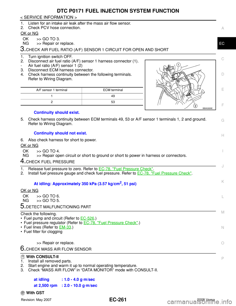
2. Disconnect air fuel ratio (A/F) sensor 1 harness connector (1).
- Air fuel ratio (A/F) sensor 1 (2)
3. Disconnect ECM harness connector.
4. Check harness continuity between the following terminals.
Refer to Wiring Diagram.
5. Check harness continuity between ECM terminals 49, 53 or A/F sensor 1 terminals 1, 2 and ground.
Refer to Wiring Diagram.
6. Also check harness for short to power.
OK or NG
OK >> GO TO 4.
NG >> Repair open circuit or short to ground or short to power in harness or connectors.
4.CHECK FUEL PRESSURE
1. Release fuel pressure to zero. Refer to EC-78, "
Fuel Pressure Check".
2. Install fuel pressure gauge and check fuel pressure. Refer to EC-78, "
Fuel Pressure Check".
OK or NG
OK >> GO TO 6.
NG >> GO TO 5.
5.DETECT MALFUNCTIONING PART
Check the following.
• Fuel pump and circuit (Refer to EC-526
.)
• Fuel pressure regulator (Refer to EC-78, "
Fuel Pressure Check".)
• Fuel lines (Refer to EM-33
.)
• Fuel filter for clogging
>> Repair or replace.
6.CHECK MASS AIR FLOW SENSOR
With CONSULT-II
1. Install all removed parts.
2. Start engine and warm it up to normal operating temperature.
3. Check “MASS AIR FLOW” in “DATA MONITOR” mode with CONSULT-II.
With GST
A/F sensor 1 terminal ECM terminal
149
253
Continuity should exist.
Continuity should not exist.
BBIA0699E
At idling: Approximately 350 kPa (3.57 kg/cm2, 51 psi)
at idling : 1.0 - 4.0 g·m/sec
at 2,500 rpm : 2.0 - 10.0 g·m/sec
Page 1340 of 2771
EC-266
< SERVICE INFORMATION >
DTC P0172 FUEL INJECTION SYSTEM FUNCTION
Wiring Diagram
INFOID:0000000001702766
Specification data are reference values and are measured between each terminal and ground.
Pulse signal is measured by CONSULT-II.
CAUTION:
BBWA2999E
Page 1342 of 2771

EC-268
< SERVICE INFORMATION >
DTC P0172 FUEL INJECTION SYSTEM FUNCTION
Listen for an intake air leak after the mass air flow sensor.
OK or NG
OK >> GO TO 3.
NG >> Repair or replace.
3.CHECK AIR FUEL RATIO (A/F) SENSOR 1 CIRCUIT FOR OPEN AND SHORT
1. Turn ignition switch OFF.
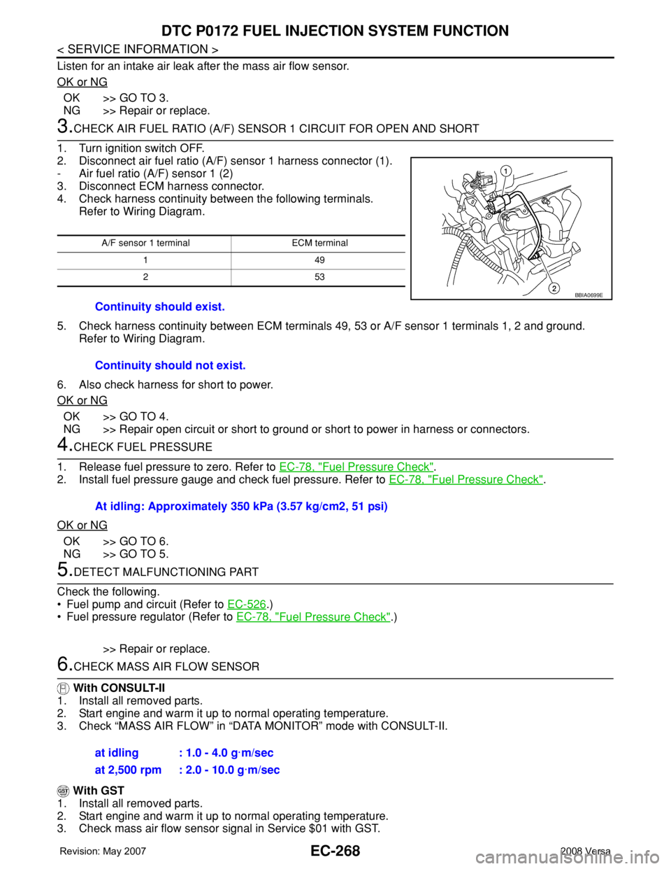
2. Disconnect air fuel ratio (A/F) sensor 1 harness connector (1).
- Air fuel ratio (A/F) sensor 1 (2)
3. Disconnect ECM harness connector.
4. Check harness continuity between the following terminals.
Refer to Wiring Diagram.
5. Check harness continuity between ECM terminals 49, 53 or A/F sensor 1 terminals 1, 2 and ground.
Refer to Wiring Diagram.
6. Also check harness for short to power.
OK or NG
OK >> GO TO 4.
NG >> Repair open circuit or short to ground or short to power in harness or connectors.
4.CHECK FUEL PRESSURE
1. Release fuel pressure to zero. Refer to EC-78, "
Fuel Pressure Check".
2. Install fuel pressure gauge and check fuel pressure. Refer to EC-78, "
Fuel Pressure Check".
OK or NG
OK >> GO TO 6.
NG >> GO TO 5.
5.DETECT MALFUNCTIONING PART
Check the following.
• Fuel pump and circuit (Refer to EC-526
.)
• Fuel pressure regulator (Refer to EC-78, "
Fuel Pressure Check".)
>> Repair or replace.
6.CHECK MASS AIR FLOW SENSOR
With CONSULT-II
1. Install all removed parts.
2. Start engine and warm it up to normal operating temperature.
3. Check “MASS AIR FLOW” in “DATA MONITOR” mode with CONSULT-II.
With GST
1. Install all removed parts.
2. Start engine and warm it up to normal operating temperature.
3. Check mass air flow sensor signal in Service $01 with GST.
A/F sensor 1 terminal ECM terminal
149
253
Continuity should exist.
Continuity should not exist.
BBIA0699E
At idling: Approximately 350 kPa (3.57 kg/cm2, 51 psi)
at idling : 1.0 - 4.0 g·m/sec
at 2,500 rpm : 2.0 - 10.0 g·m/sec
Page 1345 of 2771
DTC P0181 FTT SENSOR
EC-271
< SERVICE INFORMATION >
C
D
E
F
G
H
I
J
K
L
MA
EC
N
P O
WITH GST
Follow the procedure “WITH CONSULT-II” above.
Wiring DiagramINFOID:0000000001702771
Diagnosis ProcedureINFOID:0000000001702772
1.CHECK GROUND CONNECTIONS
BBWA2636E
Page 1347 of 2771

DTC P0181 FTT SENSOR
EC-273
< SERVICE INFORMATION >
C
D
E
F
G
H
I
J
K
L
MA
EC
N
P O
1. Turn ignition switch OFF.
2. Check harness continuity between “fuel level sensor unit and fuel pump” terminal 5 and combination
meter terminal 24. Refer to Wiring Diagram.
3. Also check harness for short to ground and short to power.
OK or NG
OK >> GO TO 6.
NG >> GO TO 5.
5.DETECT MALFUNCTIONING PART
Check the following.
• Harness connectors B102, M13
• Harness for open or short between “fuel level sensor unit and fuel pump” and ground.
>> Repair open circuit or short to ground or short to power in harness or connectors.
6.CHECK FUEL TANK TEMPERATURE SENSOR
Refer to, EC-273, "
Component Inspection".
OK or NG
OK >> GO TO 7.
NG >> Replace “fuel level sensor unit and fuel pump”.
7.CHECK INTERMITTENT INCIDENT
Perform EC-136
.
>>INSPECTION END
Component InspectionINFOID:0000000001702773
FUEL TANK TEMPERATURE SENSOR
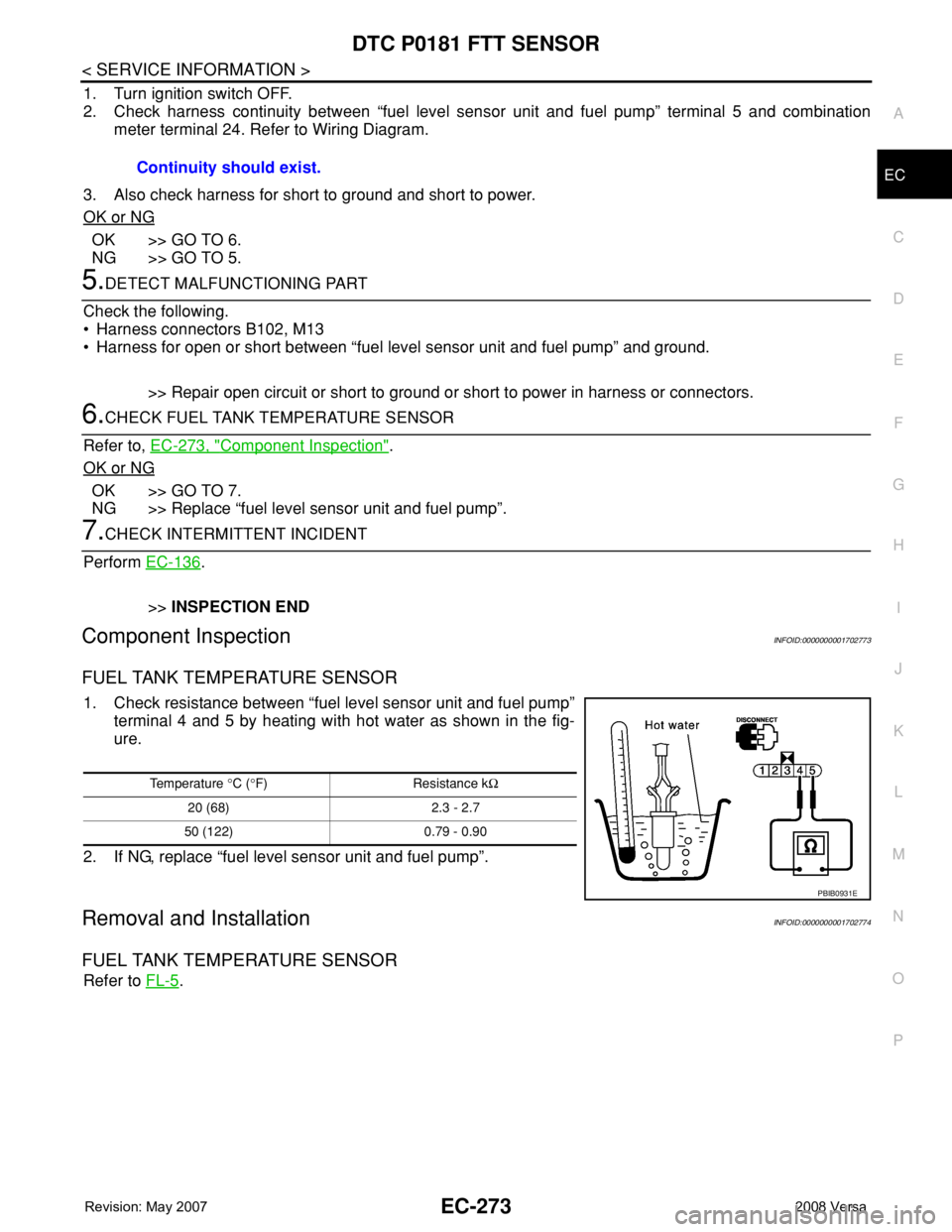
1. Check resistance between “fuel level sensor unit and fuel pump”
terminal 4 and 5 by heating with hot water as shown in the fig-
ure.
2. If NG, replace “fuel level sensor unit and fuel pump”.
Removal and InstallationINFOID:0000000001702774
FUEL TANK TEMPERATURE SENSOR
Refer to FL-5. Continuity should exist.
Temperature °C (°F) Resistance kΩ
20 (68) 2.3 - 2.7
50 (122) 0.79 - 0.90
PBIB0931E