2008 NISSAN LATIO engine
[x] Cancel search: enginePage 209 of 2771
TROUBLE DIAGNOSIS FOR SYMPTOMS
AT-197
< SERVICE INFORMATION >
D
E
F
G
H
I
J
K
L
MA
B
AT
N
O
P
- Shift valve A
- Shift solenoid valve A
- Overrun clutch control valve
- Overrun clutch solenoid valve
3. Disassemble A/T. Refer to AT-240, "
Disassembly" .
4. Check the following items:
- Servo piston assembly
- Brake band
OK or NG
OK >> GO TO 7.
NG >> Repair or replace damaged parts.
7.CHECK SYMPTOM
Check again. Refer to AT-59, "
Cruise Test - Part 3" .
OK or NG
OK >>INSPECTION END
NG >> GO TO 8.
8.CHECK TCM
1. Check TCM input/output signals. Refer to AT-71, "
TCM Terminal and Reference Value" .
2. If NG, recheck TCM pin terminals for damage or loose connection with harness connector.
OK or NG
OK >>INSPECTION END
NG >> Repair or replace damaged parts.
Vehicle Does Not Decelerate by Engine BrakeINFOID:0000000001703353
SYMPTOM:
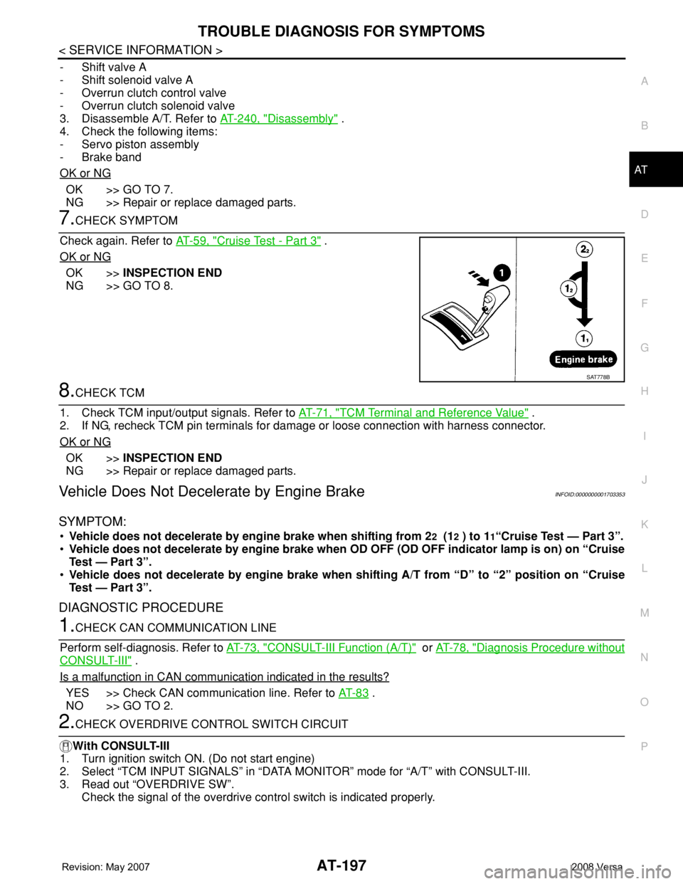
•Vehicle does not decelerate by engine brake when shifting from 22 (12 ) to 11“Cruise Test — Part 3”.
•Vehicle does not decelerate by engine brake when OD OFF (OD OFF indicator lamp is on) on “Cruise
Test — Part 3”.
•Vehicle does not decelerate by engine brake when shifting A/T from “D” to “2” position on “Cruise
Test — Part 3”.
DIAGNOSTIC PROCEDURE
1.CHECK CAN COMMUNICATION LINE
Perform self-diagnosis. Refer to AT-73, "
CONSULT-III Function (A/T)" or AT-78, "Diagnosis Procedure without
CONSULT-III" .
Is a malfunction in CAN communication indicated in the results?
YES >> Check CAN communication line. Refer to AT- 8 3 .
NO >> GO TO 2.
2.CHECK OVERDRIVE CONTROL SWITCH CIRCUIT
With CONSULT-III
1. Turn ignition switch ON. (Do not start engine)
2. Select “TCM INPUT SIGNALS” in “DATA MONITOR” mode for “A/T” with CONSULT-III.
3. Read out “OVERDRIVE SW”.
Check the signal of the overdrive control switch is indicated properly.
SAT778B
Page 210 of 2771
AT-198
< SERVICE INFORMATION >
TROUBLE DIAGNOSIS FOR SYMPTOMS
Without CONSULT-III
1. Turn ignition switch ON. (Do not start engine)
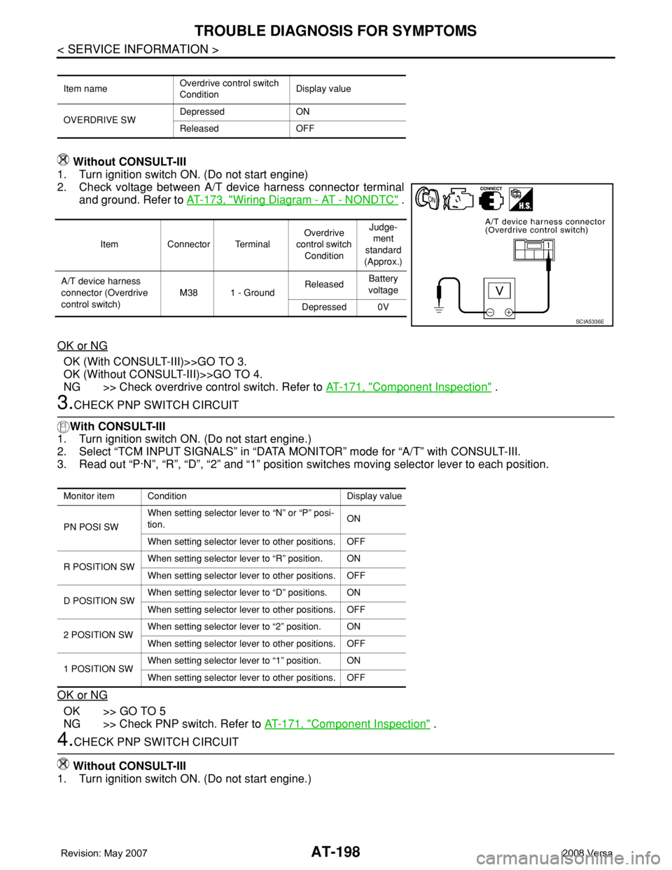
2. Check voltage between A/T device harness connector terminal
and ground. Refer to AT-173, "
Wiring Diagram - AT - NONDTC" .
OK or NG
OK (With CONSULT-III)>>GO TO 3.
OK (Without CONSULT-III)>>GO TO 4.
NG >> Check overdrive control switch. Refer to AT-171, "
Component Inspection" .
3.CHECK PNP SWITCH CIRCUIT
With CONSULT-III
1. Turn ignition switch ON. (Do not start engine.)
2. Select “TCM INPUT SIGNALS” in “DATA MONITOR” mode for “A/T” with CONSULT-III.
3. Read out “P·N”, “R”, “D”, “2” and “1” position switches moving selector lever to each position.
OK or NG
OK >> GO TO 5
NG >> Check PNP switch. Refer to AT-171, "
Component Inspection" .
4.CHECK PNP SWITCH CIRCUIT
Without CONSULT-III
1. Turn ignition switch ON. (Do not start engine.)
Item nameOverdrive control switch
ConditionDisplay value
OVERDRIVE SWDepressed ON
Released OFF
Item Connector TerminalOverdrive
control switch
ConditionJudge-
ment
standard
(Approx.)
A/T device harness
connector (Overdrive
control switch)M38 1 - GroundReleasedBattery
voltage
Depressed 0V
SCIA5336E
Monitor item Condition Display value
PN POSI SWWhen setting selector lever to “N” or “P” posi-
tion.ON
When setting selector lever to other positions. OFF
R POSITION SWWhen setting selector lever to “R” position. ON
When setting selector lever to other positions. OFF
D POSITION SWWhen setting selector lever to “D” positions. ON
When setting selector lever to other positions. OFF
2 POSITION SWWhen setting selector lever to “2” position. ON
When setting selector lever to other positions. OFF
1 POSITION SWWhen setting selector lever to “1” position. ON
When setting selector lever to other positions. OFF
Page 219 of 2771

SHIFT CONTROL SYSTEM
AT-207
< SERVICE INFORMATION >
D
E
F
G
H
I
J
K
L
MA
B
AT
N
O
P
1. Place the selector lever knob (1) in “N” position.
2. Slide knob cover (2) downward.
3. Pull out lock pin (3) from selector lever knob (1).
4. Remove selector lever knob (1) and knob cover (2) as a set from
selector lever.
CAUTION:
Do not push selector button.
INSTALLATION
1. Insert lock pin (1) to selector lever knob (2).
2. Install knob cover (3) to selector lever knob (2).
3. Place the selector lever in “N” position.
4. Install selector lever knob over selector lever until a click is felt.
CAUTION:
• Do not tilt selector lever knob when installing. Install it
straight, and do not tap or apply any shock to install it.
• Do not push selector button.
Adjustment of A/T PositionINFOID:0000000001703359
Move selector lever from “P” position to “1” position. You should be able to feel the detents in each position. If
the detents cannot be felt or if the position indicator is improperly aligned, the control cable needs adjustment.
CAUTION:
Make sure that parking brake is applied before adjustment.
1. Remove the air duct assembly. Refer to EM-16
.
2. Remove the control cable nut (A) and control cable (1) and
place the manual lever (2) in the "P' position.
3. Place selector lever in “P” position.
4. Hold control cable (1) at the end and pull it with a force of 9.8 N
(approximately 1 kg, 2.2 lb). Release the control cable and tem-
porarily tighten control cable nut (A).
5. Tighten control cable nut (A) to the specified torque.
CAUTION:
Secure manual lever when tightening nut.
6. Move selector lever from “P” to “1” position again. Make sure that selector lever moves smoothly.
7. Check A/T position. Refer to AT-207, "
Checking of A/T Position".
8. Install air duct assembly. Refer to EM-16
.
Checking of A/T PositionINFOID:0000000001703360
1. Place selector lever in “P” position, and turn ignition switch ON (Do not start engine).
2. Make sure selector lever can be shifted to other than “P” position when brake pedal is depressed. Also
make sure selector lever can be shifted from “P” position only when brake pedal is depressed.
3. Move selector lever and check for excessive effort, sticking, noise or rattle.
4. Confirm selector lever stops at each position with the feel of engagement when it is moved through all the
positions. Check whether or not the actual position selector lever is in matches the position shown by the
shift position indicator and the transaxle.
SCIA6971E
SCIA6972E
Control cable nut : Refer to AT-203, "Control De-
vice Removal and Installation".WCIA0635E
Page 220 of 2771

AT-208
< SERVICE INFORMATION >
SHIFT CONTROL SYSTEM
5. The method of operating selector lever to individual positions
correctly should be as shown.
• (A): Press selector button to operate selector lever, while
depressing the brake pedal.
• (B): Press selector button to operate selector lever.
• (C): Selector lever can be operated without pressing selector
button.
6. Confirm back-up lamps illuminate only when selector lever is
placed in “R” position. Confirm back-up lamps do not illuminate
when selector lever is in “P” or “N” position even if it is pushed
toward “R” position without pressing selector button.
7. Confirm engine can only be started with selector lever in “P” and
“N” positions.
8. Make sure A/T is locked completely in “P” position.
WCIA0636E
Page 223 of 2771
A/T SHIFT LOCK SYSTEM
AT-211
< SERVICE INFORMATION >
D
E
F
G
H
I
J
K
L
MA
B
AT
N
O
P
•Selector lever can be moved from “P” position with ignition key in ON position and brake pedal
released.
•Selector lever can be moved from “P” position when ignition switch is removed from key cylinder.
SYMPTOM 2:
•Ignition key cannot be removed when selector lever is set to “P” position.
•Ignition key can be removed when selector lever is set to any position except “P” position.
1.CHECK KEY INTERLOCK CABLE
Check key interlock cable for damage.
OK or NG
OK >> GO TO 2.
NG >> Repair key interlock cable. Refer to AT-213, "
Removal and Installation" .
2.CHECK A/T POSITION
Check A/T position. Refer to AT-207, "
Checking of A/T Position" .
OK or NG
OK >> GO TO 3.
NG >> Adjust control cable. Refer to AT-207, "
Adjustment of A/T Position" .
3.CHECK SHIFT LOCK SOLENOID AND PARK POSITION SWITCH
1. Turn ignition switch ON. (Do not start engine.)
2. Selector lever is set in “P” position.
3. Check operation sound.
OK or NG
OK >>INSPECTION END
NG >> GO TO 4.
4.CHECK POWER SOURCE
1. Turn ignition switch ON. (Do not start engine.)
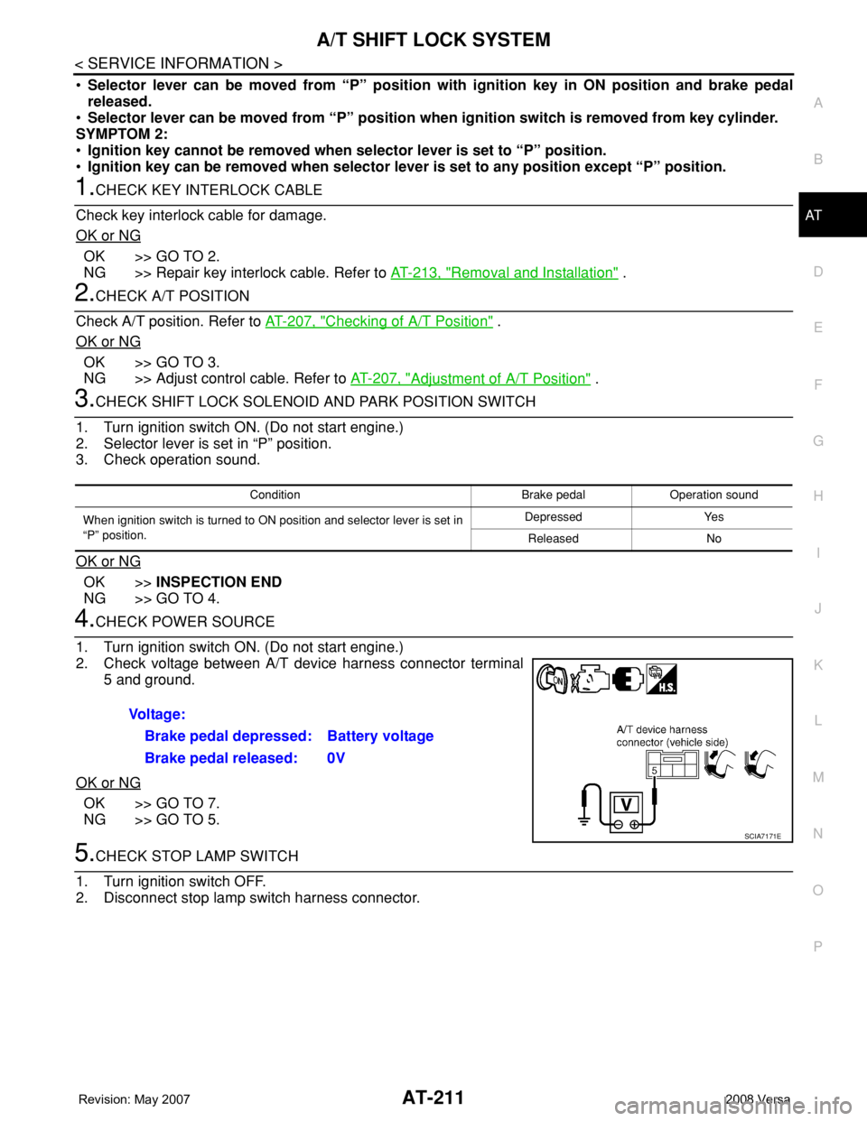
2. Check voltage between A/T device harness connector terminal
5 and ground.
OK or NG
OK >> GO TO 7.
NG >> GO TO 5.
5.CHECK STOP LAMP SWITCH
1. Turn ignition switch OFF.
2. Disconnect stop lamp switch harness connector.
Condition Brake pedal Operation sound
When ignition switch is turned to ON position and selector lever is set in
“P” position.Depressed Yes
Released No
Voltage:
Brake pedal depressed: Battery voltage
Brake pedal released: 0V
SCIA7171E
Page 228 of 2771
AT-216
< SERVICE INFORMATION >
ON-VEHICLE SERVICE
ON-VEHICLE SERVICE
Control Valve Assembly and AccumulatorsINFOID:0000000001703366
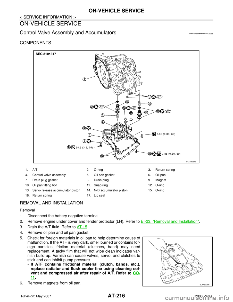
COMPONENTS
REMOVAL AND INSTALLATION
Removal
1. Disconnect the battery negative terminal.
2. Remove engine under cover and fender protector (LH). Refer to EI-23, "
Removal and Installation".
3. Drain the A/T fluid. Refer to AT- 1 5
.
4. Remove oil pan and oil pan gasket.
5. Check for foreign materials in oil pan to help determine cause of
malfunction. If the ATF is very dark, smell burned or contains for-
eign particles, friction material (clutches, band) may need
replacement. A tacky film that will not wipe clean indicates var-
nish build up. Varnish can cause valves, servo, and clutches to
stick and can inhibit pump pressure.
•If ATF contains frictional material (clutch, bands, etc.),
replace radiator and flush cooler line using cleaning sol-
vent and compressed air after repair of A/T. Refer to CO-
11.
6. Remove magnets from oil pan.
1. A/T 2. O-ring 3. Return spring
4. Control valve assembly 5. Oil pan gasket 6. Oil pan
7. Drain plug gasket 8. Drain plug 9. Magnet
10. Oil pan fitting bolt 11. Snap ring 12. O-ring
13. Servo release accumulator piston 14. N-D accumulator piston 15. O-ring
16. Return spring 17. Lip seal
SCIA8024E
SCIA8025E
Page 238 of 2771
AT-226
< SERVICE INFORMATION >
TRANSAXLE ASSEMBLY
TRANSAXLE ASSEMBLY
Removal and InstallationINFOID:0000000001703372
COMPONENTS
REMOVAL
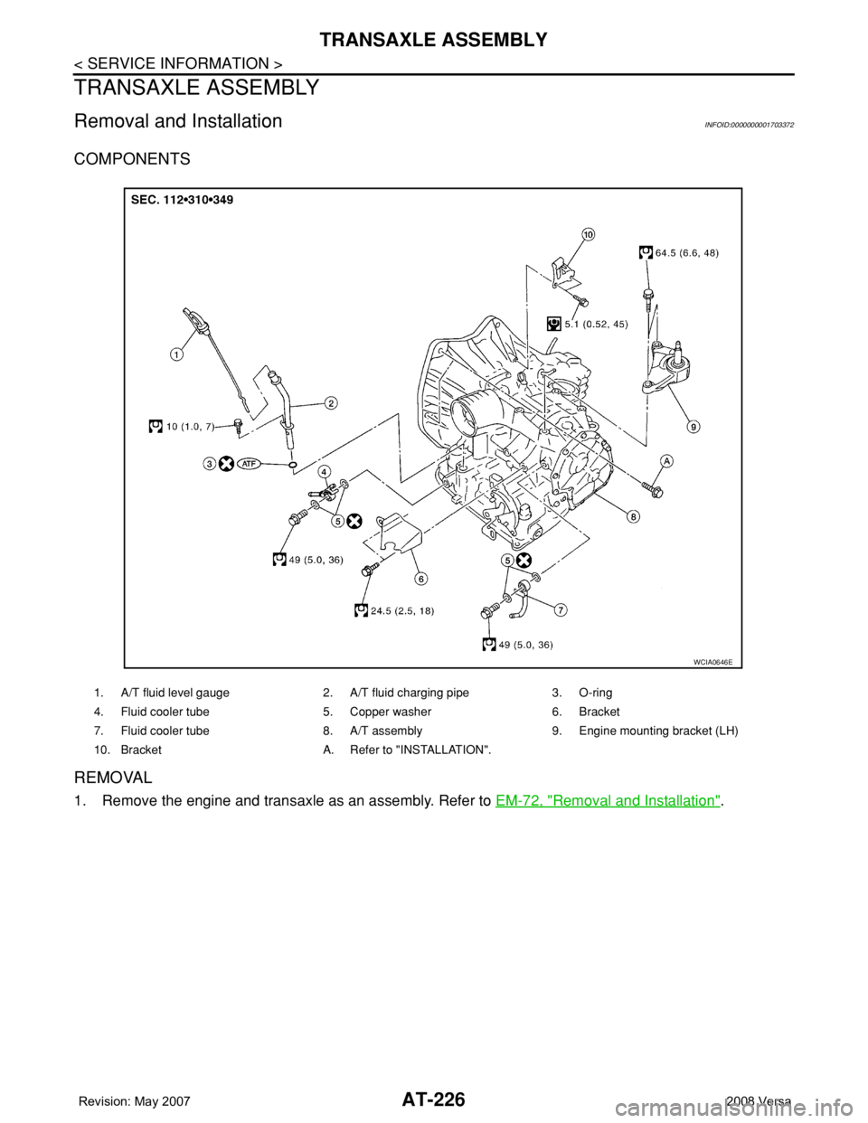
1. Remove the engine and transaxle as an assembly. Refer to EM-72, "Removal and Installation".
1. A/T fluid level gauge 2. A/T fluid charging pipe 3. O-ring
4. Fluid cooler tube 5. Copper washer 6. Bracket
7. Fluid cooler tube 8. A/T assembly 9. Engine mounting bracket (LH)
10. Bracket A. Refer to "INSTALLATION".
WCIA0646E
Page 239 of 2771
TRANSAXLE ASSEMBLY
AT-227
< SERVICE INFORMATION >
D
E
F
G
H
I
J
K
L
MA
B
AT
N
O
P
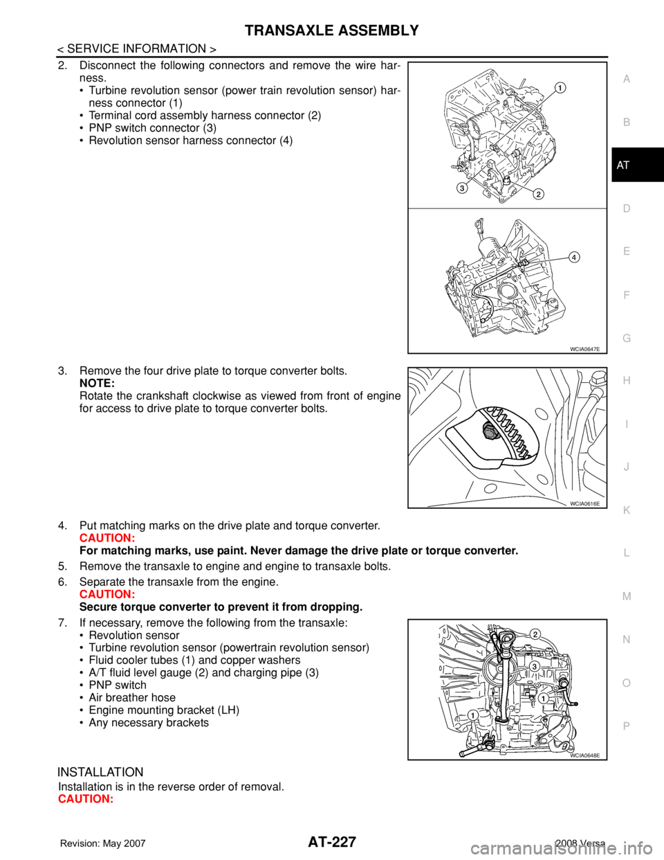
2. Disconnect the following connectors and remove the wire har-
ness.
• Turbine revolution sensor (power train revolution sensor) har-
ness connector (1)
• Terminal cord assembly harness connector (2)
• PNP switch connector (3)
• Revolution sensor harness connector (4)
3. Remove the four drive plate to torque converter bolts.
NOTE:
Rotate the crankshaft clockwise as viewed from front of engine
for access to drive plate to torque converter bolts.
4. Put matching marks on the drive plate and torque converter.
CAUTION:
For matching marks, use paint. Never damage the drive plate or torque converter.
5. Remove the transaxle to engine and engine to transaxle bolts.
6. Separate the transaxle from the engine.
CAUTION:
Secure torque converter to prevent it from dropping.
7. If necessary, remove the following from the transaxle:
• Revolution sensor
• Turbine revolution sensor (powertrain revolution sensor)
• Fluid cooler tubes (1) and copper washers
• A/T fluid level gauge (2) and charging pipe (3)
• PNP switch
• Air breather hose
• Engine mounting bracket (LH)
• Any necessary brackets
INSTALLATION
Installation is in the reverse order of removal.
CAUTION:
WCIA0647E
WCIA0616E
WCIA0648E