2008 NISSAN LATIO ignition
[x] Cancel search: ignitionPage 2574 of 2771

SEAT BELTS
SB-3
< ON-VEHICLE REPAIR >
C
D
E
F
G
I
J
K
L
MA
B
SB
N
O
P
ON-VEHICLE REPAIR
SEAT BELTS
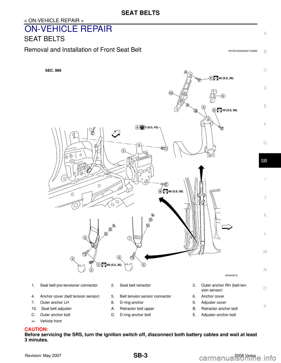
Removal and Installation of Front Seat BeltINFOID:0000000001703899
CAUTION:
Before servicing the SRS, turn the ignition switch off, disconnect both battery cables and wait at least
3 minutes.
1. Seat belt pre-tensioner connector 2. Seat belt retractor 3. Outer anchor RH (belt ten-
sion sensor)
4. Anchor cover (belt tension sensor) 5. Belt tension sensor connector 6. Anchor cover
7. Outer anchor LH 8. D-ring anchor 9. Adjuster cover
10. Seat belt adjuster A. Retractor bolt upper B. Retractor anchor bolt
C. Outer anchor bolt D. D-ring anchor bolt E. Adjuster anchor bolt
⇐Vehicle front
WHIA0361E
Page 2579 of 2771

SB-8
< ON-VEHICLE REPAIR >
SEAT BELTS
• The seat belt was damaged in an accident. (i.e. torn webbing, bent retractor or guide, etc.)
• The seat belt attaching point was damaged in an accident. Inspect the seat belt attaching area for damage
or distortion and repair as necessary before installing a new seat belt assembly.
• Anchor bolts are deformed or worn out.
• The seat belt pre-tensioner should be replaced even if the seat belts are not in use during a frontal collision
in which the air bags are deployed.
PRELIMINARY CHECKS
1. Check the seat belt warning lamp/chime for proper operation as follows:
a. Switch ignition ON. The seat belt warning lamp should illuminate. Also, the seat belt warning chime should
sound for about seven seconds.
b. Fasten driver's seat belt. The seat belt warning lamp should go out and the chime (if sounding) should
stop.
2. If the air bag warning lamp is blinking, conduct self-diagnosis using CONSULT-II, and air bag warning
lamp. Refer to SRS-18, "
SRS Operation Check".
3. Check that the seat belt retractor, seat belt anchor and buckle bolts are securely attached.
4. Check the shoulder seat belt guide and shoulder belt height adjuster for front seats. Make sure guide
swivels freely and that webbing lays flat and does not bind in guide. Make sure height adjuster operates
properly and holds securely.
5. Check retractor operation:
a. Fully extend the seat belt webbing and check for twists, tears or other damage.
b. Allow the seat belt to retract. Make sure that webbing returns smoothly and completely into the retractor. If
the seat belt does not return smoothly, wipe the inside of the loops with a clean paper cloth. Dirt build-up
in the loops of the upper anchors can cause the seat belts to retract slowly.
c. Fasten the seat belt. Check the seat belt returns smoothly and completely to the retractor. If the webbing
does not return smoothly, the cause may be an accumulation of dust or dirt. Use the “SEAT BELT TAPE
SET” and perform the following steps.
Inspect the front seat belt though-anchor 1. Pull the seat belt out to a length of 500 mm (19.69 in) or more.
2. Use a clip or other device to attach the seat belt at the center pillar webbing opening.
3. Pass a thin wire though the D-ring anchor webbing opening. Hold both ends of the wire and pull taut
while moving it up and down several times along the webbing opening surface to remove matter stuck
there.
4. Any dirt that cannot be removed with the wire can be removed by cleaning the opening with a clean
cloth.
5. Apply tape at the point where the webbing contacts the though-anchor webbing opening.
NOTE:
Apply the tape so that there is no looseness or wrinkling.
6. Remove the clip attaching the seat belt and check that the webbing returns smoothly.
6. Repeat steps above as necessary to check the other seat belts.
SEAT BELT RETRACTOR ON-VEHICLE CHECK
Emergency Locking Retractors (ELR) and Automatic Locking Retractors (ALR)
NOTE:
All seat belt retractors are of the Emergency Locking Retractors (ELR) type. In an emergency (sudden stop)
the retractor will lock and prevent the webbing from extending any further. All 3-point type seat belt retractors
except the driver's seat belt also have an Automatic Locking Retractors (ALR) mode. The ALR mode (also
called child restraint mode) is used when installing child seats. The ALR mode is activated when the seat belt
is fully extended. When the webbing is then retracted partially, the ALR mode automatically locks the seat belt
in a specific position so the webbing cannot be extended any further. To cancel the ALR mode, allow the seat
belt to fully wind back into the retractor.
Check the seat belt retractors using the following test(s) to determine if a retractor assembly is operating prop-
erly.
ELR Function Stationary Check
Grasp the shoulder webbing and pull it forward quickly. The retractor should lock and prevent the belt from
extending further.
Page 2590 of 2771

SC-8
< SERVICE INFORMATION >
STARTING SYSTEM
STARTING SYSTEM
System DescriptionINFOID:0000000001704348
M/T Models
Power is supplied at all times
• to starter motor terminal B, and
• through 40A fusible link (letter h , located in the fuse and fusible link box)
• to ignition switch terminal B.
With the ignition switch in the START position, power is supplied
• from ignition switch terminal ST
• to IPDM E/R terminal 21.
With the ignition switch in the ON or START position, power is supplied
• through 10A fuse (No. 49, located in the IPDM E/R)
• to the clutch interlock switch terminal 1.
With the clutch pedal depressed, power is supplied
• through the clutch interlock switch terminal 2
• to IPDM E/R terminal 35.
Ground is supplied at all times
• to IPDM E/R terminals 39 and 59
• through body grounds E15 and E24.
If the IPDM E/R receives a starter relay request ON signal from the BCM over the CAN communication lines,
the IPDM E/R grounds the starter relay and power is supplied
• through terminal 19 of the IPDM E/R
• to terminal S of the starter motor.
The starter motor magnetic switch energizes closing the circuit between the battery and the starter motor. The
starter motor is case ground through the cylinder block. With power and ground supplied, the starter motor
operates.
A/T Models
Power is supplied at all times
• to starter motor terminal B, and
• through 40A fusible link (letter h , located in the fuse and fusible link box)
• to ignition switch terminal B.
With the ignition switch in the START position, power is supplied
• from ignition switch terminal ST
• to IPDM E/R terminal 21.
With the ignition switch in the ON or START position, power is supplied
• through 10A fuse (No. 54, located in the IPDM E/R)
• to park/neutral position (PNP) switch terminal 1.
With the selector lever in the P or N position, power is supplied
• through PNP switch terminal 2
• to IPDM E/R terminal 35.
Ground is supplied at all times
• to IPDM E/R terminals 39 and 59
• through body grounds E15 and E24.
If the IPDM E/R receives a starter relay request ON signal from the BCM over the CAN communication lines,
the IPDM E/R grounds the starter relay and power is supplied
• through terminal 19 of the IPDM E/R
• to terminal S of the starter motor.
The starter motor magnetic switch energizes closing the circuit between the battery and the starter motor. The
starter motor is case ground through the cylinder block. With power and ground supplied, the starter motor
operates.
CVT Models
Power is supplied at all times
• to starter motor terminal B, and
• through 40A fusible link (letter h , located in the fuse and fusible link box)
• to ignition switch terminal B.
With the ignition switch in the START position, power is supplied
• from ignition switch terminal ST
Page 2599 of 2771

STARTING SYSTEM
SC-17
< SERVICE INFORMATION >
C
D
E
F
G
H
I
J
L
MA
B
SC
N
O
P
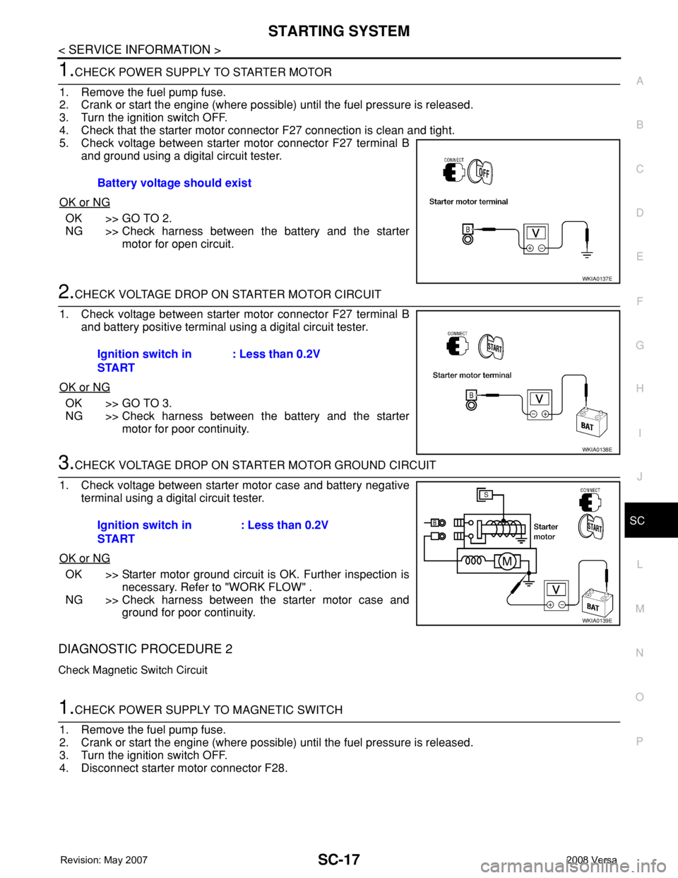
1.CHECK POWER SUPPLY TO STARTER MOTOR
1. Remove the fuel pump fuse.
2. Crank or start the engine (where possible) until the fuel pressure is released.
3. Turn the ignition switch OFF.
4. Check that the starter motor connector F27 connection is clean and tight.
5. Check voltage between starter motor connector F27 terminal B
and ground using a digital circuit tester.
OK or NG
OK >> GO TO 2.
NG >> Check harness between the battery and the starter
motor for open circuit.
2.CHECK VOLTAGE DROP ON STARTER MOTOR CIRCUIT
1. Check voltage between starter motor connector F27 terminal B
and battery positive terminal using a digital circuit tester.
OK or NG
OK >> GO TO 3.
NG >> Check harness between the battery and the starter
motor for poor continuity.
3.CHECK VOLTAGE DROP ON STARTER MOTOR GROUND CIRCUIT
1. Check voltage between starter motor case and battery negative
terminal using a digital circuit tester.
OK or NG
OK >> Starter motor ground circuit is OK. Further inspection is
necessary. Refer to "WORK FLOW" .
NG >> Check harness between the starter motor case and
ground for poor continuity.
DIAGNOSTIC PROCEDURE 2
Check Magnetic Switch Circuit
1.CHECK POWER SUPPLY TO MAGNETIC SWITCH
1. Remove the fuel pump fuse.
2. Crank or start the engine (where possible) until the fuel pressure is released.
3. Turn the ignition switch OFF.
4. Disconnect starter motor connector F28.Battery voltage should exist
WKIA0137E
Ignition switch in
START: Less than 0.2V
WKIA0138E
Ignition switch in
START: Less than 0.2V
WKIA0139E
Page 2600 of 2771

SC-18
< SERVICE INFORMATION >
STARTING SYSTEM
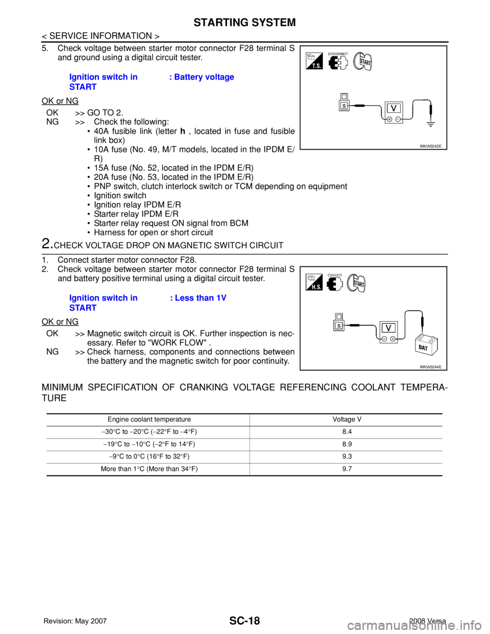
5. Check voltage between starter motor connector F28 terminal S
and ground using a digital circuit tester.
OK or NG
OK >> GO TO 2.
NG >> Check the following:
• 40A fusible link (letter h , located in fuse and fusible
link box)
• 10A fuse (No. 49, M/T models, located in the IPDM E/
R)
• 15A fuse (No. 52, located in the IPDM E/R)
• 20A fuse (No. 53, located in the IPDM E/R)
• PNP switch, clutch interlock switch or TCM depending on equipment
• Ignition switch
• Ignition relay IPDM E/R
• Starter relay IPDM E/R
• Starter relay request ON signal from BCM
• Harness for open or short circuit
2.CHECK VOLTAGE DROP ON MAGNETIC SWITCH CIRCUIT
1. Connect starter motor connector F28.
2. Check voltage between starter motor connector F28 terminal S
and battery positive terminal using a digital circuit tester.
OK or NG
OK >> Magnetic switch circuit is OK. Further inspection is nec-
essary. Refer to "WORK FLOW" .
NG >> Check harness, components and connections between
the battery and the magnetic switch for poor continuity.
MINIMUM SPECIFICATION OF CRANKING VOLTAGE REFERENCING COOLANT TEMPERA-
TURE
Ignition switch in
START: Battery voltage
WKIA5243E
Ignition switch in
START: Less than 1V
WKIA5244E
Engine coolant temperature Voltage V
−30°C to −20°C (−22°F to −4°F) 8.4
−19°C to −10°C (−2°F to 14°F) 8.9
−9°C to 0°C (16°F to 32°F) 9.3
More than 1°C (More than 34°F) 9.7
Page 2602 of 2771

SC-20
< SERVICE INFORMATION >
CHARGING SYSTEM
CHARGING SYSTEM
System DescriptionINFOID:0000000001704352
The generator provides DC voltage to operate the vehicle's electrical system and to keep the battery charged.
The voltage output is controlled by the IC regulator.
Power is supplied at all times to generator terminal 3 through
• 10A fuse (No. 29, located in the fuse and fusible link box).
Power is supplied through terminal 1 to charge the battery and operate the vehicle's electrical system. Output
voltage is monitored at terminal 3 by the IC regulator. The charging circuit is protected by the 120A fusible link
[letter a , located in the fusible link box (battery)].
Ground is supplied
• to generator terminal 5
• through body ground F5, and
• through the generator case to the cylinder block
With the ignition switch in the ON or START position, power is supplied
• through 10A fuse [No. 3, located in the fuse block (J/B)]
• to combination meter terminal 28 for the charge warning lamp.
The IC regulator controls ground to terminal 38 of the combination meter through terminal 2 of the generator.
When the ignition is turned on and power becomes available at terminal 2, this "wakes up" the regulator. The
regulator monitors charge output and grounds terminal 2 or leaves it open depending on charge output. With
power and ground supplied, the charge warning lamp will illuminate. When the generator is providing sufficient
voltage, the ground is opened and the charge warning lamp will go off.
If the charge warning lamp illuminates with the engine running, a malfunction is indicated.
Page 2620 of 2771

SE-12
< SERVICE INFORMATION >
FRONT SEAT
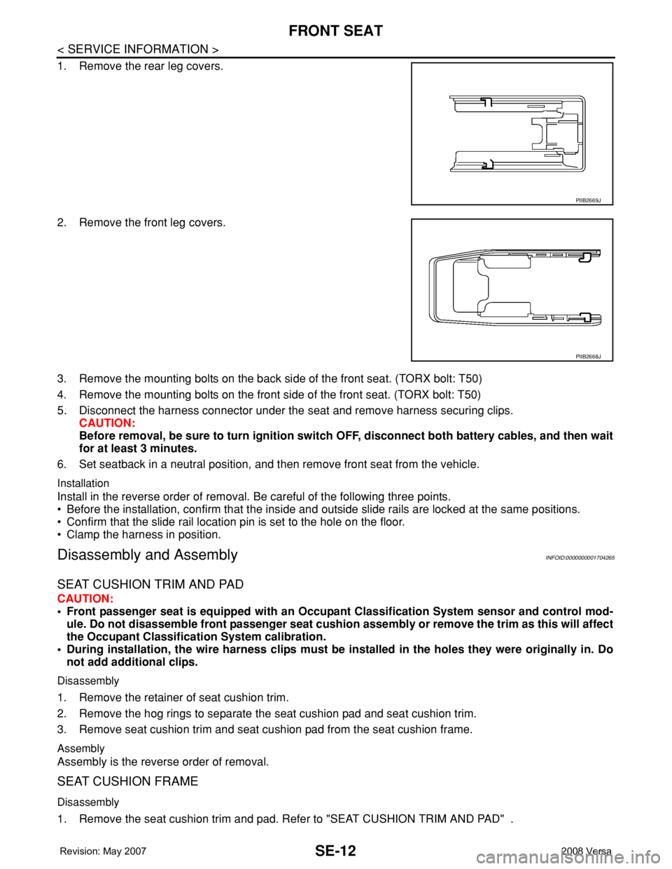
1. Remove the rear leg covers.
2. Remove the front leg covers.
3. Remove the mounting bolts on the back side of the front seat. (TORX bolt: T50)
4. Remove the mounting bolts on the front side of the front seat. (TORX bolt: T50)
5. Disconnect the harness connector under the seat and remove harness securing clips.
CAUTION:
Before removal, be sure to turn ignition switch OFF, disconnect both battery cables, and then wait
for at least 3 minutes.
6. Set seatback in a neutral position, and then remove front seat from the vehicle.
Installation
Install in the reverse order of removal. Be careful of the following three points.
• Before the installation, confirm that the inside and outside slide rails are locked at the same positions.
• Confirm that the slide rail location pin is set to the hole on the floor.
• Clamp the harness in position.
Disassembly and AssemblyINFOID:0000000001704265
SEAT CUSHION TRIM AND PAD
CAUTION:
• Front passenger seat is equipped with an Occupant Classification System sensor and control mod-
ule. Do not disassemble front passenger seat cushion assembly or remove the trim as this will affect
the Occupant Classification System calibration.
• During installation, the wire harness clips must be installed in the holes they were originally in. Do
not add additional clips.
Disassembly
1. Remove the retainer of seat cushion trim.
2. Remove the hog rings to separate the seat cushion pad and seat cushion trim.
3. Remove seat cushion trim and seat cushion pad from the seat cushion frame.
Assembly
Assembly is the reverse order of removal.
SEAT CUSHION FRAME
Disassembly
1. Remove the seat cushion trim and pad. Refer to "SEAT CUSHION TRIM AND PAD" .
PIIB2669J
PIIB2668J
Page 2636 of 2771

SRS-2
< PRECAUTION >
PRECAUTIONS
PRECAUTION
PRECAUTIONS
Precaution for Supplemental Restraint System (SRS) "AIR BAG" and "SEAT BELT
PRE-TENSIONER"
INFOID:0000000001703904
The Supplemental Restraint System such as “AIR BAG” and “SEAT BELT PRE-TENSIONER”, used along
with a front seat belt, helps to reduce the risk or severity of injury to the driver and front passenger for certain
types of collision. This system includes seat belt switch inputs and dual stage front air bag modules. The SRS
system uses the seat belt switches to determine the front air bag deployment, and may only deploy one front
air bag, depending on the severity of a collision and whether the front occupants are belted or unbelted.
Information necessary to service the system safely is included in the SR and SB section of this Service Man-
ual.
WARNING:
• To avoid rendering the SRS inoperative, which could increase the risk of personal injury or death in
the event of a collision which would result in air bag inflation, all maintenance must be performed by
an authorized NISSAN/INFINITI dealer.
• Improper maintenance, including incorrect removal and installation of the SRS, can lead to personal
injury caused by unintentional activation of the system. For removal of Spiral Cable and Air Bag
Module, see the SR section.
• Do not use electrical test equipment on any circuit related to the SRS unless instructed to in this
Service Manual. SRS wiring harnesses can be identified by yellow and/or orange harnesses or har-
ness connectors.
Precaution for SRS "AIR BAG" and "SEAT BELT PRE-TENSIONER" Service
INFOID:0000000001703905
• Do not use electrical test equipment to check SRS circuits unless instructed to in this Service Manual.
• Before servicing the SRS, turn ignition switch OFF, disconnect both battery cables and wait at least 3 min-
utes.
For approximately 3 minutes after the cables are removed, it is still possible for the air bag and seat belt pre-
tensioner to deploy. Therefore, do not work on any SRS connectors or wires until at least 3 minutes have
passed.
• The air bag diagnosis sensor unit must always be installed with the arrow mark “⇐” pointing toward the front
of the vehicle for proper operation. Also check air bag diagnosis sensor unit for cracks, deformities or rust
before installation and replace as required.
• The spiral cable must be aligned with the neutral position since its rotations are limited. Do not attempt to
turn steering wheel or column after removal of steering gear.
• Handle air bag module carefully. Always place driver and front passenger air bag modules with the pad side
facing upward and seat mounted front side air bag module standing with the stud bolt side facing down.
• Conduct self-diagnosis to check entire SRS for proper function after replacing any components.
• After air bag inflates, the front instrument panel assembly should be replaced if damaged.
• Do not reuse center pillar upper garnish if removed.
Occupant Classification System PrecautionINFOID:0000000001703906
Replace control unit and passenger front seat cushion as an assembly.