Page 2379 of 2771
TROUBLE DIAGNOSIS
MTC-41
< SERVICE INFORMATION >
C
D
E
F
G
H
I
K
L
MA
B
MTC
N
O
P
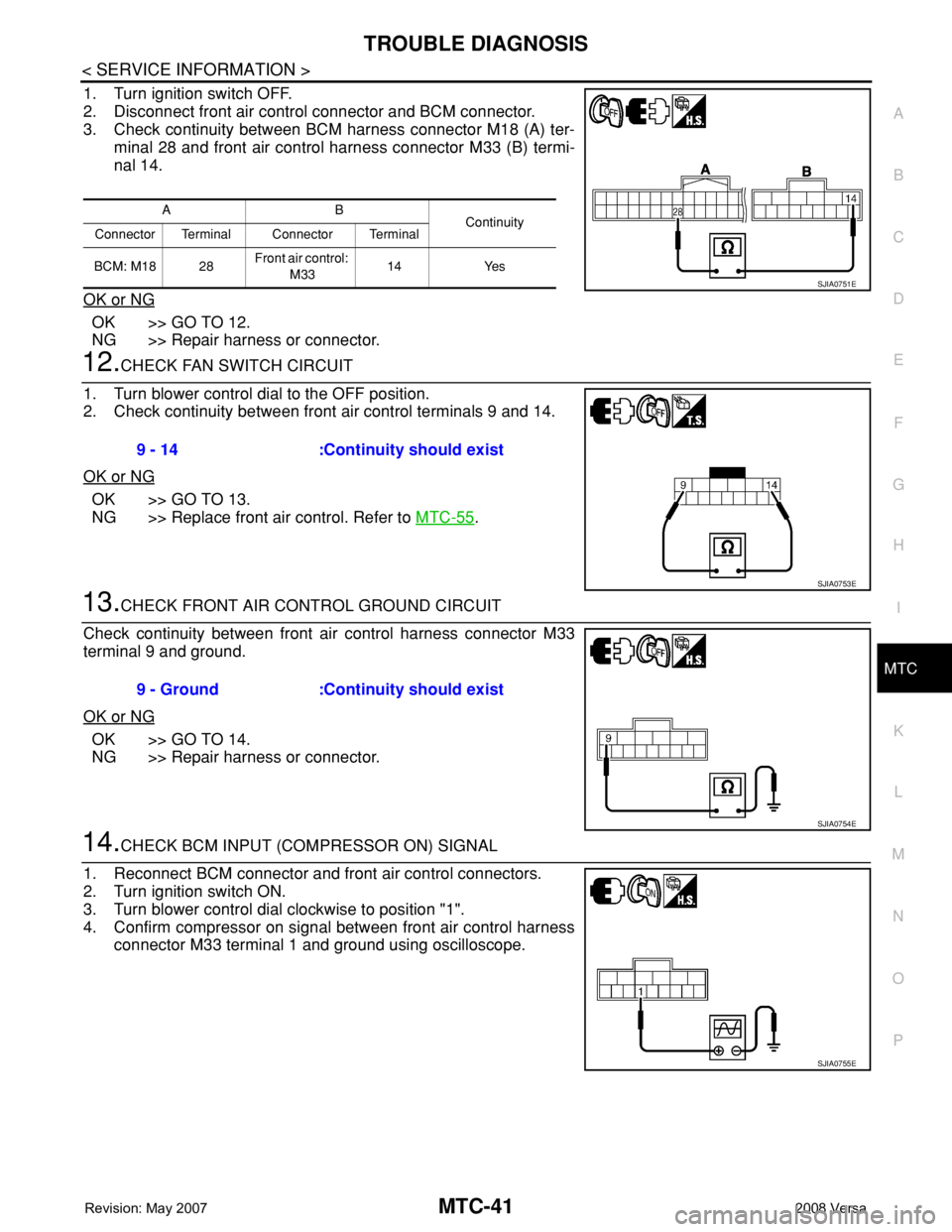
1. Turn ignition switch OFF.
2. Disconnect front air control connector and BCM connector.
3. Check continuity between BCM harness connector M18 (A) ter-
minal 28 and front air control harness connector M33 (B) termi-
nal 14.
OK or NG
OK >> GO TO 12.
NG >> Repair harness or connector.
12.CHECK FAN SWITCH CIRCUIT
1. Turn blower control dial to the OFF position.
2. Check continuity between front air control terminals 9 and 14.
OK or NG
OK >> GO TO 13.
NG >> Replace front air control. Refer to MTC-55
.
13.CHECK FRONT AIR CONTROL GROUND CIRCUIT
Check continuity between front air control harness connector M33
terminal 9 and ground.
OK or NG
OK >> GO TO 14.
NG >> Repair harness or connector.
14.CHECK BCM INPUT (COMPRESSOR ON) SIGNAL
1. Reconnect BCM connector and front air control connectors.
2. Turn ignition switch ON.
3. Turn blower control dial clockwise to position "1".
4. Confirm compressor on signal between front air control harness
connector M33 terminal 1 and ground using oscilloscope.
AB
Continuity
Connector Terminal Connector Terminal
BCM: M18 28Front air control:
M3314 Yes
SJIA0751E
9 - 14 :Continuity should exist
SJIA0753E
9 - Ground :Continuity should exist
SJIA0754E
SJIA0755E
Page 2380 of 2771
MTC-42
< SERVICE INFORMATION >
TROUBLE DIAGNOSIS
OK or NG
OK >> GO TO 15.
NG >> GO TO 17.
15.CHECK A/C SWITCH CIRCUIT
1. Turn ignition switch OFF.
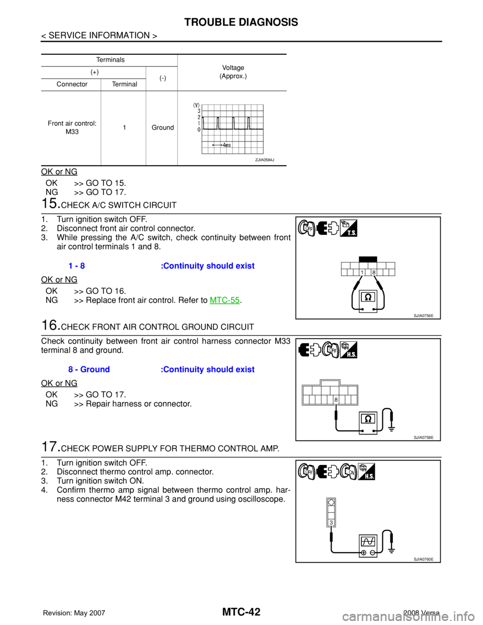
2. Disconnect front air control connector.
3. While pressing the A/C switch, check continuity between front
air control terminals 1 and 8.
OK or NG
OK >> GO TO 16.
NG >> Replace front air control. Refer to MTC-55
.
16.CHECK FRONT AIR CONTROL GROUND CIRCUIT
Check continuity between front air control harness connector M33
terminal 8 and ground.
OK or NG
OK >> GO TO 17.
NG >> Repair harness or connector.
17.CHECK POWER SUPPLY FOR THERMO CONTROL AMP.
1. Turn ignition switch OFF.
2. Disconnect thermo control amp. connector.
3. Turn ignition switch ON.
4. Confirm thermo amp signal between thermo control amp. har-
ness connector M42 terminal 3 and ground using oscilloscope.
Te r m i n a l s
Vo l ta g e
(Approx.) (+)
(-)
Connector Terminal
Front air control:
M331Ground
ZJIA0584J
1 - 8 :Continuity should exist
SJIA0756E
8 - Ground :Continuity should exist
SJIA0758E
SJIA0760E
Page 2381 of 2771
TROUBLE DIAGNOSIS
MTC-43
< SERVICE INFORMATION >
C
D
E
F
G
H
I
K
L
MA
B
MTC
N
O
P
OK or NG
OK >> • GO TO 18 (with CVT).
• GO TO 19 (without CVT).
NG >> GO TO 21.
18.CHECK THERMO CONTROL AMP. GROUND CIRCUIT
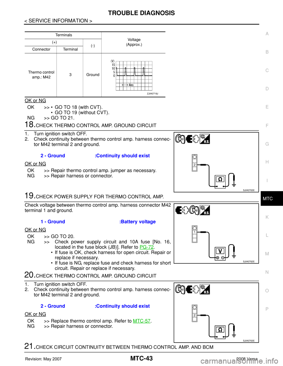
1. Turn ignition switch OFF.
2. Check continuity between thermo control amp. harness connec-
tor M42 terminal 2 and ground.
OK or NG
OK >> Repair thermo control amp. jumper as necessary.
NG >> Repair harness or connector.
19.CHECK POWER SUPPLY FOR THERMO CONTROL AMP.
Check voltage between thermo control amp. harness connector M42
terminal 1 and ground.
OK or NG
OK >> GO TO 20.
NG >> Check power supply circuit and 10A fuse [No. 16,
located in the fuse block (JB)]. Refer to PG-72
.
• If fuse is OK, check harness for open circuit. Repair or
replace if necessary.
• If fuse is NG, replace fuse and check harness for short
circuit. Repair or replace if necessary.
20.CHECK THERMO CONTROL AMP. GROUND CIRCUIT
1. Turn ignition switch OFF.
2. Check continuity between thermo control amp. harness connec-
tor M42 terminal 2 and ground.
OK or NG
OK >> Replace thermo control amp. Refer to MTC-57.
NG >> Repair harness or connector.
21.CHECK CIRCUIT CONTINUITY BETWEEN THERMO CONTROL AMP. AND BCM
Te r m i n a l s
Vol tag e
(Approx.) (+)
(-)
Connector Terminal
Thermo control
amp.: M423Ground
ZJIA0719J
2 - Ground :Continuity should exist
SJIA0763E
1 - Ground :Battery voltage
SJIA0762E
2 - Ground :Continuity should exist
SJIA0763E
Page 2382 of 2771
MTC-44
< SERVICE INFORMATION >
TROUBLE DIAGNOSIS
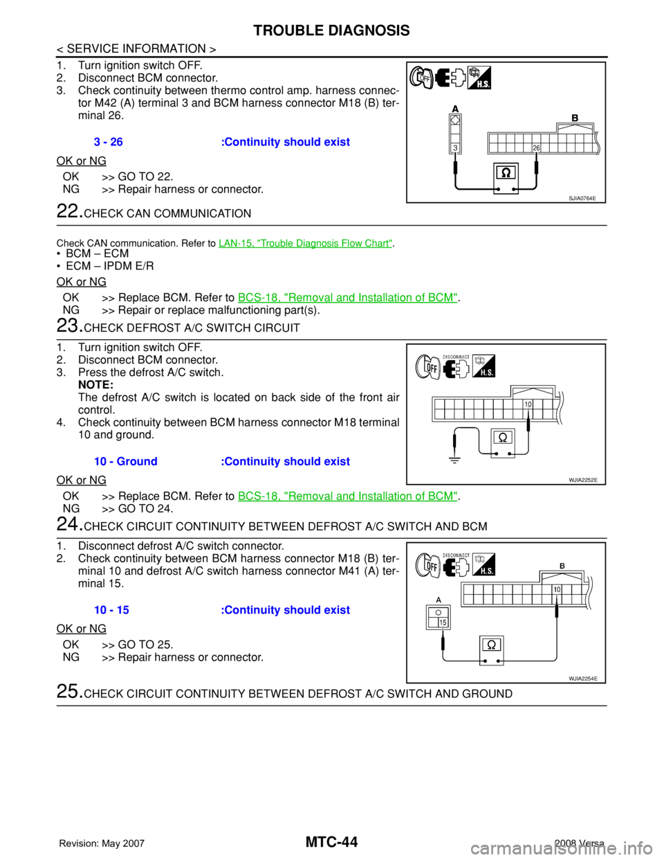
1. Turn ignition switch OFF.
2. Disconnect BCM connector.
3. Check continuity between thermo control amp. harness connec-
tor M42 (A) terminal 3 and BCM harness connector M18 (B) ter-
minal 26.
OK or NG
OK >> GO TO 22.
NG >> Repair harness or connector.
22.CHECK CAN COMMUNICATION
Check CAN communication. Refer to LAN-15, "Trouble Diagnosis Flow Chart".
•BCM – ECM
• ECM – IPDM E/R
OK or NG
OK >> Replace BCM. Refer to BCS-18, "Removal and Installation of BCM".
NG >> Repair or replace malfunctioning part(s).
23.CHECK DEFROST A/C SWITCH CIRCUIT
1. Turn ignition switch OFF.
2. Disconnect BCM connector.
3. Press the defrost A/C switch.
NOTE:
The defrost A/C switch is located on back side of the front air
control.
4. Check continuity between BCM harness connector M18 terminal
10 and ground.
OK or NG
OK >> Replace BCM. Refer to BCS-18, "Removal and Installation of BCM".
NG >> GO TO 24.
24.CHECK CIRCUIT CONTINUITY BETWEEN DEFROST A/C SWITCH AND BCM
1. Disconnect defrost A/C switch connector.
2. Check continuity between BCM harness connector M18 (B) ter-
minal 10 and defrost A/C switch harness connector M41 (A) ter-
minal 15.
OK or NG
OK >> GO TO 25.
NG >> Repair harness or connector.
25.CHECK CIRCUIT CONTINUITY BETWEEN DEFROST A/C SWITCH AND GROUND 3 - 26 :Continuity should exist
SJIA0764E
10 - Ground :Continuity should exist
WJIA2252E
10 - 15 :Continuity should exist
WJIA2254E
Page 2426 of 2771
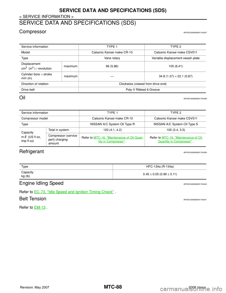
MTC-88
< SERVICE INFORMATION >
SERVICE DATA AND SPECIFICATIONS (SDS)
SERVICE DATA AND SPECIFICATIONS (SDS)
CompressorINFOID:0000000001704337
OilINFOID:0000000001704338
RefrigerantINFOID:0000000001704339
Engine Idling SpeedINFOID:0000000001704340
Refer to EC-73, "Idle Speed and Ignition Timing Check" .
Belt TensionINFOID:0000000001704341
Refer to EM-13 .
Service information TYPE 1 TYPE 2
Model Calsonic Kansei make CR-10 Calsonic Kansei make CSV511
Type Vane rotary Variable displacement swash plate
Displacement
cm
3 (in3 ) / revolutionmaximum 96 (5.86) 105 (6.41)
Cylinder bore × stroke
mm (in)maximum — 34.8 (1.37) × 22.1 (0.87)
Direction of rotation Clockwise (viewed from drive end)
Drive belt Poly-V Ribbed 6-Groove
Service information TYPE 1 TYPE 2
Compressor model Calsonic Kansei make CR-10 Calsonic Kansei make CSV511
Type NISSAN A/C System Oil Type R NISSAN A/C System Oil Type S
Capacity
m (US fl oz,
lmp fl oz)Total in system 120 (4.1, 4.2) 100 (3.4, 3.5)
Compressor (service
part) charging
amountRefer to MTC-16, "
Maintenance of Oil Quan-
tity in Compressor" .Refer to MTC-16, "
Maintenance of Oil
Quantity in Compressor" .
Ty p eHFC-134a (R-134a)
Capacity
kg (lb)0.45 ± 0.05 (0.99 ± 0.11)
Page 2434 of 2771

PG-1
ELECTRICAL
C
D
E
F
G
H
I
J
L
M
SECTION PG
A
B
PG
N
O
P
CONTENTS
POWER SUPPLY, GROUND & CIRCUIT ELEMENTS
SERVICE INFORMATION ............................2
PRECAUTIONS ...................................................2
Precaution for Supplemental Restraint System
(SRS) "AIR BAG" and "SEAT BELT PRE-TEN-
SIONER" ...................................................................
2
POWER SUPPLY ROUTING CIRCUIT ...............3
Schematic .................................................................3
Wiring Diagram - POWER - ......................................5
Fuse ........................................................................15
Fusible Link .............................................................15
Circuit Breaker (Built Into BCM) ..............................15
Circuit Breaker ........................................................15
IPDM E/R (INTELLIGENT POWER DISTRI-
BUTION MODULE ENGINE ROOM) .................
16
System Description .................................................16
CAN Communication System Description ...............17
Function of Detecting Ignition Relay Malfunction ....17
CONSULT-III Function (IPDM E/R) .........................17
Auto Active Test ......................................................19
IPDM E/R Terminal Arrangement ...........................22
Terminal and Reference Value for IPDM E/R .........23
IPDM E/R Power/Ground Circuit Inspection ...........25
Inspection with CONSULT-III (Self-Diagnosis) .......26
Removal and Installation of IPDM E/R ....................26
GROUND CIRCUIT ...........................................28
Ground Distribution ..................................................28
HARNESS .........................................................37
Harness Layout .......................................................37
Wiring Diagram Codes (Cell Codes) .......................58
ELECTRICAL UNITS LOCATION ....................61
Electrical Units Location ..........................................61
HARNESS CONNECTOR .................................65
Description ...............................................................65
ELECTRICAL UNITS ........................................68
Terminal Arrangement .............................................68
STANDARDIZED RELAY .................................69
Description ...............................................................69
SUPER MULTIPLE JUNCTION (SMJ) .............71
Terminal Arrangement .............................................71
FUSE BLOCK-JUNCTION BOX (J/B) ..............72
Terminal Arrangement .............................................72
FUSE AND FUSIBLE LINK BOX ......................73
Terminal Arrangement .............................................73
Page 2438 of 2771
POWER SUPPLY ROUTING CIRCUIT
PG-5
< SERVICE INFORMATION >
C
D
E
F
G
H
I
J
L
MA
B
PG
N
O
P
Wiring Diagram - POWER -INFOID:0000000001704692
BATTERY POWER SUPPLY — IGNITION SWITCH IN ANY POSITION
AWMWA0065G
Page 2443 of 2771
PG-10
< SERVICE INFORMATION >
POWER SUPPLY ROUTING CIRCUIT
ACCESSORY POWER SUPPLY — IGNITION SWITCH IN ACC AND/OR ON
LKWA0377E