Page 891 of 2771

CVT-52
< SERVICE INFORMATION >
TROUBLE DIAGNOSIS
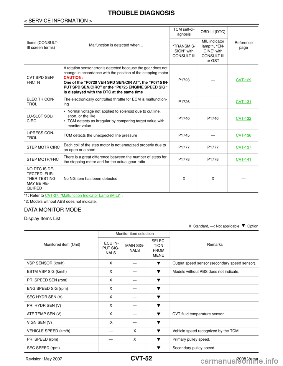
*1: Refer to CVT-27, "Malfunction Indicator Lamp (MIL)" .
*2: Models without ABS does not indicate.
DATA MONITOR MODE
Display Items List
X: Standard, —: Not applicable, : Option
CVT SPD SEN/
FNCTNA rotation sensor error is detected because the gear does not
change in accordance with the position of the stepping motor
CAUTION:
One of the “P0720 VEH SPD SEN/CIR AT”, the “P0715 IN-
PUT SPD SEN/CIRC” or the “P0725 ENGINE SPEED SIG“
is displayed with the DTC at the same timeP1723 —CVT-129
ELEC TH CON-
TROLThe electronically controlled throttle for ECM is malfunction-
ingP1726 —CVT-131
LU-SLCT SOL/
CIRC• Normal voltage not applied to solenoid due to cut line,
short, or the like
• TCM detects as irregular by comparing target value with
monitor valueP1740 P1740CVT-132
L/PRESS CON-
TROLTCM detects the unexpected line pressure P1745 —CVT-136
STEP MOTR CIRCEach coil of the step motor is not energized properly due to
an open or a shortP1777 P1777CVT-137
STEP MOTR/FNCThere is a great difference between the number of steps for
the stepping motor and for the actual gear ratioP1778 P1778CVT-141
NO DTC IS DE-
TECTED: FUR-
THER TESTING
MAY BE RE-
QUIREDNo NG item has been detected X X — Items (CONSULT-
III screen terms)Malfunction is detected when...TCM self-di-
agnosisOBD-III (DTC)
Reference
page “TRANSMIS-
SION” with
CONSULT-IIIMIL indicator
lamp*1, “EN-
GINE” with
CONSULT-III
or GST
Monitored item (Unit)Monitor item selection
Remarks ECU IN-
PUT SIG-
NALSMAIN SIG-
NALSSELEC-
TION
FROM
MENU
VSP SENSOR (km/h) X — Output speed sensor (secondary speed sensor).
ESTM VSP SIG (km/h) X — Models without ABS does not indicate.
PRI SPEED SEN (rpm) X —
ENG SPEED SIG (rpm) X —
SEC HYDR SEN (V) X —
PRI HYDR SEN (V) X —
ATF TEMP SEN (V) X — CVT fluid temperature sensor
VIGN SEN (V) X —
VEHICLE SPEED (km/h) — X Vehicle speed recognized by the TCM.
PRI SPEED (rpm) — X Primary pulley speed.
SEC SPEED (rpm) — — Secondary pulley speed.
Page 892 of 2771

TROUBLE DIAGNOSIS
CVT-53
< SERVICE INFORMATION >
D
E
F
G
H
I
J
K
L
MA
B
CVT
N
O
P
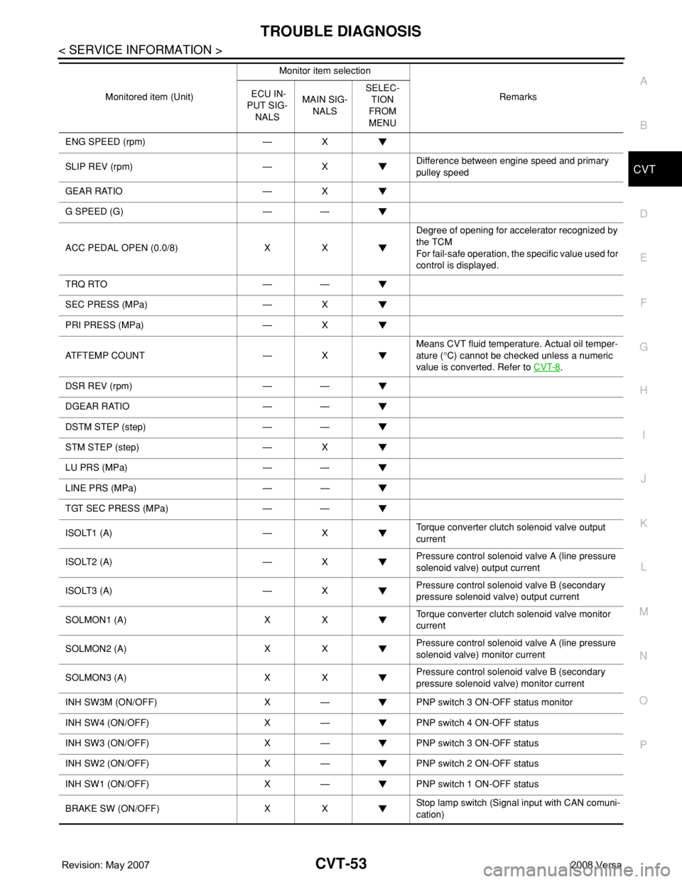
ENG SPEED (rpm) — X
SLIP REV (rpm) — XDifference between engine speed and primary
pulley speed
GEAR RATIO — X
G SPEED (G) — —
ACC PEDAL OPEN (0.0/8) X XDegree of opening for accelerator recognized by
the TCM
For fail-safe operation, the specific value used for
control is displayed.
TRQ RTO — —
SEC PRESS (MPa) — X
PRI PRESS (MPa) — X
ATFTEMP COUNT — XMeans CVT fluid temperature. Actual oil temper-
ature (°C) cannot be checked unless a numeric
value is converted. Refer to CVT-8
.
DSR REV (rpm) — —
DGEAR RATIO — —
DSTM STEP (step) — —
STM STEP (step) — X
LU PRS (MPa) — —
LINE PRS (MPa) — —
TGT SEC PRESS (MPa) — —
ISOLT1 (A) — XTorque converter clutch solenoid valve output
current
ISOLT2 (A) — XPressure control solenoid valve A (line pressure
solenoid valve) output current
ISOLT3 (A) — XPressure control solenoid valve B (secondary
pressure solenoid valve) output current
SOLMON1 (A) X XTorque converter clutch solenoid valve monitor
current
SOLMON2 (A) X XPressure control solenoid valve A (line pressure
solenoid valve) monitor current
SOLMON3 (A) X XPressure control solenoid valve B (secondary
pressure solenoid valve) monitor current
INH SW3M (ON/OFF) X — PNP switch 3 ON-OFF status monitor
INH SW4 (ON/OFF) X — PNP switch 4 ON-OFF status
INH SW3 (ON/OFF) X — PNP switch 3 ON-OFF status
INH SW2 (ON/OFF) X — PNP switch 2 ON-OFF status
INH SW1 (ON/OFF) X — PNP switch 1 ON-OFF status
BRAKE SW (ON/OFF) X XStop lamp switch (Signal input with CAN comuni-
cation) Monitored item (Unit)Monitor item selection
Remarks ECU IN-
PUT SIG-
NALSMAIN SIG-
NALSSELEC-
TION
FROM
MENU
Page 893 of 2771

CVT-54
< SERVICE INFORMATION >
TROUBLE DIAGNOSIS
FULL SW (ON/OFF) X X
Signal input with CAN communications
IDLE SW (ON/OFF) X X
SPORT MODE SW (ON/OFF) X XOverdrive control switch (Signal input with CAN
comunication)
STRDWNSW (ON/OFF) X —
Not mounted but displayed. STRUPSW (ON/OFF) X —
DOWNLVR (ON/OFF) X —
UPLVR (ON/OFF) X —
NONMMODE (ON/OFF) X —
MMODE (ON/OFF) X —
INDLRNG (ON/OFF) — — “L” position indicator output
INDDRNG (ON/OFF) — — “D” position indicator output
INDNRNG (ON/OFF) — — “N” position indicator output
INDRRNG (ON/OFF) — — “R” position indicator output
INDPRNG (ON/OFF) — — “P” position indicator output
CVT LAMP (ON/OFF) — —
SPORT MODE IND (ON/OFF) — —
MMODE IND (ON/OFF) — — Not mounted but displayed.
SMCOIL D (ON/OFF) — — Step motor coil “D” energizing status
SMCOIL C (ON/OFF) — — Step motor coil “C” energizing status
SMCOIL B (ON/OFF) — — Step motor coil “B” energizing status
SMCOIL A (ON/OFF) — — Step motor coil “A” energizing status
LUSEL SOL OUT (ON/OFF) — —
REV LAMP (ON/OFF) — X
STRTR RLY OUT (ON/OFF) — — Starter relay
LUSEL SOL MON (ON/OFF) — —
STRTR RLY MON (ON/OFF) — — Starter relay
VDC ON (ON/OFF) X —
Not mounted but displayed.
TCS ON (ON/OFF) X —
ABS ON (ON/OFF) X —
ACC ON (ON/OFF) X — Not mounted but displayed.
RANGE — XIndicates position is recognized by TCM. Indi-
cates a specific value required for control when
fail-safe function is activated.
M GEAR POS — X
Voltage (V) — —Displays the value measured by the voltage
probe. Monitored item (Unit)Monitor item selection
Remarks ECU IN-
PUT SIG-
NALSMAIN SIG-
NALSSELEC-
TION
FROM
MENU
Page 894 of 2771
TROUBLE DIAGNOSIS
CVT-55
< SERVICE INFORMATION >
D
E
F
G
H
I
J
K
L
MA
B
CVT
N
O
P
Diagnosis Procedure without CONSULT-IIIINFOID:0000000001703464
OBD-II SELF-DIAGNOSTIC PROCEDURE (WITH GST)
Refer to EC-119, "Generic Scan Tool (GST) Function".
Frequency (Hz) — —
The value measured by the pulse probe is dis-
played. DUTY-HI (high) (%) — —
DUTY-LOW (low) (%) — —
PLS WIDTH-HI (ms) — —
PLS WIDTH-LOW (ms) — —Monitored item (Unit)Monitor item selection
Remarks ECU IN-
PUT SIG-
NALSMAIN SIG-
NALSSELEC-
TION
FROM
MENU
Page 895 of 2771

CVT-56
< SERVICE INFORMATION >
DTC U1000 CAN COMMUNICATION LINE
DTC U1000 CAN COMMUNICATION LINE
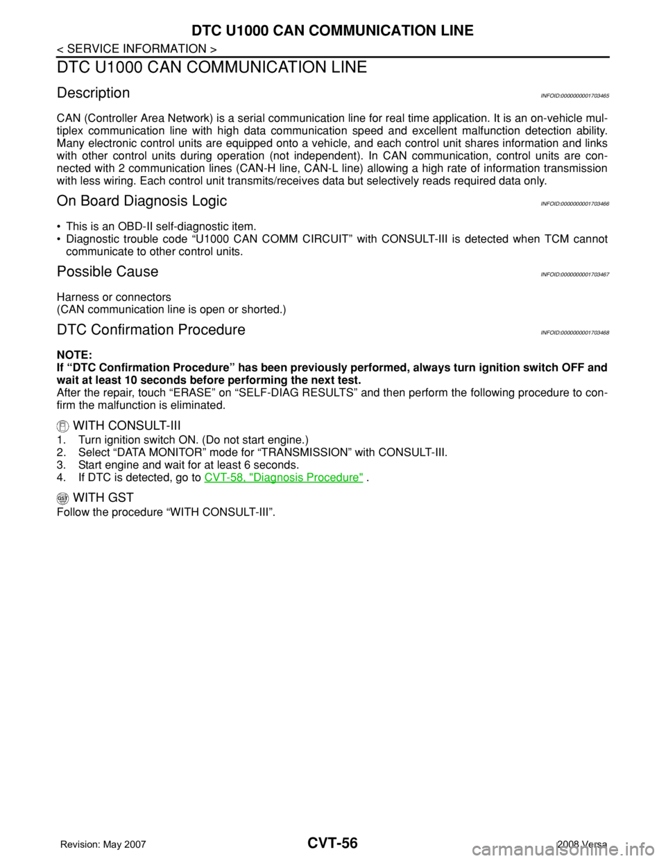
DescriptionINFOID:0000000001703465
CAN (Controller Area Network) is a serial communication line for real time application. It is an on-vehicle mul-
tiplex communication line with high data communication speed and excellent malfunction detection ability.
Many electronic control units are equipped onto a vehicle, and each control unit shares information and links
with other control units during operation (not independent). In CAN communication, control units are con-
nected with 2 communication lines (CAN-H line, CAN-L line) allowing a high rate of information transmission
with less wiring. Each control unit transmits/receives data but selectively reads required data only.
On Board Diagnosis LogicINFOID:0000000001703466
• This is an OBD-II self-diagnostic item.
• Diagnostic trouble code “U1000 CAN COMM CIRCUIT” with CONSULT-III is detected when TCM cannot
communicate to other control units.
Possible CauseINFOID:0000000001703467
Harness or connectors
(CAN communication line is open or shorted.)
DTC Confirmation ProcedureINFOID:0000000001703468
NOTE:
If “DTC Confirmation Procedure” has been previously performed, always turn ignition switch OFF and
wait at least 10 seconds before performing the next test.
After the repair, touch “ERASE” on “SELF-DIAG RESULTS” and then perform the following procedure to con-
firm the malfunction is eliminated.
WITH CONSULT-III
1. Turn ignition switch ON. (Do not start engine.)
2. Select “DATA MONITOR” mode for “TRANSMISSION” with CONSULT-III.
3. Start engine and wait for at least 6 seconds.
4. If DTC is detected, go to CVT-58, "
Diagnosis Procedure" .
WITH GST
Follow the procedure “WITH CONSULT-III”.
Page 896 of 2771
DTC U1000 CAN COMMUNICATION LINE
CVT-57
< SERVICE INFORMATION >
D
E
F
G
H
I
J
K
L
MA
B
CVT
N
O
P
Wiring Diagram - CVT - CANINFOID:0000000001703469
TCM TERMINALS AND REFERENCE VALUES
Refer to CVT-45, "TCM Terminal and Reference Value".
BCWA0668E
Page 897 of 2771
CVT-58
< SERVICE INFORMATION >
DTC U1000 CAN COMMUNICATION LINE
Diagnosis Procedure
INFOID:0000000001703470
1.CHECK CAN COMMUNICATION CIRCUIT
With CONSULT-III1. Turn ignition switch ON and start engine.
2. Select “SELF-DIAG RESULTS” mode for “TRANSMISSION” with CONSULT-III.
Is any malfunction of the
“U1000 CAN COMM CIRCUIT” indicated?
YES >> Print out CONSULT-III screen, go to LAN section. Refer to LAN-23, "CAN System Specification
Chart" .
NO >>INSPECTION END
Page 898 of 2771

DTC U1010 TRANSMISSION CONTROL MODULE (CAN)
CVT-59
< SERVICE INFORMATION >
D
E
F
G
H
I
J
K
L
MA
B
CVT
N
O
P
DTC U1010 TRANSMISSION CONTROL MODULE (CAN)
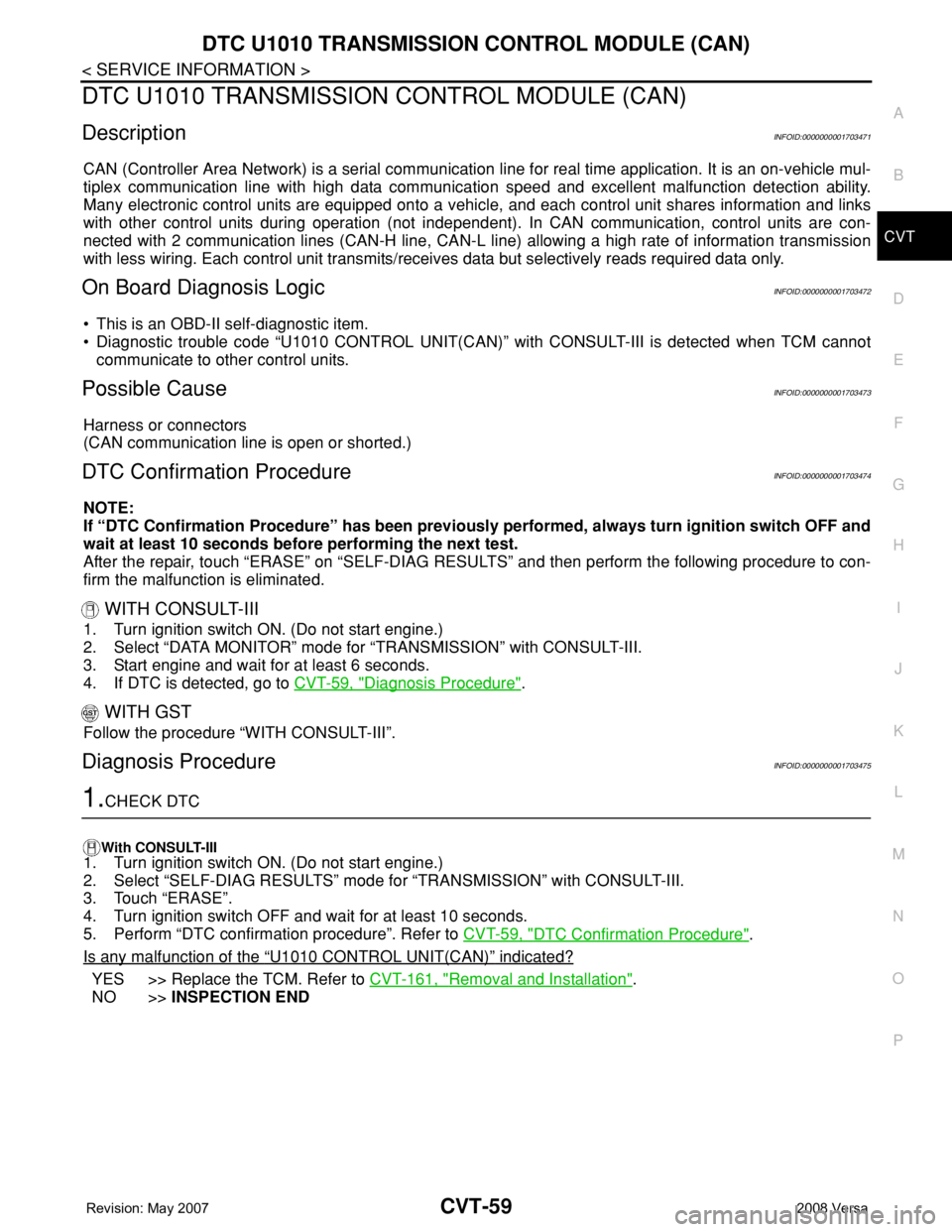
DescriptionINFOID:0000000001703471
CAN (Controller Area Network) is a serial communication line for real time application. It is an on-vehicle mul-
tiplex communication line with high data communication speed and excellent malfunction detection ability.
Many electronic control units are equipped onto a vehicle, and each control unit shares information and links
with other control units during operation (not independent). In CAN communication, control units are con-
nected with 2 communication lines (CAN-H line, CAN-L line) allowing a high rate of information transmission
with less wiring. Each control unit transmits/receives data but selectively reads required data only.
On Board Diagnosis LogicINFOID:0000000001703472
• This is an OBD-II self-diagnostic item.
• Diagnostic trouble code “U1010 CONTROL UNIT(CAN)” with CONSULT-III is detected when TCM cannot
communicate to other control units.
Possible CauseINFOID:0000000001703473
Harness or connectors
(CAN communication line is open or shorted.)
DTC Confirmation ProcedureINFOID:0000000001703474
NOTE:
If “DTC Confirmation Procedure” has been previously performed, always turn ignition switch OFF and
wait at least 10 seconds before performing the next test.
After the repair, touch “ERASE” on “SELF-DIAG RESULTS” and then perform the following procedure to con-
firm the malfunction is eliminated.
WITH CONSULT-III
1. Turn ignition switch ON. (Do not start engine.)
2. Select “DATA MONITOR” mode for “TRANSMISSION” with CONSULT-III.
3. Start engine and wait for at least 6 seconds.
4. If DTC is detected, go to CVT-59, "
Diagnosis Procedure".
WITH GST
Follow the procedure “WITH CONSULT-III”.
Diagnosis ProcedureINFOID:0000000001703475
1.CHECK DTC
With CONSULT-III
1. Turn ignition switch ON. (Do not start engine.)
2. Select “SELF-DIAG RESULTS” mode for “TRANSMISSION” with CONSULT-III.
3. Touch “ERASE”.
4. Turn ignition switch OFF and wait for at least 10 seconds.
5. Perform “DTC confirmation procedure”. Refer to CVT-59, "
DTC Confirmation Procedure".
Is any malfunction of the
“U1010 CONTROL UNIT(CAN)” indicated?
YES >> Replace the TCM. Refer to CVT-161, "Removal and Installation".
NO >>INSPECTION END