2008 NISSAN LATIO cruise control
[x] Cancel search: cruise controlPage 1 of 2771

-1
QUICK REFERENCE INDEX
AGENERAL INFORMATIONGIGeneral Information
BENGINEEMEngine Mechanical
LUEngine Lubrication System
COEngine Cooling System
ECEngine Control System
FLFuel System
EXExhaust System
ACCAccelerator Control System
CTRANSMISSION/
TRANSAXLECLClutch System
MTManual Transaxle
ATAutomatic Transaxle
CVTCVT
DDRIVELINE/AXLEFAXFront Axle
RAXRear Axle
ESUSPENSIONFSUFront Suspension
RSURear Suspension
WTRoad Wheels & Tires
FBRAKESBRBrake System
PBParking Brake System
BRCBrake Control System
GSTEERINGPSPower Steering System
STCSteering Control System
HRESTRAINTSSBSeat Belts
SRSSupplemental Restraint System (SRS)
IBODYBLBody, Lock & Security System
GWGlasses, Window System & Mirrors
RFRoof
EIExterior & Interior
IPInstrument Panel
SESeat
JAIR CONDITIONERMTCManual Air Conditioner
KELECTRICALSCStarting & Charging System
LTLighting System
DIDriver Information System
WWWiper, Washer & Horn
BCSBody Control System
LANLAN System
AVAudio Visual, Navigation & Telephone System
ACSAuto Cruise Control System
PGPower Supply, Ground & Circuit Elements
LMAINTENANCEMAMaintenance
Edition: May 2007
Revision: May 2007
Publication No. SM8E-1C11U0
B
D
© 2007 NISSAN NORTH AMERICA, INC.
All rights reserved. No part of this Service Manual may be reproduced or stored in a retrieval system, or transmitted in any
form, or by any means, electronic, mechanical, photo-copying, recording or otherwise, without the prior written permission
of Nissan North America Inc.
A
C
E
F
G
H
I
J
K
L
M
Page 11 of 2771

ACS-1
ELECTRICAL
C
D
E
F
G
H
I
J
L
M
SECTION ACS
A
B
ACS
N
O
P
CONTENTS
AUTO CRUISE CONTROL SYSTEM
SERVICE INFORMATION ............................2AUTOMATIC SPEED CONTROL DEVICE
(ASCD) ...............................................................
2
Description ................................................................2
Page 13 of 2771

AT-1
TRANSMISSION/TRANSAXLE
D
E
F
G
H
I
J
K
L
M
SECTION AT
A
B
AT
N
O
P
CONTENTS
AUTOMATIC TRANSAXLE
SERVICE INFORMATION ............................5
INDEX FOR DTC .................................................5
Alphabetical Index .....................................................5
DTC No. Index ..........................................................5
PRECAUTIONS ...................................................7
Precaution for Supplemental Restraint System
(SRS) "AIR BAG" and "SEAT BELT PRE-TEN-
SIONER" ...................................................................
7
Precaution Necessary for Steering Wheel Rota-
tion After Battery Disconnect .....................................
7
Precaution for On Board Diagnosis (OBD) System
of A/T and Engine .....................................................
7
Precaution .................................................................8
Service Notice or Precaution .....................................9
PREPARATION ..................................................10
Special Service Tool ...............................................10
Commercial Service Tool ........................................13
A/T FLUID ...........................................................15
Checking A/T Fluid ..................................................15
Changing A/T Fluid .................................................15
A/T Fluid Cooler Cleaning .......................................16
A/T CONTROL SYSTEM ....................................19
Cross-Sectional View ..............................................19
Shift Mechanism ......................................................19
TCM Function ..........................................................27
CAN Communication ...............................................28
Input/Output Signal of TCM .....................................28
Line Pressure Control .............................................29
Shift Control ............................................................30
Lock-up Control .......................................................31
Engine Brake Control (Overrun Clutch Control) ......32
Control Valve ...........................................................34
Centrifugal Cancel Mechanism ...............................34
ON BOARD DIAGNOSTIC (OBD) SYSTEM ......36
Introduction .............................................................36
OBD-II Function for A/T System ..............................36
One or Two Trip Detection Logic of OBD-II .............36
OBD-II Diagnostic Trouble Code (DTC) ..................36
Malfunction Indicator Lamp (MIL) ............................38
TROUBLE DIAGNOSIS ....................................39
DTC Inspection Priority Chart ..................................39
Fail-Safe ..................................................................39
How to Perform Trouble Diagnosis for Quick and
Accurate Repair .......................................................
40
A/T Electrical Parts Location ...................................46
Circuit Diagram ........................................................47
Inspections Before Trouble Diagnosis .....................48
Road Test ................................................................52
Check Before Engine Is Started ..............................53
Check at Idle ............................................................53
Cruise Test - Part 1 .................................................55
Cruise Test - Part 2 .................................................58
Cruise Test - Part 3 .................................................59
Vehicle Speed at Which Gear Shifting Occurs ........61
Vehicle Speed at Which Lock-up Occurs/Releas-
es .............................................................................
61
Symptom Chart ........................................................61
TCM Terminal and Reference Value .......................71
CONSULT-III Function (A/T) ...................................73
Diagnosis Procedure without CONSULT-III ............78
DTC U1000 CAN COMMUNICATION LINE .....83
Description ...............................................................83
On Board Diagnosis Logic .......................................83
Possible Cause ........................................................83
DTC Confirmation Procedure ..................................83
Wiring Diagram - AT - CAN .....................................84
Diagnosis Procedure ...............................................85
DTC P0705 PARK/NEUTRAL POSITION
(PNP) SWITCH ..................................................
86
Description ...............................................................86
CONSULT-III Reference Value in Data Monitor
Mode ........................................................................
86
On Board Diagnosis Logic .......................................86
Possible Cause ........................................................86
Page 64 of 2771

AT-52
< SERVICE INFORMATION >
TROUBLE DIAGNOSIS
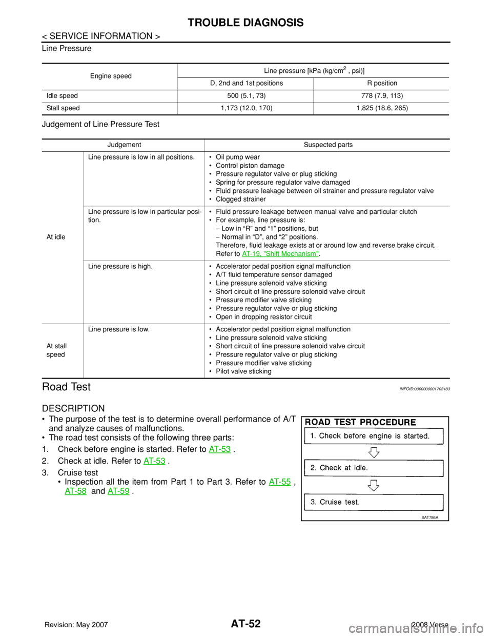
Line Pressure
Judgement of Line Pressure Test
Road TestINFOID:0000000001703183
DESCRIPTION
• The purpose of the test is to determine overall performance of A/T
and analyze causes of malfunctions.
• The road test consists of the following three parts:
1. Check before engine is started. Refer to AT- 5 3
.
2. Check at idle. Refer to AT- 5 3
.
3. Cruise test
• Inspection all the item from Part 1 to Part 3. Refer to AT- 5 5
,
AT- 5 8
and AT- 5 9 .
Engine speedLine pressure [kPa (kg/cm
2 , psi)]
D, 2nd and 1st positions R position
Idle speed 500 (5.1, 73) 778 (7.9, 113)
Stall speed 1,173 (12.0, 170) 1,825 (18.6, 265)
Judgement Suspected parts
At idleLine pressure is low in all positions. • Oil pump wear
• Control piston damage
• Pressure regulator valve or plug sticking
• Spring for pressure regulator valve damaged
• Fluid pressure leakage between oil strainer and pressure regulator valve
• Clogged strainer
Line pressure is low in particular posi-
tion.• Fluid pressure leakage between manual valve and particular clutch
• For example, line pressure is:
− Low in “R” and “1” positions, but
− Normal in “D”, and “2” positions.
Therefore, fluid leakage exists at or around low and reverse brake circuit.
Refer to AT- 1 9 , "
Shift Mechanism".
Line pressure is high. • Accelerator pedal position signal malfunction
• A/T fluid temperature sensor damaged
• Line pressure solenoid valve sticking
• Short circuit of line pressure solenoid valve circuit
• Pressure modifier valve sticking
• Pressure regulator valve or plug sticking
• Open in dropping resistor circuit
At stall
speedLine pressure is low. • Accelerator pedal position signal malfunction
• Line pressure solenoid valve sticking
• Short circuit of line pressure solenoid valve circuit
• Pressure regulator valve or plug sticking
• Pressure modifier valve sticking
• Pilot valve sticking
SAT786A
Page 70 of 2771

AT-58
< SERVICE INFORMATION >
TROUBLE DIAGNOSIS
• Continue “Road Test”.
8.CHECK SHIFT-DOWN (D4 TO D3 )
Decelerate vehicle by applying foot brake lightly.
Read gear position and engine speed. Refer to AT-73, "
CON-
SULT-III Function (A/T)" .
Does engine speed return to idle smoothly when A/T is shifted from
D4 to D3 ?
YES >> 1. Stop vehicle.
2. Go to AT-58, "
Cruise Test - Part 2" .
NO >> • Mark the box on the AT-40, "
How to Perform Trouble
Diagnosis for Quick and Accurate Repair" .
•Go to AT-192, "
Engine Speed Does Not Return to Idle
(Light Braking D4→ D3)" .
• Continue “Road Test”.
Cruise Test - Part 2INFOID:0000000001703187
1.CHECK STARTING GEAR (D1 ) POSITION
1. Push overdrive control switch. (OD OFF indicator lamp is off.)
2. Move selector lever to “D” position.
3. Accelerate vehicle by half throttle again.
Read gear position. Refer to AT-73, "
CONSULT-III Func-
tion (A/T)" .
Does vehicle start from D
1 ?
YES >> GO TO 2.
NO >> • Mark the box on the AT-40, "
How to Perform Trouble
Diagnosis for Quick and Accurate Repair" .
•Go to AT-183, "
Vehicle Cannot Be Started from D1" .
• Continue “Road Test”.
2.CHECK SHIFT-UP AND SHIFT-DOWN (D3 TO D4 TO D2 )
1. Accelerate vehicle to 80 km/h (50 MPH) as shown in the figure.
2. Release accelerator pedal and then quickly depress it fully.
Read gear position and throttle opening. Refer to AT-73,
"CONSULT-III Function (A/T)" .
Does A/T shift from D
4 to D2 as soon as accelerator pedal is
depressed fully?
YES >> GO TO 3.
NO >> • Mark the box on the AT-40, "
How to Perform Trouble
Diagnosis for Quick and Accurate Repair" .
•Go to AT-185, "
A/T Does Not Shift: D1→ D2or Does
Not Kickdown: D4→ D2" .
• Continue “Road Test”.
3.CHECK SHIFT-UP (D2 TO D3 )
Check shift-up (D
2 to D3 )
Specified speed when shifting from D
2 to D3 . Refer to AT-61, "Vehicle Speed at Which Gear Shifting Occurs" .
SAT959I
SAT495G
SCIA7192E
Page 71 of 2771

TROUBLE DIAGNOSIS
AT-59
< SERVICE INFORMATION >
D
E
F
G
H
I
J
K
L
MA
B
AT
N
O
P
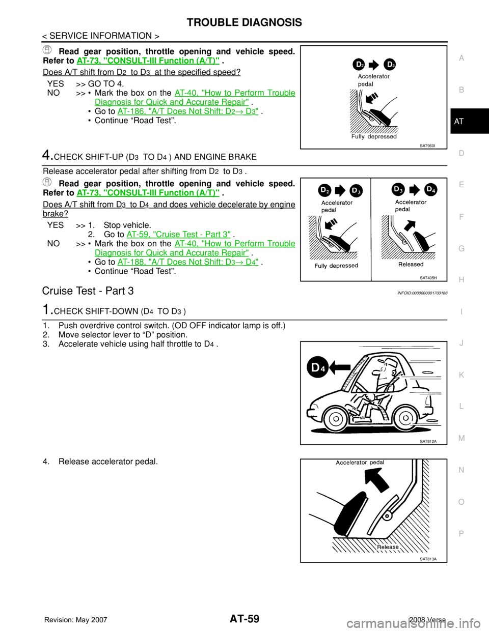
Read gear position, throttle opening and vehicle speed.
Refer to AT-73, "
CONSULT-III Function (A/T)" .
Does A/T shift from D
2 to D3 at the specified speed?
YES >> GO TO 4.
NO >> • Mark the box on the AT-40, "
How to Perform Trouble
Diagnosis for Quick and Accurate Repair" .
•Go to AT-186, "
A/T Does Not Shift: D2→ D3" .
• Continue “Road Test”.
4.CHECK SHIFT-UP (D3 TO D4 ) AND ENGINE BRAKE
Release accelerator pedal after shifting from D
2 to D3 .
Read gear position, throttle opening and vehicle speed.
Refer to AT-73, "
CONSULT-III Function (A/T)" .
Does A/T shift from D
3 to D4 and does vehicle decelerate by engine
brake?
YES >> 1. Stop vehicle.
2. Go to AT-59, "
Cruise Test - Part 3" .
NO >> • Mark the box on the AT-40, "
How to Perform Trouble
Diagnosis for Quick and Accurate Repair" .
•Go to AT-188, "
A/T Does Not Shift: D3→ D4" .
• Continue “Road Test”.
Cruise Test - Part 3INFOID:0000000001703188
1.CHECK SHIFT-DOWN (D4 TO D3 )
1. Push overdrive control switch. (OD OFF indicator lamp is off.)
2. Move selector lever to “D” position.
3. Accelerate vehicle using half throttle to D
4 .
4. Release accelerator pedal.
SAT960I
SAT405H
SAT812A
SAT813A
Page 88 of 2771

AT-76
< SERVICE INFORMATION >
TROUBLE DIAGNOSIS
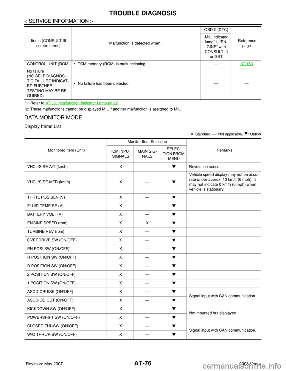
*1: Refer to AT- 3 8 , "Malfunction Indicator Lamp (MIL)" .
*2: These malfunctions cannot be displayed MIL if another malfunction is assigned to MIL.
DATA MONITOR MODE
Display Items List
X: Standard, —: Not applicable, : Option
CONTROL UNIT (ROM) • TCM memory (ROM) is malfunctioning. —AT- 1 6 3
No failure
(NO SELF DIAGNOS-
TIC FAILURE INDICAT-
ED FURTHER
TESTING MAY BE RE-
QUIRED)• No failure has been detected. — — Items (CONSULT-III
screen terms)Malfunction is detected when...OBD-II (DTC)
Reference
page MIL indicator
lamp*1, “EN-
GINE” with
CONSULT-III
or GST
Monitored item (Unit)Monitor Item Selection
Remarks
TCM INPUT
SIGNALSMAIN SIG-
NALSSELEC-
TION FROM
MENU
VHCL/S SE-A/T (km/h)X — Revolution sensor
VHCL/S SE-MTR (km/h) X —Vehicle speed display may not be accu-
rate under approx. 10 km/h (6 mph). It
may not indicate 0 km/h (0 mph) when
vehicle is stationary.
THRTL POS SEN (V) X —
FLUID TEMP SE (V) X —
BATTERY VOLT (V) X —
ENGINE SPEED (rpm) X X
TURBINE REV (rpm) X —
OVERDRIVE SW (ON/OFF) X —
PN POSI SW (ON/OFF) X —
R POSITION SW (ON/OFF) X —
D POSITION SW (ON/OFF) X —
2 POSITION SW (ON/OFF) X —
1 POSITION SW (ON/OFF) X —
ASCD-CRUISE (ON/OFF) X —
Signal input with CAN communication.
ASCD-OD CUT (ON/OFF) X —
KICKDOWN SW (ON/OFF) X —
Not mounted but displayed.
POWERSHIFT SW (ON/OFF) X —
CLOSED THL/SW (ON/OFF) X —
Signal input with CAN communication.
W/O THRL/P-SW (ON/OFF) X —
Page 129 of 2771

DTC P0734 A/T 4TH GEAR FUNCTION
AT-117
< SERVICE INFORMATION >
D
E
F
G
H
I
J
K
L
MA
B
AT
N
O
P
- Valve, sleeve and plug slide along valve bore under their own weight.
- Valve, sleeve and plug are free from burrs, dents and scratches.
- Control valve springs are free from damage, deformation and fatigue.
- Hydraulic line is free from obstacles.
OK or NG
OK >> GO TO 6.
NG >> Repair control valve.
6.CHECK SHIFT-UP (D3 TO D4)
During AT-55, "
Cruise Test - Part 1".
Does A/T shift from D
3 to D4 at the specified speed?
YES >> GO TO 11.
NO >> Check control valve again. Repair or replace control
valve assembly.
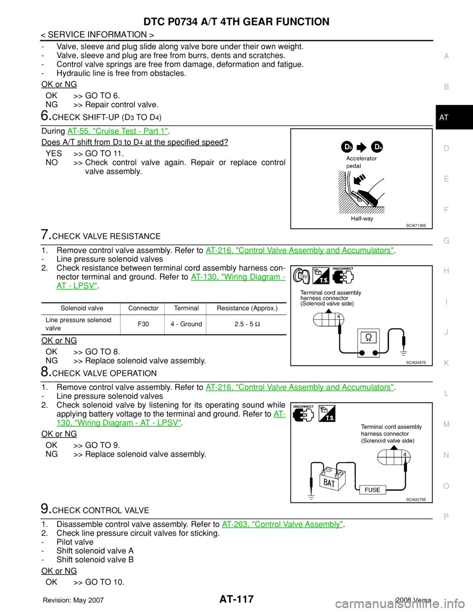
7.CHECK VALVE RESISTANCE
1. Remove control valve assembly. Refer to AT-216, "
Control Valve Assembly and Accumulators".
- Line pressure solenoid valves
2. Check resistance between terminal cord assembly harness con-
nector terminal and ground. Refer to AT-130, "
Wiring Diagram -
AT - L P S V".
OK or NG
OK >> GO TO 8.
NG >> Replace solenoid valve assembly.
8.CHECK VALVE OPERATION
1. Remove control valve assembly. Refer to AT-216, "
Control Valve Assembly and Accumulators".
- Line pressure solenoid valves
2. Check solenoid valve by listening for its operating sound while
applying battery voltage to the terminal and ground. Refer to AT-
130, "Wiring Diagram - AT - LPSV".
OK or NG
OK >> GO TO 9.
NG >> Replace solenoid valve assembly.
9.CHECK CONTROL VALVE
1. Disassemble control valve assembly. Refer to AT-263, "
Control Valve Assembly".
2. Check line pressure circuit valves for sticking.
- Pilot valve
- Shift solenoid valve A
- Shift solenoid valve B
OK or NG
OK >> GO TO 10.
SCIA7190E
Solenoid valve Connector Terminal Resistance (Approx.)
Line pressure solenoid
valveF30 4 - Ground 2.5 - 5 Ω
SCIA3457E
SCIA3275E