2008 MERCEDES-BENZ CLS COUPE tow
[x] Cancel search: towPage 252 of 329
Troubleshooting
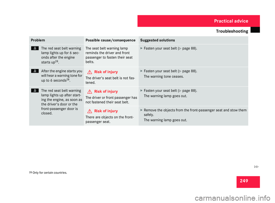
249Problem Possible cause/consequence Suggested solutions
<
The red seat belt warning
lamp lights up for 6 sec-
onds after the engine
starts up 28
. The seat belt warning lamp
reminds the driver and front
passenger to fasten their seat
belts. X
Fasten your seat belt ( Y page 88).<
After the engine starts you
will
hear a warning tone for
up to 6 seconds 28
. G
Risk of injury
The driver's seat belt is not fas-
tened. X
Fasten your seat belt ( Y page 88).
The warning tone ceases. <
The red seat belt warning
lamp lights up after start-
ing the engine, as soon as
the driver's door or the
front-passenger door is
closed. G
Risk of injury
The driver or front passenger has
not fastened their seat belt. X
Fasten your seat belt ( Y page 88).
The warning lamp goes out. G
Risk of injury
There are objects on the front-
passenger seat. X
Remove the objects from the front-passenger seat and stow them
safely.
The warning lamp goes out. 28
Only for certain countries. Practical advice
219_AKB; 2; 4, en-GB
mkalafa,
2007-11-13T09:28:36+01:00 - Seite 249 Z
Page 253 of 329
Troubleshooting
250 Problem Possible cause/consequence Suggested solutions
<
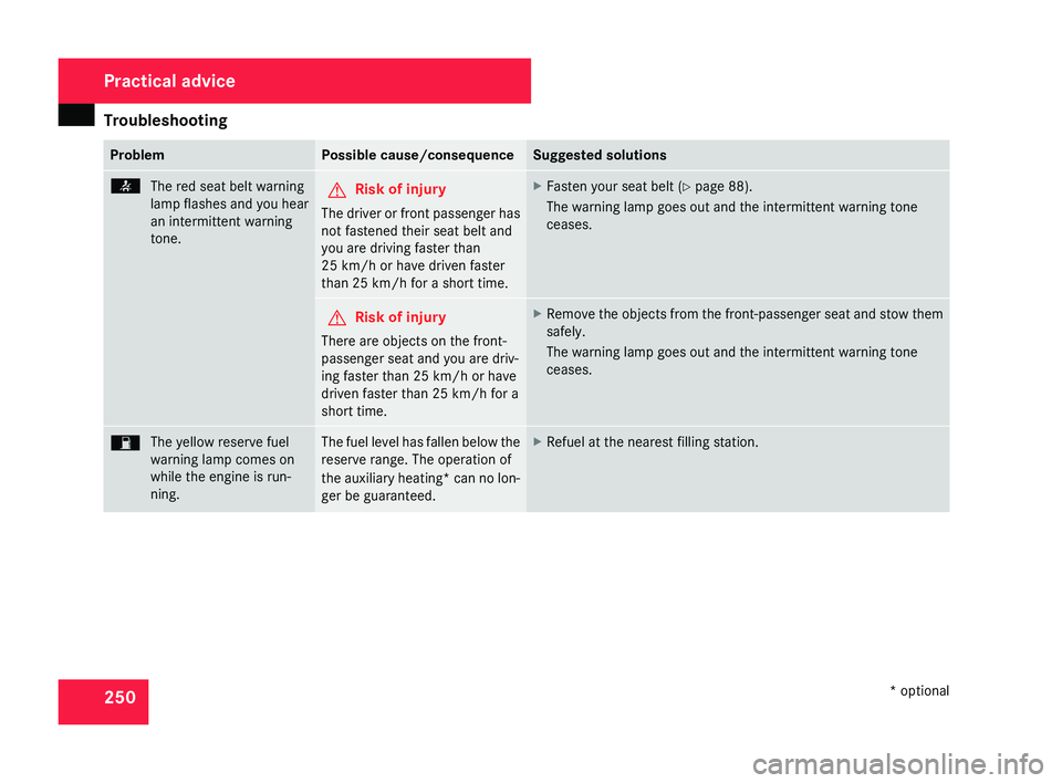
The red seat belt warning
lamp
flashes and you hear
an intermittent warning
tone. G
Risk of injury
The driver or front passenger has
not fastened their seat belt and
you are driving faster than
25 km/h
or have driven faster
than 25 km/h for a short time. X
Fasten your seat belt ( Y page 88).
The warning lamp goes out and the intermittent warning tone
ceases. G
Risk of injury
There are objects on the front-
passenger seat and you are driv-
ing faster than 25 km/h
or have
driven faster than 25 km/h for a
short time. X
Remove the objects from the front-passenger seat and stow them
safely.
The warning lamp goes out and the intermittent warning tone
ceases. W
The yellow reserve fuel
warning lamp comes on
while the engine is run-
ning. The fuel level has fallen below the
reserve range. The operation of
the
auxiliary heating* can no lon-
ger be guaranteed. X
Refuel at the nearest filling station. Practical advice
* optional
219_AKB; 2; 4, en-GB
mkalafa,
2007-11-13T09:28:36+01:00 - Seite 250
Page 271 of 329
Locking/unlocking in an emergency
268
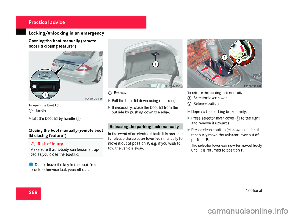
Opening the boot manually (remote
boot lid closing feature*)
To open the boot lid
1
Handle
X Lift the boot lid by handle 1.
Closing the boot manually (remote boot
lid closing feature*) G
Risk of injury
Make sure that nobody can become trap-
ped as you close the boot lid.
i Do not leave the key in the boot. You
could otherwise lock yourself out. 1
Recess
X Pull the boot lid down using recess 1.
X If necessary, close the boot lid from the
outside by pushing down the edge. Releasing the parking lock manually
In the event of an electrical fault, it is possible
to release the selector lever lock manually to
move it out of position P, e.g. if you wish to
tow the vehicle away. To release the parking lock manually
1
Selector lever cover
2 Release button
X Depress the parking brake firmly.
X Press selector lever cover 1 to the right
and remove it upwards.
X Press release button 2 down and simul-
taneously move the selector lever out of
position P.
The selector lever can now be moved freely
until it is returned to position P. Practical advice
* optional
219_AKB; 2; 4, en-GB
mkalafa,
2007-11-13T09:28:36+01:00 - Seite 268
Page 280 of 329
Flat tyre
277Do not start the engine at any time while
the wheel is being changed.
Do not lie under the vehicle when it is being
supported by the jack. If you do not raise
the vehicle as described, it could slip off the
jack (e.g. if the engine is started or a door
or the boot lid are opened or closed) and
you could be seriously injured.
Using the TIREFIT kit
You can use the TIREFIT kit to seal small
punctures, particularly those in the tyre tread.
You can use TIREFIT in outdoor temperatures
down to -20 °C. G
Risk of accident
In the following situations, your safety is at
particular risk and TIREFIT is unable to pro-
vide breakdown assistance:
R if there are cuts or punctures in the tyre
greater than 4 mm
R if the wheel rim is damaged
R if you have driven at very low tyre pres-
sures or on a flat tyre
Do not drive any further. Consult a qualified
specialist workshop which has the neces- sary specialist knowledge and tools to carry
out the work required.
Mercedes-Benz recommends that you use
a Mercedes-Benz Service Centre for this
purpose. In particular, work relevant to
safety or on safety-related systems must be
carried out at a qualified specialist work-
shop.
X Do not remove any foreign objects which
have penetrated the tyre, e.g. screws or
nails.
X Remove TIREFIT, the accompanying "max.
80 km/h" sticker and the electric air pump
from the stowage well underneath the boot
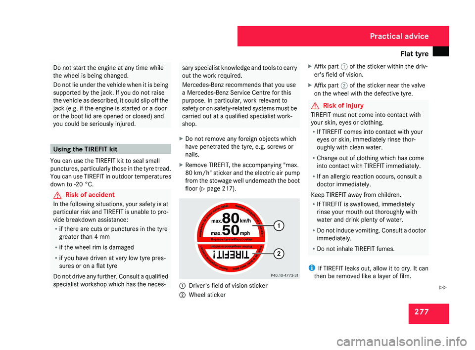
floor ( Y page 217).1
Driver's field of vision sticker
2 Wheel sticker X
Affix part 1 of the sticker within the driv-
er's field of vision.
X Affix part 2 of the sticker near the valve
on the wheel with the defective tyre.
G Risk of injury
TIREFIT must not come into contact with
your skin, eyes or clothing.
R If TIREFIT comes into contact with your
eyes or skin, immediately rinse thor-
oughly with clean water.
R Change out of clothing which has come
into contact with TIREFIT immediately.
R If an allergic reaction occurs, consult a
doctor immediately.
Keep TIREFIT away from children.
R If TIREFIT is swallowed, immediately
rinse your mouth out thoroughly with
water and drink plenty of water.
R Do not induce vomiting. Consult a doctor
immediately.
R Do not inhale TIREFIT fumes.
i If TIREFIT leaks out, allow it to dry. It can
then be removed like a layer of film.
Practical advice
219_AKB; 2; 4, en-GB
mkalafa,
2007-11-13T09:28:36+01:00 - Seite 277
Z
Page 282 of 329
Flat tyre
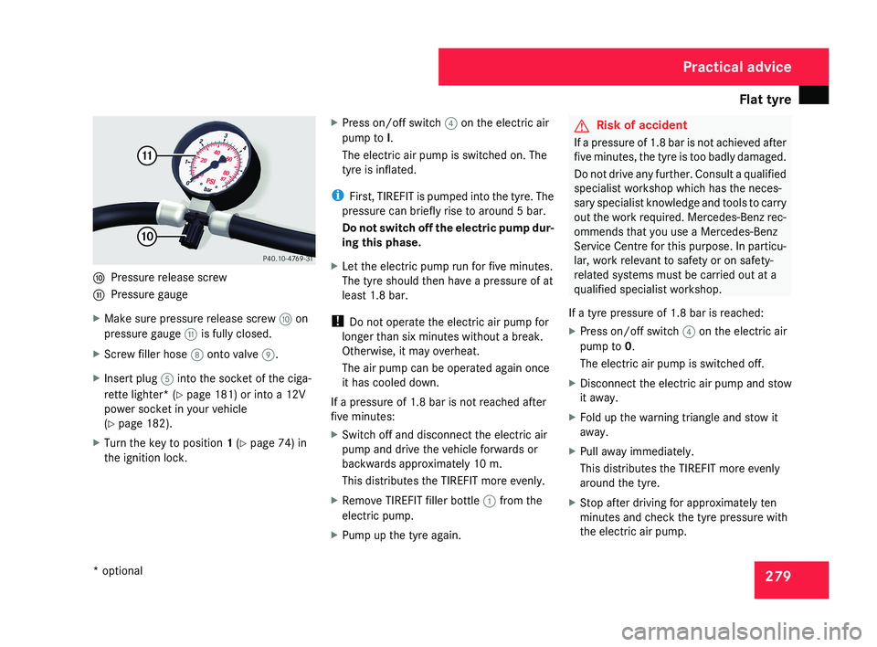
279a
Pressure release screw
b Pressure gauge
X Make sure pressure release screw a on
pressure gauge b is fully closed.
X Screw filler hose 8 onto valve 9.
X Insert plug 5 into the socket of the ciga-
rette lighter* (Y page 181) or into a 12V
power socket in your vehicle
(Y page 182).
X Turn the key to position 1 (Y page 74) in
the ignition lock. X
Press on/off switch 4 on the electric air
pump to I.
The electric air pump is switched on. The
tyre is inflated.
i First, TIREFIT is pumped into the tyre. The
pressure can briefly rise to around 5 bar.
Do not switch off the electric pump dur-
ing this phase.
X Let the electric pump run for five minutes.
The tyre should then have a pressure of at
least 1.8 bar.
! Do not operate the electric air pump for
longer than six minutes without a break.
Otherwise, it may overheat.
The air pump can be operated again once
it has cooled down.
If a pressure of 1.8 bar is not reached after
five minutes:
X Switch off and disconnect the electric air
pump and drive the vehicle forwards or
backwards approximately 10 m.
This distributes the TIREFIT more evenly.
X Remove TIREFIT filler bottle 1 from the
electric pump.
X Pump up the tyre again.
G Risk of accident
If a pressure of 1.8 bar is not achieved after
five minutes, the tyre is too badly damaged.
Do not drive any further. Consult a qualified
specialist workshop which has the neces-
sary specialist knowledge and tools to carry
out the work required. Mercedes-Benz rec-
ommends that you use a Mercedes-Benz
Service Centre for this purpose. In particu-
lar, work relevant to safety or on safety-
related systems must be carried out at a
qualified specialist workshop.
If a tyre pressure of 1.8 bar is reached:
X Press on/off switch 4 on the electric air
pump to 0.
The electric air pump is switched off.
X Disconnect the electric air pump and stow
it away.
X Fold up the warning triangle and stow it
away.
X Pull away immediately.
This distributes the TIREFIT more evenly
around the tyre.
X Stop after driving for approximately ten
minutes and check the tyre pressure with
the electric air pump.
Practical advice
* optional
219_AKB; 2; 4, en-GB
mkalafa,
2007-11-13T09:28:36+01:00 - Seite 279
Page 284 of 329

Flat tyre
2817
Valve
8 Filler hose
X Remove the cap from valve 7 on the faulty
tyre.
X Screw filler hose 8 onto valve 7.
X Insert plug 4 into the socket of the ciga-
rette lighter* (Y page 181) or into a 12V
power socket in your vehicle
(Y page 182).
X Turn the key to position 1 in the ignition
lock. X
Press on/off switch 3 on the electric air
pump to I.
The electric air pump is switched on. The
tyre is inflated.
i First, TIREFIT is pumped into the tyre. The
pressure can briefly rise to around 5 bar.
Do not switch off the electric pump dur-
ing this phase.
X Let the electric pump run for five minutes.
The tyre should then have a pressure of at
least 1.8 bar.
! Do not operate the electric air pump for
longer than six minutes without a break.
Otherwise, it may overheat.
The air pump can be operated again once
it has cooled down.
If a pressure of 1.8 bar is not reached after
five minutes:
X Switch off and disconnect the electric air
pump and drive the vehicle forwards or
backwards approximately 10 m.
This distributes the TIREFIT more evenly.
X Remove TIREFIT filler bottle 1 from the
electric pump.
X Pump up the tyre again.
G Risk of accident
If a pressure of 1.8 bar is not achieved after
five minutes, the tyre is too badly damaged.
Do not drive any further. Consult a qualified
specialist workshop which has the neces-
sary specialist knowledge and tools to carry
out the work required. Mercedes-Benz rec-
ommends that you use a Mercedes-Benz
Service Centre for this purpose. In particu-
lar, work relevant to safety or on safety-
related systems must be carried out at a
qualified specialist workshop.
If a tyre pressure of 1.8 bar is reached:
X Press on/off switch 3 on the electric air
pump to 0.
The electric air pump is switched off.
X Disconnect the electric air pump and stow
it away.
X Fold up the warning triangle and stow it
away.
X Pull away immediately.
This distributes the TIREFIT more evenly
around the tyre.
X Stop after driving for approximately ten
minutes and check the tyre pressure with
the electric air pump.
Practical advice
* optional
219_AKB; 2; 4, en-GB
mkalafa,
2007-11-13T09:28:36+01:00 - Seite 281
Page 286 of 329
Flat tyre
283required. Mercedes-Benz recommends
that you use a Mercedes-Benz Service
Centre for this purpose. In particular, work
relevant to safety or on safety-related sys-
tems must be carried out at a qualified
specialist workshop.
Preparing the vehicle X
Prepare the vehicle as described
(Y page 276).
X Place the wheels in the straight-ahead posi-
tion.
X Take the following from the stowage well
beneath the boot floor:
R
the "Minispare"/collapsible emergency
spare wheel* or the spare wheel*
R the vehicle tool kit
R the wheel chock
R the jack
X Secure the vehicle to prevent it from rolling
away.
On level ground: place chocks or similar
under the front and rear of the wheel that
is diagonally opposite the wheel you wish
to change. X
On downhill gradients: place chocks or
similar under both wheels of the other axle.
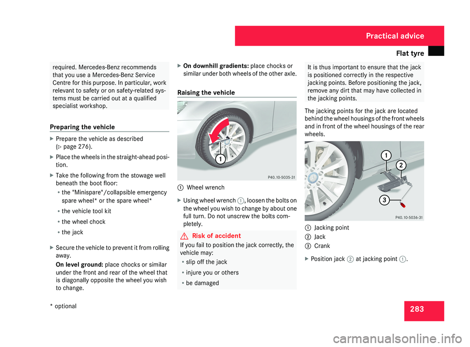
Raising the vehicle 1
Wheel wrench
X Using wheel wrench 1, loosen the bolts on
the wheel you wish to change by about one
full turn. Do not unscrew the bolts com-
pletely. G
Risk of accident
If you fail to position the jack correctly, the
vehicle may:
R slip off the jack
R injure you or others
R be damaged It is thus important to ensure that the jack
is positioned correctly in the respective
jacking points. Before positioning the jack,
remove any dirt that may have collected in
the jacking points.
The jacking points for the jack are located
behind the wheel housings of the front wheels
and in front of the wheel housings of the rear
wheels. 1
Jacking point
2 Jack
3 Crank
X Position jack 2 at jacking point 1. Practical advice
* optional
219_AKB; 2; 4, en-GB
mkalafa,
2007-11-13T09:28:36+01:00 - Seite 283
Page 288 of 329
Flat tyre
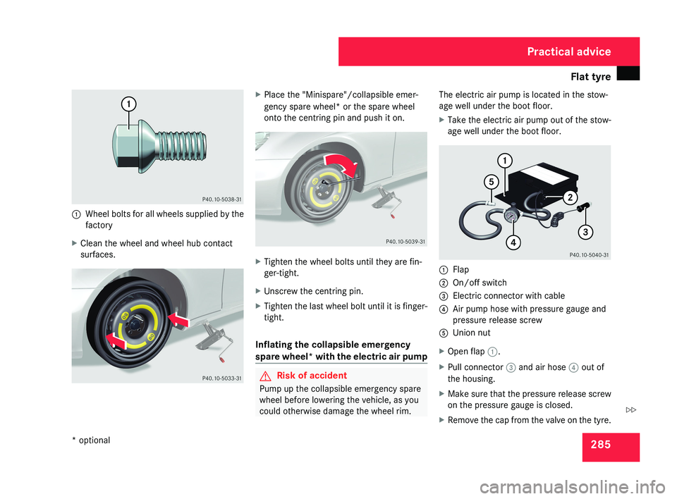
2851
Wheel bolts for all wheels supplied by the
factory
X Clean the wheel and wheel hub contact
surfaces.
XPlace the "Minispare"/collapsible emer-
gency spare wheel* or the spare wheel
onto the centring pin and push it on.
XTighten the wheel bolts until they are fin-
ger-tight.
X Unscrew the centring pin.
X Tighten the last wheel bolt until it is finger-
tight.
Inflating the collapsible emergency
spare wheel* with the electric air pump
G Risk of accident
Pump up the collapsible emergency spare
wheel before lowering the vehicle, as you
could otherwise damage the wheel rim. The electric air pump is located in the stow-
age well under the boot floor.
X
Take the electric air pump out of the stow-
age well under the boot floor.
1 Flap
2 On/off switch
3 Electric connector with cable
4 Air pump hose with pressure gauge and
pressure release screw
5 Union nut
X Open flap 1.
X Pull connector 3 and air hose 4 out of
the housing.
X Make sure that the pressure release screw
on the pressure gauge is closed.
X Remove the cap from the valve on the tyre.
Practical advice
* optional
219_AKB; 2; 4, en-GB
mkalafa,
2007-11-13T09:28:36+01:00 - Seite 285
Z