2008 MERCEDES-BENZ CLS COUPE tow
[x] Cancel search: towPage 148 of 329
Driving systems
145
Activating HOLD X
Make sure that the activation conditions
are met.
X Depress the brake.
X Depress the brake again quickly until
HOLD appears in the display.
HOLD is activated. You can release the
brake pedal.
i If depressing the brake pedal the first
time does not activate HOLD, wait briefly
and then try again. G
Risk of accident
The vehicle's brakes are applied when
HOLD is activated. For this reason, deacti-
vate HOLD if the vehicle is to be set in
motion by other means (e.g. in a car wash
or by towing).
Deactivating HOLD HOLD is deactivated if:
R
you
accelerate when the selector lever is in
position D or R
R you move the selector lever to position P
R you release the brakes completely and
apply them again with a certain amount of pressure until the
HOLD message in the
multi-function display goes out G
Risk of accident
Never get out of the vehicle when HOLD is
activated.
HOLD
must never be operated or deactiva-
ted by a passenger or from outside the
vehicle.
HOLD does not replace the parking brake
and must not be used for parking.
The HOLD braking effect is cancelled and
the vehicle can start moving if:
R HOLD is deactivated by depressing the
accelerator pedal or the brake pedal
R there is a malfunction in the system or an
interruption in the power supply, e.g. bat-
tery failure
R the electrical system in the engine com-
partment, the battery or the fuses are
tampered with
R the battery is disconnected G
Risk of accident
If you wish to leave the vehicle or park it,
deactivate HOLD and secure the vehicle
against rolling away. You will see a warning message in the multi-
function display if HOLD is activated and:
R
the
driver's door is opened and you release
the seat belt
R the ignition is switched off
R the bonnet is opened
Selector lever in park position
X Move the selector lever to P
to prevent the
vehicle from rolling away.
HOLD is deactivated. The warning message
in the multi-function display goes out.
A horn will also sound at regular intervals if
HOLD is activated and you:
R stop
the engine and open the driver's door
R open the bonnet
The horn draws your attention to the fact that
the vehicle has been parked while HOLD is
still activated. The sound becomes louder if
you attempt to lock the vehicle. The vehicle
is not locked until HOLD is deactivated.
i If the ignition has been switched off, the
engine cannot be restarted until HOLD is
deactivated.
If there is a fault in the system or power supply
while HOLD is activated, the Brake immedi-
ately message appears in the multi-function Controls
219_AKB; 2; 4, en-GB
mkalafa,
2007-11-13T09:28:36+01:00 - Seite 145 Z
Page 152 of 329
Driving systems
149
Front sensors Centre Approximately 100 cm
Corners Approximately 60 cm
Rear sensors
Centre Approximately 120 cm
Corners Approximately 80 cm
!
Pay particular attention to objects above
or below the sensors when parking, such
as flower pots or trailer towbars. Parktronic
does not detect such objects when they are
in the immediate vicinity of the vehicle. You
could damage the vehicle or the objects.
Ultrasonic sources such as an automatic
car wash, a lorry's compressed-air brakes
or a pneumatic drill could cause Parktronic
to malfunction.
Minimum distance Centre Approximately 20 cm
Corners Approximately 15 cm If there is an obstacle within this range, all
warning displays light up and a tone sounds.
If the distance falls below the minimum clear-
ance, it may no longer be shown.
Warning displays
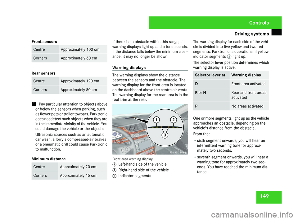
The warning displays show the distance
between the sensors and the obstacle. The
warning display for the front area is located
on the dashboard above the centre air vents.
The warning display for the rear area is in the
roof trim at the rear.
Front area warning display
1
Left-hand side of the vehicle
2 Right-hand side of the vehicle
3 Indicator segments The warning display for each side of the vehi-
cle is divided into five yellow and two red
segments. Parktronic is operational if yellow
indicator segments
3 light up.
The selector lever position determines which
warning display is active: Selector lever at Warning display
D Front area activated
R or N Rear and front areas
activated
P No areas activated
One or more segments light up as the vehicle
approaches an obstacle, depending on the
vehicle's distance from the obstacle.
From the:
R
sixth segment onwards, you will hear an
intermittent warning tone for approxi-
mately two seconds.
R seventh segment onwards, you will hear a
warning tone for approximately two sec-
onds. You have reached the minimum dis-
tance. Controls
219_AKB; 2; 4, en-GB
mkalafa,
2007-11-13T09:28:36+01:00 - Seite 149
Page 164 of 329
Air conditioning
161
Setting the centre air vents
Centre air vents
1
Centre air vent, left
2 Centre air vent, right
3 Thumbwheel for centre air vent, right
4 Thumbwheel for centre air vent, left
X To open/close: turn thumbwheels 3 and
4 up or down. Setting the side air vents Side air vents
1
Side window demister vent
2 Side air vent
3 Side air vent thumbwheel
X To open/close: turn thumbwheel 3 to the
left or right.
Setting the stowage compartment air
vent The stowage compartment can be ventilated,
for instance to cool its contents, when 2-zone
Thermatic/4-zone Thermotronic* is activa-
ted. The level of airflow to the stowage com-
partment depends on the airflow and air
distribution settings. The temperature of theair is approximately the same as that of the
air flowing from the centre air vents.
!
Close the stowage compartment air vent
when heating mode is activated and acti-
vate "cooling with air dehumidification" if
the outside temperature is high. Otherwise,
temperature-sensitive items stored in the
stowage compartment could be damaged. Stowage compartment air vent
1
Slide
X To open the vent: pull slide 1 up.
X To close the air vent: press slide 1 down. Controls
* optional
219_AKB; 2; 4, en-GB
mkalafa,
2007-11-13T09:28:36+01:00 - Seite 161
Page 175 of 329
Loading and stowing
172 Loading and stowing
Cup holder
G
Risk of injury
Keep the cup holder closed while the vehi-
cle is in motion. Otherwise, vehicle occu-
pants could be injured by objects being
thrown around if you:
R brake sharply
R change direction suddenly
R are involved in an accident
Only use the cup holders for containers of
a suitable size and which have lids. Other-
wise, the drinks could spill.
Cup holders should not be used for hot
drinks. Otherwise, you may scald yourself. Cup holder* in the centre console X
To open: press the marking on the cup
holder lightly.
The cup holder slides out automatically.
i You can remove the cup holder to clean
it. Clean the cup holder with clean, luke-
warm water only. When reinserting the cup
holder, make sure that you insert it into the
guides. X
To close: press the side of the cup holder
in the direction of the arrow.
Cup holder in the rear seat armrest X
To open: press the front of the cup holder.
The cup holder slides out automatically. Controls
* optional
219_AKB; 2; 4, en-GB
mkalafa,
2007-11-13T09:28:36+01:00 - Seite 172
Page 176 of 329
Loading and stowing
173
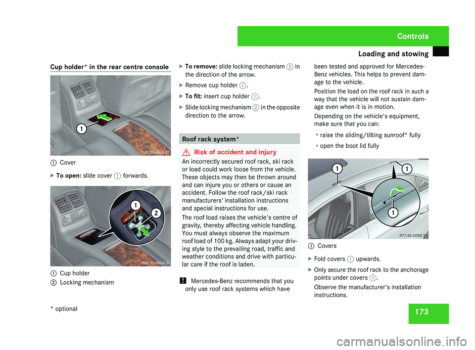
Cup holder* in the rear centre console
1
Cover
X To open: slide cover 1 forwards.1
Cup holder
2 Locking mechanism X
To remove: slide locking mechanism 2 in
the direction of the arrow.
X Remove cup holder 1.
X To fit: insert cup holder 1.
X Slide locking mechanism 2 in the opposite
direction to the arrow. Roof rack system*
G
Risk of accident and injury
An incorrectly secured roof rack, ski rack
or load could work loose from the vehicle.
These objects may then be thrown around
and can injure you or others or cause an
accident. Follow the roof rack/ski rack
manufacturers' installation instructions
and special instructions for use.
The roof load raises the vehicle's centre of
gravity, thereby affecting vehicle handling.
You must always observe the maximum
roof load of 100 kg. Always adapt your driv-
ing style to the prevailing road, traffic and
weather conditions and drive with particu-
lar care if the roof is laden.
! Mercedes-Benz recommends that you
only use roof rack systems which have been tested and approved for Mercedes-
Benz vehicles. This helps to prevent dam-
age to the vehicle.
Position the load on the roof rack in such a
way that the vehicle will not sustain dam-
age even when it is in motion.
Depending on the vehicle's equipment,
make sure that you can:
R
raise the sliding/tilting sunroof* fully
R open the boot lid fully 1
Covers
X Fold covers 1 upwards.
X Only secure the roof rack to the anchorage
points under covers 1.
Observe the manufacturer's installation
instructions. Controls
* optional
219_AKB; 2; 4, en-GB
mkalafa,
2007-11-13T09:28:36+01:00 - Seite 173
Page 177 of 329
Loading and stowing
174 Skibag*
G
Risk of injury
The skibag is designed to carry up to four
pairs of skis. Do not use the skibag to carry
any other type of load.
The skibag must always be secured when
laden. Otherwise, injuries could be caused
by it in the event of an accident.
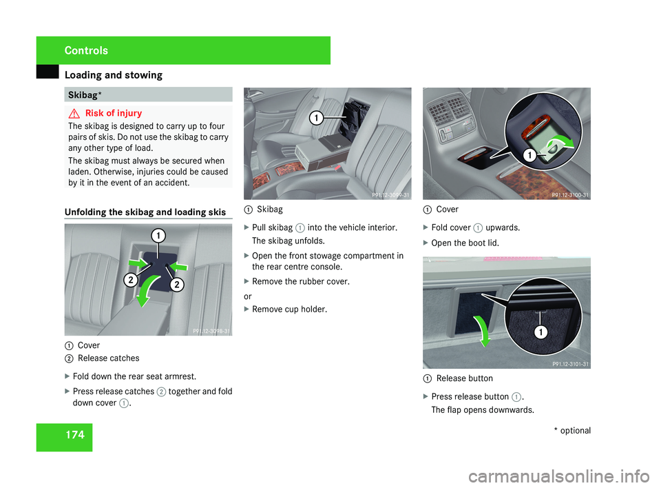
Unfolding the skibag and loading skis 1
Cover
2 Release catches
X Fold down the rear seat armrest.
X Press release catches 2 together and fold
down cover 1. 1
Skibag
X Pull skibag 1 into the vehicle interior.
The skibag unfolds.
X Open the front stowage compartment in
the rear centre console.
X Remove the rubber cover.
or
X Remove cup holder. 1
Cover
X Fold cover 1 upwards.
X Open the boot lid. 1
Release button
X Press release button 1.
The flap opens downwards. Controls
* optional
219_AKB; 2; 4, en-GB
mkalafa,
2007-11-13T09:28:36+01:00 - Seite 174
Page 178 of 329
Loading and stowing
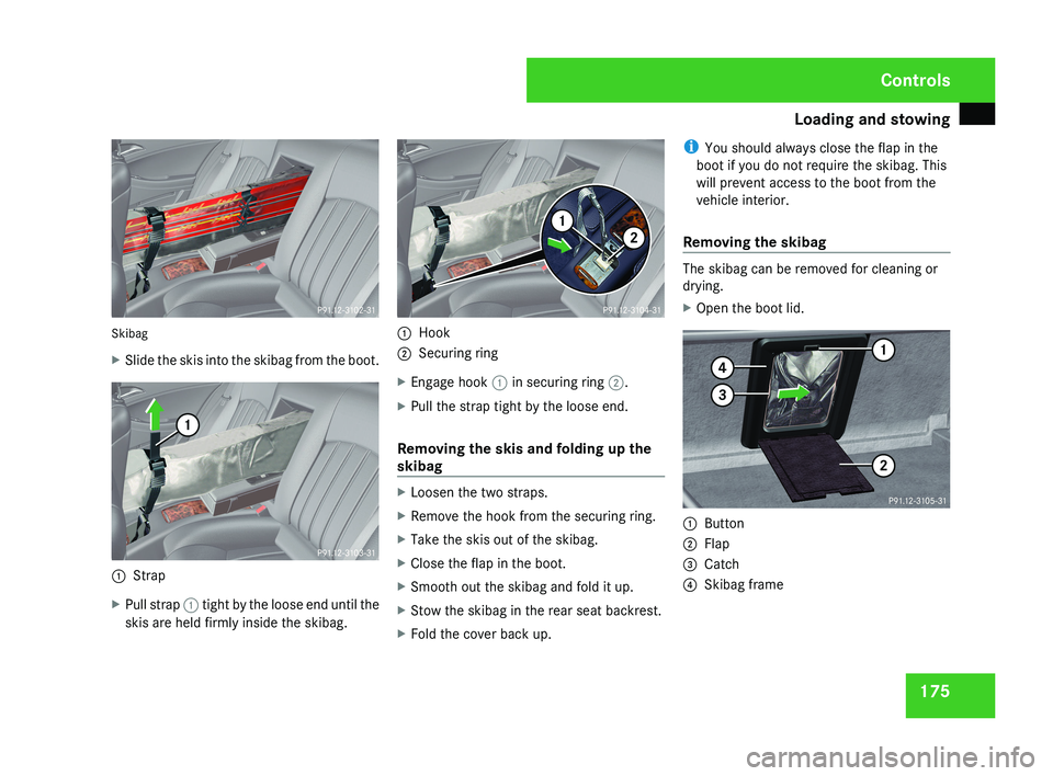
175Skibag
X
Slide the skis into the skibag from the boot.
1 Strap
X Pull strap 1 tight by the loose end until the
skis are held firmly inside the skibag.
1 Hook
2 Securing ring
X Engage hook 1 in securing ring 2.
X Pull the strap tight by the loose end.
Removing the skis and folding up the
skibag
X Loosen the two straps.
X Remove the hook from the securing ring.
X Take the skis out of the skibag.
X Close the flap in the boot.
X Smooth out the skibag and fold it up.
X Stow the skibag in the rear seat backrest.
X Fold the cover back up. i
You should always close the flap in the
boot if you do not require the skibag. This
will prevent access to the boot from the
vehicle interior.
Removing the skibag
The skibag can be removed for cleaning or
drying.
X Open the boot lid.
1 Button
2 Flap
3 Catch
4 Skibag frame
Controls
219_AKB; 2; 4, en-GB
mkalafa,
2007-11-13T09:28:36+01:00 - Seite 175
Page 179 of 329
Loading and stowing
176
X
Press button 1.
Flap 2 folds down.
X Press catch 3 in and pull out frame 4
containing the skibag. G
Risk of poisoning
When the skibag has been removed, always
drive with the boot lid closed. Exhaust
fumes could otherwise enter the vehicle
interior. Luggage net in the front-passenger
footwell
G
Risk of injury
Only place lightweight items in the luggage
net. Do not use it to transport heavy, bulky,
sharp-edged or fragile objects. In the event
of an accident, the luggage net will not
secure the transported goods. Loading guidelines
G
Risk of injury
Secure and position the load as described
in the loading guidelines.
Even if you follow all the loading guidelines,
the load will increase the risk of injury in the
event of an accident. G
Risk of poisoning
Keep the boot lid closed while the vehicle
is in operation. Otherwise, exhaust fumes
could enter the vehicle interior and poison
you.
The handling characteristics of a laden vehi-
cle are dependent on the distribution of the
load within the vehicle. You should therefore
load your vehicle as shown in the illustrations.
Observe the following notes when transport-
ing a load:
R When transporting a load, never exceed the
maximum permissible gross vehicle weight
or the permissible axle loads for the vehicle
(including occupants).
R Position heavy loads as far forwards and as
low in the boot as possible.
R The load must not protrude above the
upper edge of the backrests. R
Always place the load against the front or
rear seat backrests.
R Secure the load with sufficiently strong and
wear-resistant load restraints. Pad sharp
edges for protection.
i Load restraints are available at any quali-
fied specialist workshop, e.g. a Mercedes-
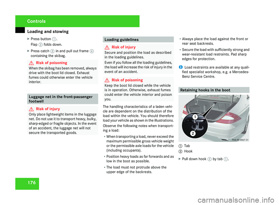
Benz Service Centre. Retaining hooks in the boot1
Tab
2 Hook
X Pull down hook 2 by tab 1.
Controls
219_AKB; 2; 4, en-GB
mkalafa,
2007-11-13T09:28:36+01:00 - Seite 176