2008 MERCEDES-BENZ CLS COUPE tow
[x] Cancel search: towPage 289 of 329

Flat tyre
286
X
Screw union nut 5 on air hose 4 onto the
valve.
X Insert plug 3 into the cigarette lighter
socket* ( Y page 181) or into a 12V socket
in your vehicle ( Y page 182).
X Make sure that the key is in position 2 in
the ignition lock.
X Press on/off switch 2 on the electric air
pump to I.
The electric air pump is switched on. The
tyre is inflated.
X When a tyre pressure of 3.5 bar has been
reached, press 0 on the electric air pump
switch.
The electric air pump is switched off.
! Do not operate the electric air pump for
longer than six minutes without a break.
Otherwise, it may overheat.
The air pump can be operated again once
it has cooled down.
If the tyre pressure is higher than 3.5 bar: X
Open the pressure release screw on the
pressure gauge until the tyre pressure is
correct.
X Disconnect the electric air pump and stow
it away.
Lowering the vehicle X
Lower the vehicle. To do this, turn the crank
of the jack anti-clockwise until the vehicle
is standing firmly on the ground again.
X Place the jack to one side. 1
– 5 Wheel bolts
X Tighten the wheel bolts evenly in a cross-
wise pattern in the sequence indica-
ted ( 1 to 5). The tightening torque must
be 130 Nm. G
Risk of accident
Have the tightening torque checked imme-
diately after a wheel is changed. The wheels
could work loose if they are not tightened
to a tightening torque of 130 Nm.
X Turn the jack back to its initial position and
store it and the rest of the vehicle tool kit
in the boot.
Vehicles with the "Minispare"/collapsible
emergency spare wheel*:
X Wrap the faulty wheel in the protective film
provided with the "Minispare"/collapsible
emergency spare wheel* and transport the
wheel in the boot.
or
X Depending on the size of the wheel, the
faulty wheel may also be secured in the
spare wheel recess. In this case, the stow-
age well casing will have to be removed
from the spare wheel well and stowed in the
boot.
i Do not activate the tyre pressure moni-
tor* until the deflated tyre has been
removed from the vehicle. Practical advice
* optional
219_AKB; 2; 4, en-GB
mkalafa,
2007-11-13T09:28:36+01:00 - Seite 286
Page 296 of 329

Towing and tow-starting
293Towing and tow-starting
Points to remember
G
Risk of accident
If you tow the vehicle, you must use a rigid
towing bar if:
R the engine is not running
R there is a brake system malfunction
R the voltage supply or the vehicle's elec-
trical system is damaged
There
is no power assistance for the steer-
ing when the engine is not running. G
Risk of accident
The vehicle is braked when HOLD is activa-
ted.
Therefore, deactivate HOLD if the vehi-
cle is to be towed.
If you tow or tow-start another vehicle, its
weight must not exceed the maximum per-
missible gross vehicle weight of your vehi-
cle.
It is better to have the vehicle transported
than to have it towed.
When towing, observe the legal requirements
in all countries concerned. !
When towing, pull away slowly and with-
out
jerking. If the tractive power is too high,
the vehicles could be damaged. Do not use
the towing eye for recovery.
! You may tow the vehicle for a maximum
of 50 km. A towing speed of 50 km/h must
not be exceeded.
With towing distances over 50 km, the
entire vehicle needs to be lifted up and
transported.
! Only secure the tow cable or towing bar
to the towing eyes. You may otherwise
damage the vehicle.
R Vehicles with an automatic transmission
must not be tow-started.
R If the engine does not start, try jump-start-
ing it (Y page 291).
R If it is not possible to jump-start the vehicle,
have it towed to the nearest qualified spe-
cialist workshop, e.g. a Mercedes-Benz
Service Centre.
R If the vehicle has suffered transmission
damage, only tow it with the propeller shaft
disconnected.
R The selector lever must be in position N on
vehicles with automatic transmission. R
If you are towing the vehicle over a consid-
erable distance, this may only be done with
the rear axle raised.
R The ignition must be switched off if you are
towing the vehicle with the front/rear axle
raised. Intervention by ESP ®
could other-
wise damage the brake system.
R Before towing the vehicle, make sure that
the battery is connected and charged. Oth-
erwise:
-You cannot switch on the ignition
- You cannot move the selector lever to N
- You have no support when braking
i Switch off the automatic locking feature
before the vehicle is towed (Y page 127).
You could otherwise be locked out when
pushing or towing the vehicle. Practical advice
219_AKB; 2; 4, en-GB
mkalafa,
2007-11-13T09:28:36+01:00 - Seite 293
Page 297 of 329

Towing and tow-starting
294 Fitting the towing eye
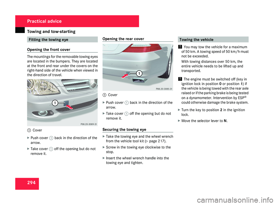
Opening the front cover The mountings for the removable towing eyes
are located in the bumpers. They are located
at the front and rear under the covers on the
right-hand side of the vehicle when viewed in
the direction of travel.
1
Cover
X Push cover 1 back in the direction of the
arrow.
X Take cover 1 off the opening but do not
remove it. Opening the rear cover
1
Cover
X Push cover 1 back in the direction of the
arrow.
X Take cover 1 off the opening but do not
remove it.
Securing the towing eye X
Take the towing eye and the wheel wrench
from the vehicle tool kit ( Y page 217).
X Screw in the towing eye clockwise to the
stop.
X Insert the wheel wrench handle into the
towing eye and tighten. Towing the vehicle
! You may tow the vehicle for a maximum
of 50 km. A towing speed of 50 km/h must
not be exceeded.
With towing distances over 50 km, the
entire vehicle needs to be lifted up and
transported.
! The engine must be switched off (key in
ignition lock in position 0 or position 1) if
the vehicle is being towed with the rear axle
raised or if the parking brake is being tested
on a dynamometer. Intervention by ESP ®
could otherwise damage the brake system.
X Turn the key to position 2 in the ignition
lock.
X Move the selector lever to N. Practical advice
219_AKB; 2; 4, en-GB
mkalafa,
2007-11-13T09:28:36+01:00 - Seite 294
Page 298 of 329

Fuses
295Removing the towing eye
X Take the wheel wrench from the vehicle
tool kit ( Y page 217).
X Insert the wheel wrench handle into the
towing eye and turn it anti-clockwise.
X Unscrew the towing eye.
X Replace the cover and press it until it
engages.
X Return the towing eye and the wheel
wrench to the vehicle tool kit. Transporting the vehicle
The towing eyes can be used to pull the vehi-
cle onto a trailer or transporter for transport-
ing purposes.
! Only lash the vehicle down by the wheels
or wheel rims, not by parts of the vehicle
such as axle or steering components. The
vehicle could otherwise be damaged.
X Turn the key to position 2 in the ignition
lock.
X Move the selector lever to N. Fuses
Notes on changing fuses
The
fuses in your vehicle serve to close down
faulty circuits. If a fuse blows, all the compo-
nents on the circuit and their functions will
fail.
i Blown fuses must be replaced with fuses
of the same rating (which can be recog-
nised by the colour and amperage) and
which have the amperage specified in the
fuse allocation chart. A Mercedes-Benz
Service Centre will be happy to advise you. G
Risk of fire
Only use fuses that have been approved for
Mercedes-Benz vehicles and which have
the correct amperage for the system con-
cerned. Do not attempt to repair or bridge
faulty
fuses. A circuit overload could other-
wise cause a fire. Have the cause traced
and rectified at a qualified specialist work-
shop, e.g. a Mercedes-Benz Service Centre.
If the newly inserted fuse also blows, have the
cause traced and rectified at a qualified spe-
cialist workshop, e.g. a Mercedes-Benz
Service Centre. !
Only use fuses that have been approved
for Mercedes-Benz vehicles and which
have the correct amperage for the system
concerned.
Otherwise, components or sys-
tems could be damaged.
The fuses are located in various fuse boxes:
R Main fuse box on the driver's side of the
dashboard
R Fuse box in the boot, on the left-hand side
of the vehicle
Fuse allocation chart The fuse allocation chart is in the main fuse
box in the dashboard. The fuse amperage is
also indicated there. Practical advice
219_AKB; 2; 4, en-GB
mkalafa,
2007-11-13T09:28:36+01:00 - Seite 295