Page 1937 of 4083
DAYTIME LIGHT SYSTEMEXL-9
< FUNCTION DIAGNOSIS >
C
DE
F
G H
I
J
K
M A
B
EXL
N
O P
DAYTIME LIGHT SYSTEM
System DiagramINFOID:0000000001547098
System DescriptionINFOID:0000000001547099
The headlamp system for Canada vehicles is equipped with a daytime light control unit that activates the high
beam headlamps at approximately half illumination whenever the engine is operating. If the parking brake is
applied before the engine is started the daytime lights will not be illuminated. The daytime lights will illuminate
once the parking brake is released. Thereafter, the daytime lights will continue to operate when the parking
brake is applied.
Component Parts LocationINFOID:0000000001547100
AWLIA0010GB
ALLIA0380ZZ
Revision: March 2010 2008 QX56
Page 1939 of 4083
AUTO LIGHT SYSTEMEXL-11
< FUNCTION DIAGNOSIS >
C
DE
F
G H
I
J
K
M A
B
EXL
N
O P
AUTO LIGHT SYSTEM
System DiagramINFOID:0000000001547102
System DescriptionINFOID:0000000001547103
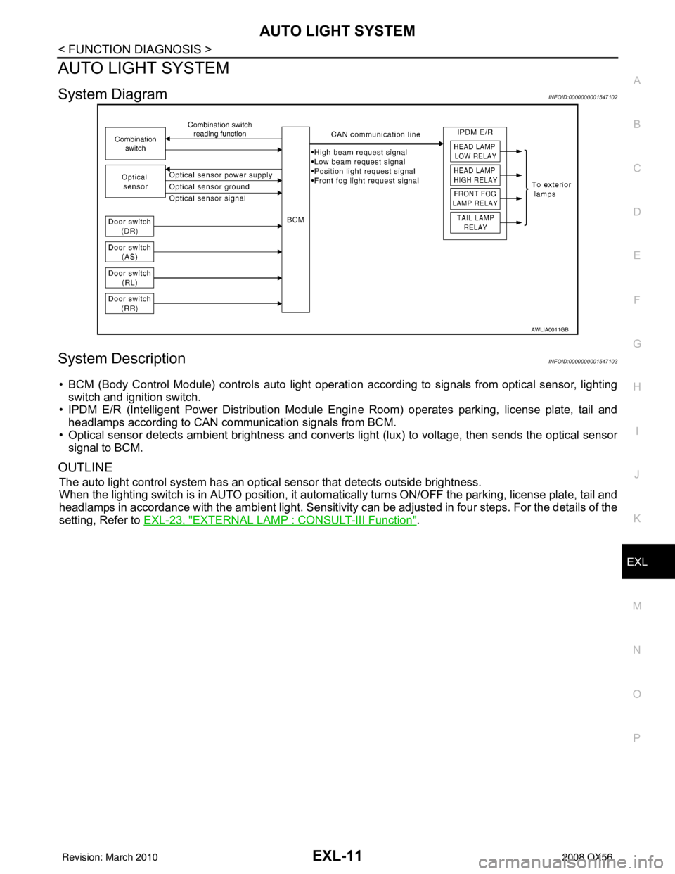
• BCM (Body Control Module) controls auto light operati on according to signals from optical sensor, lighting
switch and ignition switch.
• IPDM E/R (Intelligent Power Distribution Module Engine Room) operates parking, license plate, tail and
headlamps according to CAN communication signals from BCM.
• Optical sensor detects ambient br ightness and converts light (lux) to voltage, then sends the optical sensor
signal to BCM.
OUTLINE
The auto light control system has an optical sensor that detects outside brightness.
When the lighting switch is in AUTO position, it automat ically turns ON/OFF the parking, license plate, tail and
headlamps in accordance with the ambient light. Sensitivity can be adjusted in four steps. For the details of the
setting, Refer to EXL-23, "
EXTERNAL LAMP : CONSULT-III Function".
AWLIA0011GB
Revision: March 2010 2008 QX56
Page 1942 of 4083
EXL-14
< FUNCTION DIAGNOSIS >
HEADLAMP AIMING SYSTEM (MANUAL)
HEADLAMP AIMING SYSTEM (MANUAL)
System DiagramINFOID:0000000001806201
System DescriptionINFOID:0000000001806202
The headlamp aiming system (manual) controls the headlamp light axis height according to input from the
headlamp aiming switch. The variable internal resist ance of the headlamp aiming switch controls the signal
ground of the headlamp aiming motors located on the front combination lamp LH and RH.
Component DescriptionINFOID:0000000001806204
AWLIA1629GB
Part Description
Headlamp aiming motor Moves the headlamp up/down based on input from the headlamp aiming switch.
Headlamp aiming switch Controls variable ground to the headlamp aiming motor signal to move the headlamp aim-
ing motor up/down.
Revision: March 2010
2008 QX56
Page 1943 of 4083
FRONT FOG LAMPEXL-15
< FUNCTION DIAGNOSIS >
C
DE
F
G H
I
J
K
M A
B
EXL
N
O P
FRONT FOG LAMP
System DiagramINFOID:0000000001547106
System DescriptionINFOID:0000000001547107
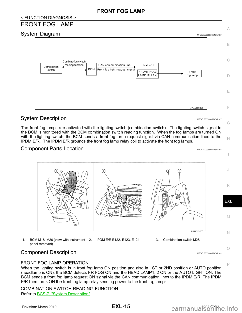
The front fog lamps are activated with the lighting switch (combination switch). The lighting switch signal to
the BCM is monitored with the BCM combination switch reading function. When the fog lamps are turned ON
with the lighting switch, the BCM sends a front fog lamp request signal via CAN communication lines to the
IPDM E/R. The IPDM E/R grounds the front fog la mp relay coil to activate the front fog lamps.
Component Parts LocationINFOID:0000000001547108
Component DescriptionINFOID:0000000001547109
FRONT FOG LAMP OPERATION
When the lighting switch is in front fog lamp ON posit ion and also in 1ST or 2ND position or AUTO position
(headlamp is ON), the BCM detects FR FOG ON and t he HEAD LAMP1, 2 ON or the AUTO LIGHT ON. The
BCM sends a front fog lamp request ON signal via the CAN communication lines to the IPDM E/R. The IPDM
E/R then turns ON the front fog lamp re lay sending power to the front fog lamps.
COMBINATION SWITCH READING FUNCTION
Refer to BCS-7, "System Description".
JPLIA0004GB
1. BCM M18, M20 (view with instrument
panel removed) 2. IPDM E/R E122, E123, E124 3. Combination switch M28
ALLIA0379ZZ
Revision: March 2010
2008 QX56
Page 1944 of 4083
EXL-16
< FUNCTION DIAGNOSIS >
TURN SIGNAL AND HAZARD WARNING LAMPS
TURN SIGNAL AND HAZARD WARNING LAMPS
System DiagramINFOID:0000000001547110
System DescriptionINFOID:0000000001547111
TURN SIGNAL OPERATION
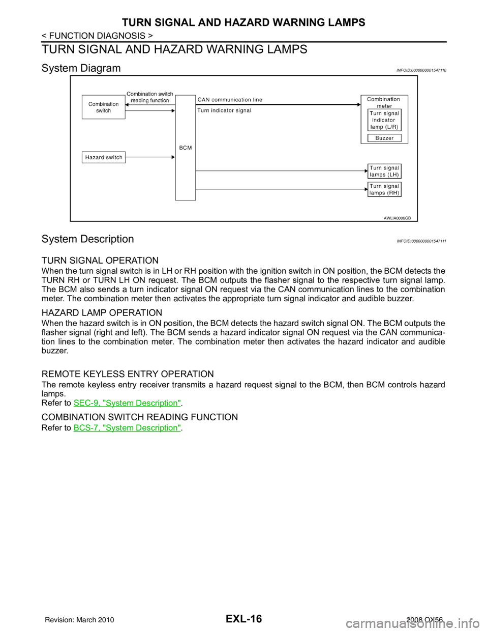
When the turn signal switch is in LH or RH position with the ignition switch in ON position, the BCM detects the
TURN RH or TURN LH ON request. The BCM outputs the flasher signal to the respective turn signal lamp.
The BCM also sends a turn indicator signal ON reques t via the CAN communication lines to the combination
meter. The combination meter then activates the appropriate turn signal indicator and audible buzzer.
HAZARD LAMP OPERATION
When the hazard switch is in ON position, the BCM det ects the hazard switch signal ON. The BCM outputs the
flasher signal (right and left). The BCM sends a hazar d indicator signal ON request via the CAN communica-
tion lines to the combination meter. The combination meter then activates the hazard indicator and audible
buzzer.
REMOTE KEYLESS ENTRY OPERATION
The remote keyless entry receiver transmits a hazar d request signal to the BCM, then BCM controls hazard
lamps.
Refer to SEC-9, "
System Description".
COMBINATION SWITCH READING FUNCTION
Refer to BCS-7, "System Description".
AWLIA0006GB
Revision: March 2010 2008 QX56
Page 1946 of 4083
EXL-18
< FUNCTION DIAGNOSIS >
PARKING, LICENSE PLATE AND TAIL LAMPS
PARKING, LICENSE PLATE AND TAIL LAMPS
System DiagramINFOID:0000000001547114
System DescriptionINFOID:0000000001547115
PARKING, LICENCE PLATE AND TAIL LAMPS OPERATION
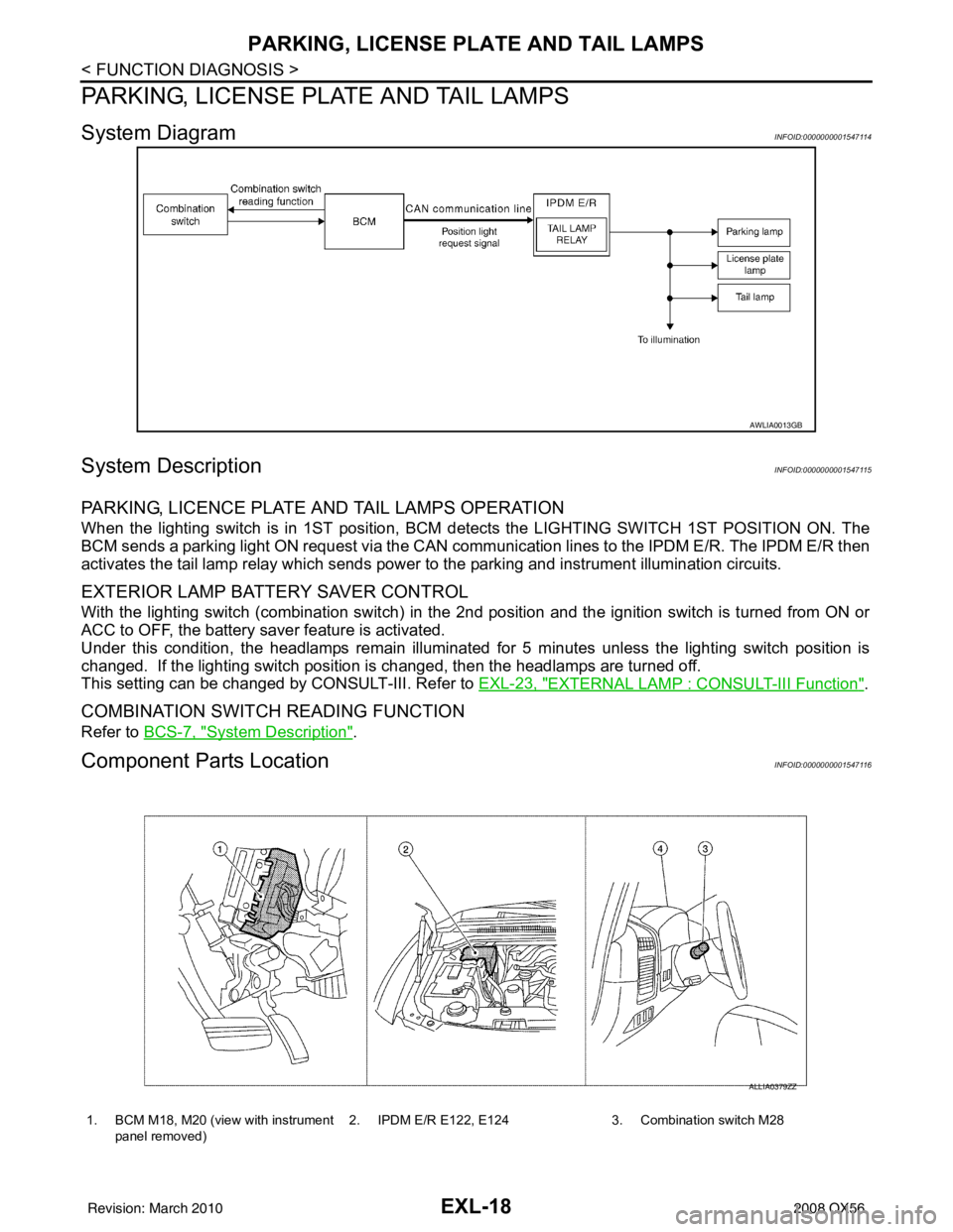
When the lighting switch is in 1ST position, BCM detects the LIGHTI NG SWITCH 1ST POSITION ON. The
BCM sends a parking light ON request via the CAN comm unication lines to the IPDM E/R. The IPDM E/R then
activates the tail lamp relay which sends power to the parking and instrument illumination circuits.
EXTERIOR LAMP BATTERY SAVER CONTROL
With the lighting switch (combination switch) in the 2nd position and the ignition switch is turned from ON or
ACC to OFF, the battery saver feature is activated.
Under this condition, the headlamps remain illuminated for 5 minutes unless the lighting switch position is
changed. If the lighting switch position is changed, then the headlamps are turned off.
This setting can be changed by CONSULT-III. Refer to EXL-23, "
EXTERNAL LAMP : CONSULT-III Function".
COMBINATION SWITCH READING FUNCTION
Refer to BCS-7, "System Description".
Component Parts LocationINFOID:0000000001547116
AWLIA0013GB
1. BCM M18, M20 (view with instrument
panel removed) 2. IPDM E/R E122, E124 3. Combination switch M28
ALLIA0379ZZ
Revision: March 2010
2008 QX56
Page 1948 of 4083
EXL-20
< FUNCTION DIAGNOSIS >
TRAILER TOW
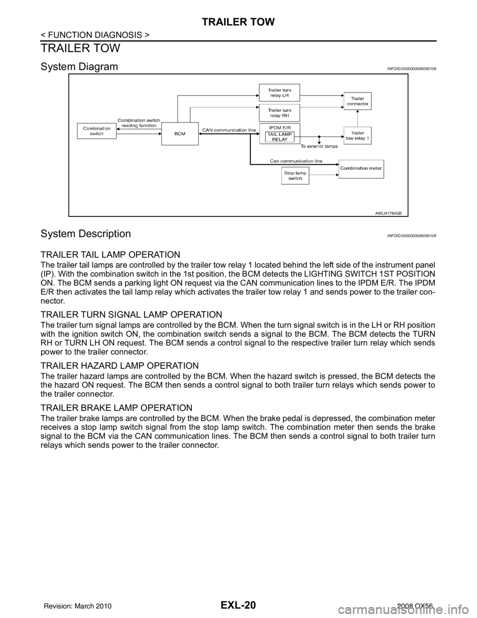
TRAILER TOW
System DiagramINFOID:0000000006095108
System DescriptionINFOID:0000000006095109
TRAILER TAIL LAMP OPERATION
The trailer tail lamps are controlled by the trailer tow relay 1 located behind the left side of the instrument panel
(IP). With the combination switch in the 1st position, the BCM detects the LIGHTING SWITCH 1ST POSITION
ON. The BCM sends a parking light ON request via the CAN communication lines to the IPDM E/R. The IPDM
E/R then activates the tail lamp relay which activates the trailer tow relay 1 and sends power to the trailer con-
nector.
TRAILER TURN SIGNAL LAMP OPERATION
The trailer turn signal lamps are controlled by the BCM. When the turn signal switch is in the LH or RH position
with the ignition switch ON, the combination switch sends a signal to the BCM. The BCM detects the TURN
RH or TURN LH ON request. The BCM sends a control signal to the respective trailer turn relay which sends
power to the trailer connector.
TRAILER HAZARD LAMP OPERATION
The trailer hazard lamps are controlled by the BCM. W hen the hazard switch is pressed, the BCM detects the
the hazard ON request. The BCM then sends a control si gnal to both trailer turn relays which sends power to
the trailer connector.
TRAILER BRAKE LAMP OPERATION
The trailer brake lamps are controlled by the BCM. When the brake pedal is depressed, the combination meter
receives a stop lamp switch signal from the stop lamp switch. The combination meter then sends the brake
signal to the BCM via the CAN communication lines. The BCM then sends a control signal to both trailer turn
relays which sends power to the trailer connector.
AWLIA1764GB
Revision: March 2010 2008 QX56
Page 1971 of 4083
HEADLAMPEXL-43
< COMPONENT DIAGNOSIS >
C
DE
F
G H
I
J
K
M A
B
EXL
N
O P
HEADLAMP
Wiring Diagram INFOID:0000000001547143
AALWA0085GB
Revision: March 2010 2008 QX56