Page 2265 of 4083
HAC-12
< FUNCTION DIAGNOSIS >[AUTOMATIC AIR CONDITIONER]
AUTOMATIC AIR CONDITIONER SYSTEM
AUTOMATIC AIR CONDITIONER SYSTEM
Control System DiagramINFOID:0000000001679770
CONTROL SYSTEM
The control system consists of
input sensors, switches, the A/C auto amp.(microcomputer) and outputs.
The relationship of these components is shown in the figure below:
Control System DescriptionINFOID:0000000001679771
CONTROL OPERATION
AWIIA0088GB
Revision: March 2010 2008 QX56
Page 2345 of 4083
HAC-92
< ECU DIAGNOSIS >[AUTOMATIC AIR CONDITIONER]
AIR CONDITIONER CONTROL
Wiring Diagram
INFOID:0000000001679828
AAIWA0062GB
Revision: March 2010 2008 QX56
Page 2377 of 4083
HRN-1
DRIVER CONTROLS
C
DE
F
G H
I
J
K
M
SECTION HRN
A
B
HRN
N
O P
CONTENTS
HORN
PRECAUTION ....... ........................................2
PRECAUTIONS .............................................. .....2
Precaution for Supplemental Restraint System
(SRS) "AIR BAG" and "SEAT BELT PRE-TEN-
SIONER" ............................................................. ......
2
Precaution Necessary for Steering Wheel Rota-
tion After Battery Disconnect ............................... ......
2
COMPONENT DIAGNOSIS ..........................4
HORN .................................................................4
Wiring Diagram .................................................... .....4
REMOVAL AND INSTALLATION ................7
HORN .................................................................7
Removal and Installation ..................................... .....7
Revision: March 2010 2008 QX56
Page 2380 of 4083
HRN-4
< COMPONENT DIAGNOSIS >
HORN
COMPONENT DIAGNOSIS
HORN
Wiring DiagramINFOID:0000000001737093
AALWA0084GB
Revision: March 20102008 QX56
Page 2384 of 4083

INL-1
DRIVER CONTROLS
C
DE
F
G H
I
J
K
M
SECTION INL
A
B
INL
N
O P
CONTENTS
INTERIOR LIGHTING SYSTEM
BASIC INSPECTION ....... .............................3
DIAGNOSIS AND REPAIR WORKFLOW ..... .....3
Work Flow ........................................................... ......3
FUNCTION DIAGNOSIS ...............................6
INTERIOR ROOM LAMP CONTROL SYSTEM
.....
6
System Diagram .................................................. ......6
System Description ...................................................6
Component Parts Location ........................................7
Component Description .............................................8
ILLUMINATION CONTROL SYSTEM .................9
System Diagram .................................................. ......9
System Description ...................................................9
Component Parts Location ........................................9
Component Description ...........................................10
DIAGNOSIS SYSTEM (BCM) ............................11
COMMON ITEM ..................................................... ....11
COMMON ITEM : CONSULT-III Function ...............11
INT LAMP .............................................................. ....11
INT LAMP : CONSULT-III Function ........................11
BATTERY SAVER ................................................. ....13
BATTERY SAVER : CONSULT-III Function ...........13
COMPONENT DIAGNOSIS .........................14
POWER SUPPLY AND GROUND CIRCUIT .. ....14
BCM ....................................................................... ....14
BCM : Inspection Procedure ...................................14
INTERIOR ROOM LAMP POWER SUPPLY
CIRCUIT ......................................................... ....
15
Description .......................................................... ....15
Component Function Check ....................................15
Diagnosis Procedure ...............................................15
INTERIOR ROOM LAMP CONTROL CIRCUIT
...
17
Description ........................................................... ....17
Component Function Check ....................................17
Diagnosis Procedure ...............................................17
STEP LAMP CIRCUIT .......................................19
Description ........................................................... ....19
Component Function Check ....................................19
Diagnosis Procedure ...............................................19
CARGO LAMP CONTROL CIRCUIT ................21
Description ...............................................................21
Component Function Check ....................................21
Diagnosis Procedure ...............................................21
IGNITION KEYHOLE ILLUMINATION CON-
TROL CIRCUIT .................................................
23
Description ...............................................................23
Component Function Check ....................................23
Diagnosis Procedure ...............................................23
INTERIOR ROOM LAMP CONTROL SYSTEM
...
25
Wiring Diagram .................................................... ....25
ILLUMINATION .................................................41
Wiring Diagram ........................................................41
ECU DIAGNOSIS .........................................55
BCM (BODY CONTROL MODULE) .................55
Description ........................................................... ....55
SYMPTOM DIAGNOSIS ..............................56
INTERIOR LIGHTING SYSTEM SYMPTOMS ...56
Symptom Table ................................................... ....56
PRECAUTION ..............................................57
PRECAUTIONS .................................................57
Revision: March 2010 2008 QX56
Page 2389 of 4083

INL-6
< FUNCTION DIAGNOSIS >
INTERIOR ROOM LAMP CONTROL SYSTEM
FUNCTION DIAGNOSIS
INTERIOR ROOM LAMP CONTROL SYSTEM
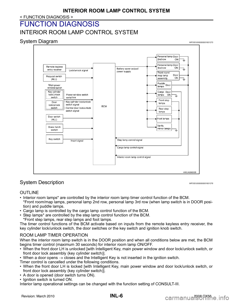
System DiagramINFOID:0000000001601375
System DescriptionINFOID:0000000001601376
OUTLINE
• Interior room lamps* are controlled by the interior room lamp timer control function of the BCM.
*Front room/map lamps, personal lamp 2nd row, personal lamp 3rd row (when lamp switch is in DOOR posi-
tion) and puddle lamps.
• Cargo lamp is controlled by the cargo lamp control function of the BCM.
• Step lamps* are controlled by the step lamp control function of the BCM. *Front step lamps, rear step lamps and foot lamps.
The timer control functions of the BCM activate based on inputs from the remote keyless entry receiver, the
key cylinder lock/unlock switch, the door switc hes or the key switch and ignition knob switch.
ROOM LAMP TIMER OPERATION
When the interior room lamp switch is in the DOOR position and when all conditions below are met, the BCM
begins timer control (maximum 30 seconds) for interior room lamp ON/OFF.
• When the front door LH is unlocked [with Intelligent Key, main power window and door lock/unlock switch, or
front door lock assembly (key cylinder switch)].
• When a door opens → closes and the Intelligent Key is not inserted in the ignition switch.
Timer control is cancelled under the following conditions.
• When the front door LH is locked [with Intelligent Key, main power window and door lock/unlock switch, or
front door lock assembly (key cylinder switch)].
• A door is opened (door switch turns ON).
• Ignition switch is turned ON.
Interior lamp operational settings can be c hanged with the function setting of CONSULT-III.
AWLIA0965GB
Revision: March 2010 2008 QX56
Page 2392 of 4083

ILLUMINATION CONTROL SYSTEMINL-9
< FUNCTION DIAGNOSIS >
C
DE
F
G H
I
J
K
M A
B
INL
N
O P
ILLUMINATION CONTROL SYSTEM
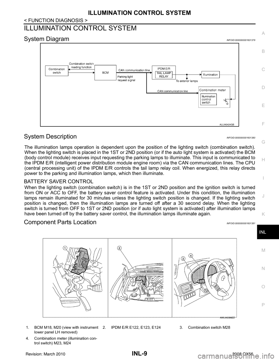
System DiagramINFOID:0000000001601379
System DescriptionINFOID:0000000001601380
The illumination lamps operation is dependent upon the posit ion of the lighting switch (combination switch).
When the lighting switch is placed in the 1ST or 2ND posit ion (or if the auto light system is activated) the BCM
(body control module) receives input requesting the park ing lamps to illuminate. This input is communicated to
the IPDM E/R (intelligent power distribution module engine room) via the CAN communication lines. The CPU
(central processing unit) of the IPDM E/R controls the tail lamp relay coil. When energized, this relay directs
power to the parking and illumination lamps, which then illuminate.
BATTERY SAVER CONTROL
When the lighting switch (combination switch) is in t he 1ST or 2ND position and the ignition switch is turned
from ON or ACC to OFF, the battery saver control feat ure is activated. Under this condition, the illumination
lamps remain illuminated for 30 minutes unless the light ing switch position is changed. If the lighting switch
position is changed, then the illumination lamps are turned off after a 30 second delay. When the lighting
switch is turned from OFF to 1ST or 2ND position (or if auto light system is activated) after illumination lamps
have been turned off by the battery saver control, the illumination lamps illuminate again.
Component Parts LocationINFOID:0000000001601381
ALLIA0424GB
1. BCM M18, M20 (view with instrument
lower panel LH removed) 2. IPDM E/R E122, E123, E124 3. Combination switch M28
4. Combination meter (illumination con- trol switch) M23, M24
AWLIA0398ZZ
Revision: March 2010 2008 QX56
Page 2408 of 4083
INTERIOR ROOM LAMP CONTROL SYSTEMINL-25
< COMPONENT DIAGNOSIS >
C
DE
F
G H
I
J
K
M A
B
INL
N
O P
INTERIOR ROOM LAMP CONTROL SYSTEM
Wiring DiagramINFOID:0000000001601402
AALWA0091GB
Revision: March 2010 2008 QX56