2008 INFINITI QX56 diagram
[x] Cancel search: diagramPage 2153 of 4083
HOW TO READ WIRING DIAGRAMSGI-11
< HOW TO USE THIS MANUAL >
C
DE
F
G H
I
J
K L
M B
GI
N
O P
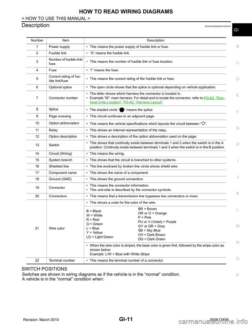
DescriptionINFOID:0000000001539192
SWITCH POSITIONS
Switches are shown in wiring diagrams as if the vehicle is in the “normal” condition.
A vehicle is in the “normal” condition when:
Number Item Description
1 Power supply • This means the power supply of fusible link or fuse.
2 Fusible link • “X” means the fusible link.
3 Number of fusible link/
fuse • This means the number of fusible link or fuse location.
4 Fuse • “/” means the fuse.
5 Current rating of fus-
ible link/fuse • This means the current rating of the fusible link or fuse.
6 Optional splice • The open circle shows that the splice is optional depending on vehicle application.
7 Connector number • The letter shows which harness the connector is located in.
• Example “M”: main harness. For detail and to locate the connector, refer to
PG-62, "
Elec-
trical Units Location", PG-40, "Harness Layout".
8Splice • The shaded circle “ ” means the splice.
9 Page crossing • This circuit continues to an adjacent page.
10 Option abbreviation • This means the vehicle specifications which layouts the circuit between “ ”.
11 Relay • This shows an internal representation of the relay.
12 Option description • This shows a description of the option abbreviation used on the page.
13 Switch • This shows that continuity exists between terminals 1 and 2 when the switch is in the A
position. Continuity exists between terminals 1 and 3 when the switch is in the B position.
14 Circuit (Wiring) • This means the wiring.
15 System branch • This shows that the circuit is branched to other systems.
16 Shielded line • The line enclosed by broken line circle shows shield wire.
17 Component name • This shows the name of a component.
18 Ground (GND) • This shows the ground connection.
19 Connector • This means the connector information.
• This unit-side is described by the connector symbols.
20 Connectors • This means that a transmission line bypasses two connectors or more.
21 Wire color • This shows a code for the color of the wire.
B = Black
W = White
R = Red
G = Green
L = Blue
Y = Yellow
LG = Light Green BR = Brown
OR or O = Orange
P = Pink
PU or V (Violet) = Purple
GY or GR = Gray
SB = Sky Blue
CH = Dark Brown
DG = Dark Green
• When the wire color is striped, the base color is given first, followed by the stripe color as shown below:
Example: L/W = Blue with White Stripe
22 Terminal number • This means the terminal number of a connector.
Revision: March 2010 2008 QX56
Page 2154 of 4083
GI-12
< HOW TO USE THIS MANUAL >
HOW TO READ WIRING DIAGRAMS
• ignition switch is “OFF”,
• doors, hood and trunk lid/back door are closed,
• pedals are not depressed, and
• parking brake is released.
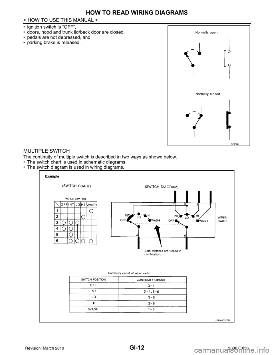
MULTIPLE SWITCH
The continuity of multiple switch is described in two ways as shown below.
• The switch chart is used in schematic diagrams.
• The switch diagram is used in wiring diagrams.
SGI860
JSAIA0017GB
Revision: March 20102008 QX56
Page 2163 of 4083
IDENTIFICATION INFORMATIONGI-21
< FEATURES OF NEW MODEL >
C
DE
F
G H
I
J
K L
M B
GI
N
O P
Identification NumberINFOID:0000000001559940
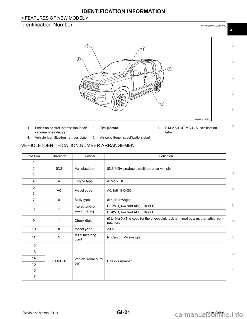
VEHICLE IDENTIFICATION NUMBER ARRANGEMENT
1. Emission control information label/ vacuum hose diagram 2. Tire placard 3. F.M.V.S.S./C.M.V.S.S. certification
label
4. Vehicle identification number plate 5. Air conditioner specification label
AWAIA0026GB
Position Character Qualifier Definition
1 5N3 Manufacturer 5N3: USA produced multi-purpose vehicle
2
3
4 A Engine type A: VK56DE
5 A0 Model code A0: Infiniti QX56
6
7 8 Body type 8: 4 door wagon
8D Gross vehicle
weight ratingD: 2WD, 4-wheel ABS, Class F
C: 4WD, 4-wheel ABS, Class F
9 * Check digit (0 to 9 or X) The code for the check digit is determined by a mathematical com-
putation.
10 8 Model year 2008
11 NManufacturing
plant
N: Canton Mississippi
12
XXXXXX Vehicle serial num-
ber Chassis number
13
14
15
16
17
Revision: March 2010
2008 QX56
Page 2181 of 4083
SERVICE INFORMATION FOR ELECTRICAL INCIDENTGI-39
< BASIC INSPECTION >
C
DE
F
G H
I
J
K L
M B
GI
N
O P
lowing section illustrates ways to simulate the c onditions/environment under which the owner experiences an
electrical incident.
The section is broken into the six following topics:• Vehicle vibration
• Heat sensitive
• Freezing
• Water intrusion
• Electrical load
• Cold or hot start up
Get a thorough description of the incident from the customer . It is important for simulating the conditions of the
problem.
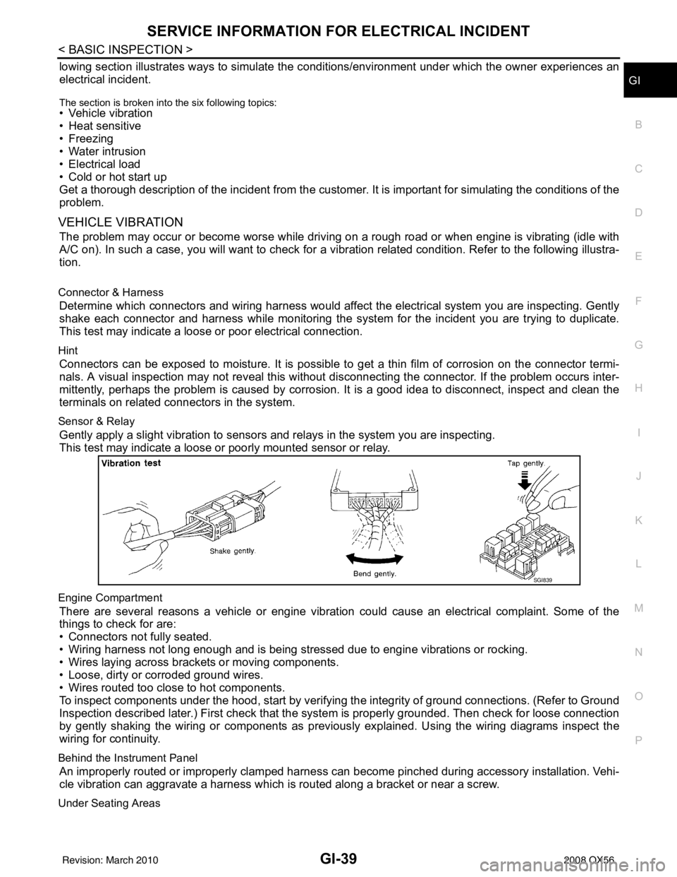
VEHICLE VIBRATION
The problem may occur or become worse while driving on a rough road or when engine is vibrating (idle with
A/C on). In such a case, you will want to check for a vibration related condition. Refer to the following illustra-
tion.
Connector & Harness
Determine which connectors and wiring harness would affect the electrical system you are inspecting. Gently
shake each connector and harness while monitoring the syst em for the incident you are trying to duplicate.
This test may indicate a loose or poor electrical connection.
Hint
Connectors can be exposed to moisture. It is possible to get a thin film of corrosion on the connector termi-
nals. A visual inspection may not reveal this without disconnecting the connector. If the problem occurs inter-
mittently, perhaps the problem is caused by corrosi on. It is a good idea to disconnect, inspect and clean the
terminals on related connectors in the system.
Sensor & Relay
Gently apply a slight vibration to sensors and relays in the system you are inspecting.
This test may indicate a loose or poorly mounted sensor or relay.
Engine Compartment
There are several reasons a vehicle or engine vibration could cause an electrical complaint. Some of the
things to check for are:
• Connectors not fully seated.
• Wiring harness not long enough and is being stressed due to engine vibrations or rocking.
• Wires laying across brackets or moving components.
• Loose, dirty or corroded ground wires.
• Wires routed too close to hot components.
To inspect components under the hood, start by verifyi ng the integrity of ground connections. (Refer to Ground
Inspection described later.) First check that the system is properly grounded. Then check for loose connection
by gently shaking the wiring or components as previous ly explained. Using the wiring diagrams inspect the
wiring for continuity.
Behind the Instrument Panel
An improperly routed or improperly clamped harness can become pinched during accessory installation. Vehi-
cle vibration can aggravate a harness which is routed along a bracket or near a screw.
Under Seating Areas
SGI839
Revision: March 2010 2008 QX56
Page 2189 of 4083
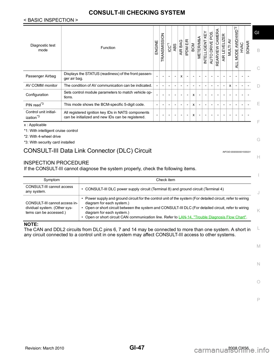
CONSULT-III CHECKING SYSTEMGI-47
< BASIC INSPECTION >
C
DE
F
G H
I
J
K L
M B
GI
N
O P
x : Applicable
*1: With intelligent cruise control
*2: With 4-wheel drive
*3: With security card installed
CONSULT-III Data Link Connector (DLC) CircuitINFOID:0000000001555031
INSPECTION PROCEDURE
If the CONSULT-III cannot diagnose the sys tem properly, check the following items.
NOTE:
The CAN and DDL2 circuits from DLC pins 6, 7 and 14 may be connected to more than one system. A short in
any circuit connected to a control unit in one system may affect CONSULT-III access to other systems.
Passenger AirbagDisplays the STATUS (readiness) of the front passen-
ger air bag. ----x-----------
AV COMM monitor The condition of AV communication can be indicated.------------x---
Configuration Sets control module parame
ters to match vehicle op-
tions. ------x---------
PIN read
*3This mode shows the BCM-specific 5-digit code. ------x---------
Control unit initial-
ization
*3All registered ignition key IDs in NATS components
can be initialized and new IDs can be registered. ------x---------
Diagnostic test
mode Function
ENGINE
TRANSMISSION
ICC
*1
ABS
AIR BAG
IPDM E/R BCM
METER/M&A
INTELLIGENT KEY
AUTO DRIVE POS.
REARVIEW CAMERA AIR LEVELIZER MULTI AV
ALL MODE AWD/4WD
*2
HVAC
SONAR
Symptom Check item
CONSULT-III cannot access
any system. • CONSULT-III DLC power supply circuit (Terminal 8) and ground circuit (Terminal 4)
CONSULT-III cannot access in-
dividual system. (Other sys-
tems can be accessed.) • Power supply and ground circuit for the control unit of the system (For detailed circuit, refer to wiring
diagram for each system.)
• Open or short circuit between the system and CONSULT-III DLC (For detailed circuit, refer to wiring diagram for each system.)
• Open or short circuit CAN communication line. Refer to LAN-14, "
Trouble Diagnosis Flow Chart".
Revision: March 2010 2008 QX56
Page 2190 of 4083
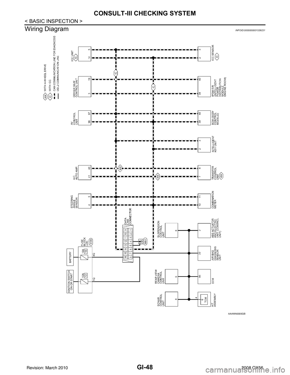
GI-48
< BASIC INSPECTION >
CONSULT-III CHECKING SYSTEM
Wiring Diagram
INFOID:0000000001539231
AAAWA0005GB
Revision: March 2010 2008 QX56
Page 2254 of 4083

HAC-1
VENTILATION, HEATER & AIR CONDITIONER
C
DE
F
G H
J
K L
M
SECTION HAC
A
B
HAC
N
O P
CONTENTS
HEATER & AIR CONDITIONING CONTROL SYSTEM
AUTOMATIC AIR CONDITIONER
BASIC INSPECTION ....... .............................
3
DIAGNOSIS AND REPAIR WORKFLOW ..... .....3
How to Perform Trouble Diagnosis For Quick And
Accurate Repair ........................................................
3
INSPECTION AND ADJUSTMENT ................ .....4
Operational Check (Front) ................................... ......4
Operational Check (Rear) .........................................5
FUNCTION DIAGNOSIS ...............................7
FUNCTION INFORMATION ........................... .....7
Component Part Location ................................... ......7
Symptom Table .........................................................9
REFRIGERATION SYSTEM ..............................11
Refrigerant Cycle ................................................ ....11
Refrigerant System Protection ................................11
AUTOMATIC AIR CONDITIONER SYSTEM . ....12
Control System Diagram ..................................... ....12
Control System Description .....................................12
Discharge Air Flow (Front) ......................................15
Discharge Air Flow (Rear) .......................................15
Switches And Their Control Function (Front) ..........17
Switches And Their Control Function (Rear) ...........18
CAN COMMUNICATION SYSTEM ....................19
System Description ............................................. ....19
DIAGNOSIS SYSTEM (HVAC) ..........................20
CONSULT-III Function (HVAC) ........................... ....20
DIAGNOSIS SYSTEM (BCM) ............................21
CONSULT-III Function (BCM) ............................. ....21
SELF-DIAGNOSIS FUNCTION ..........................22
A/C Auto Amp. Self-Diagnosis ................................22
A/C and AV Switch Asse mbly Self-Diagnosis .........22
A/C System Self-Diagnosis Code Chart .............. ....23
COMPONENT DIAGNOSIS .........................24
MODE DOOR MOTOR ......................................24
System Description .............................................. ....24
Mode Door Motor (Front) Component Function
Check ......................................................................
25
Mode Door Motor (Front) Diagnosis Procedure ......26
AIR MIX DOOR MOTOR ...................................30
System Description ..................................................30
Air Mix Door Motor Component Function Check .....31
Air Mix Door Motor (Driver) Diagnosis Procedure ....32
Air Mix Door Motor (Passenger) Diagnosis Proce-
dure .........................................................................
35
INTAKE DOOR MOTOR ...................................40
System Description ..................................................40
Intake Door Motor Component Function Check ......41
Intake Door Motor Diagnosis Procedure .................42
DEFROSTER DOOR MOTOR CIRCUIT ...........44
System Description ..................................................44
Defroster Door Motor Component Function Check
....
45
Defroster Door Motor Diagnosis Procedure ............45
BLOWER MOTOR CONTROL SYSTEM ..........49
System Description ..................................................49
Front Blower Motor Component Function Check ....50
Front Blower Motor Diagnosis Procedure ................51
Front Blower Motor Component Inspection .............54
Rear Blower Motor Description ................................55
Rear Blower Motor Component Function Check .....56
Rear Air Control (Front) Diagnosis Procedure #1 ....57
Rear Air Control (Rear) Diagnosis Procedure #2 ....58
Rear Blower Motor Component Inspection ..............59
REAR AIR CONTROL SYSTEM .......................61
Rear Air Control System Description .......................61
Rear Air Control Component Function Check .........61
Air Mix Door Motor (Rear) Diagnosis Procedure .....62
Mode Door Motor (Rear) Diagnosis Procedure .......66
Revision: March 2010 2008 QX56
Page 2255 of 4083

HAC-2
MAGNET CLUTCH ............................................71
System Description .............................................. ...71
Magnet Clutch Component Function Check ........ ...71
Magnet Clutch Diagnosis Procedure ................... ...72
WATER VALVE CIRCUIT ..................................76
Description ........................................................... ...76
Water Valve Diagnosis Procedure ..........................76
AMBIENT SENSOR ...........................................78
Component Description ....................................... ...78
Ambient Sensor Diagnosis Procedure ....................78
Ambient Sensor Component Inspection .................79
IN-VEHICLE SENSOR .......................................81
Component Description ....................................... ...81
In-Vehicle Sensor Diagnosis Procedure .................81
In-Vehicle Sensor Component Inspection ..............83
OPTICAL SENSOR ...........................................84
Component Description ..........................................84
Optical Sensor Diagnosis Procedure ......................84
INTAKE SENSOR ..............................................86
System Description .............................................. ...86
Intake Sensor Diagnosis Procedure .......................86
Intake Sensor Component Inspection ................. ...87
POWER SUPPLY AND GROUND CIRCUIT
FOR CONTROLLER ..........................................
88
Component Description ....................................... ...88
A/C Auto Amp. Component Function Check ..........88
A/C Auto Amp Power and Ground Diagnosis Pro-
cedure .....................................................................
89
ECU DIAGNOSIS .......................................90
AIR CONDITIONER CONTROL ..................... ...90
A/C Auto Amp. Terminals Reference Values ..........90
Wiring Diagram .................................................... ...92
SYMPTOM DIAGNOSIS ...........................108
AIR CONDITIONER CONTROL ..................... ..108
Symptom Matrix Chart ........................................ .108
INSUFFICIENT COOLING ................................109
Component Function Check ................................ .109
Diagnostic Work Flow ...........................................110
Performance Chart ................................................113
Trouble Diagnoses for Abnormal Pressure ...........114
INSUFFICIENT HEATING ................................117
Component Function Check .................................117
NOISE ...............................................................119
Component Function Check ................................ .119
MEMORY FUNCTION DOES NOT OPERATE ..121
Memory Function Check ...................................... .121
PRECAUTION ...........................................122
PRECAUTIONS .............................................. ..122
Precaution for Supplemental Restraint System
(SRS) "AIR BAG" and "SEAT BELT PRE-TEN-
SIONER" .............................................................. .
122
Working with HFC-134a (R-134a) ........................ .122
Precaution for Service Equipment ........................123
Revision: March 2010 2008 QX56