2008 INFINITI QX56 service reset
[x] Cancel search: service resetPage 1372 of 4083
![INFINITI QX56 2008 Factory Service Manual ON BOARD DIAGNOSTIC (OBD) SYSTEMEC-73
< FUNCTION DIAGNOSIS > [VK56DE]
C
D
E
F
G H
I
J
K L
M A
EC
NP
O
Generic Scan Tool (OBDII scan tool) complying with SAE J1978 has
8 different functions explained b INFINITI QX56 2008 Factory Service Manual ON BOARD DIAGNOSTIC (OBD) SYSTEMEC-73
< FUNCTION DIAGNOSIS > [VK56DE]
C
D
E
F
G H
I
J
K L
M A
EC
NP
O
Generic Scan Tool (OBDII scan tool) complying with SAE J1978 has
8 different functions explained b](/manual-img/42/57030/w960_57030-1371.png)
ON BOARD DIAGNOSTIC (OBD) SYSTEMEC-73
< FUNCTION DIAGNOSIS > [VK56DE]
C
D
E
F
G H
I
J
K L
M A
EC
NP
O
Generic Scan Tool (OBDII scan tool) complying with SAE J1978 has
8 different functions explained below.
ISO15765-4 is used as the protocol.
The name GST or Generic Scan Tool is used in this service manual.
FUNCTION
INSPECTION PROCEDURE
1. Turn ignition switch OFF.
2. Connect GST to data link connector, which is located under LH
dash panel near the hood opener handle.
SEF139P
Diagnostic test mode Function
Service $01 READINESS TESTS This diagnostic service gains access to current emission-related data values, including an-
alog inputs and outputs, digital inputs and outputs, and system status information.
Service $02 (FREEZE DATA) This diagnostic service gains access to emission-related data value which were stored by
ECM during the freeze frame. For details, refer to
EC-462, "
DTC Index" .
Service $03 DTCs This diagnostic service gains access to emission-related power train trouble codes which
were stored by ECM.
Service $04 CLEAR DIAG INFO This diagnostic service can clear all emission-related diagnostic information. This in-
cludes:
• Clear number of diagnostic trouble codes (Service $01)
• Clear diagnostic trouble codes (Service $03)
• Clear trouble code for freeze frame data (Service $01)
• Clear freeze frame data (Service $02)
• Reset status of system monitoring test (Service $01)
• Clear on board monitoring test results (Service $06 and $07)
Service $06 (ON BOARD TESTS) This diagnostic service accesses the results of on board diagnostic monitoring tests of
specific components/systems that are not continuously monitored.
Service $07 (ON BOARD TESTS) This diagnostic service enables the off board test drive to obtain test results for emission-
related powertrain components/systems that are continuously monitored during normal
driving conditions.
Service $08 —This diagnostic service can close EVAP system in ignition switch ON position (Engine
stopped). When this diagnostic service is performed, the EVAP canister vent control valve
can be closed.
In the following conditions, this diagnostic service cannot function.
• Low ambient temperature
• Low battery voltage
• Engine running
• Ignition switch OFF
• Low fuel temperature
• Too much pressure is applied to EVAP system
Service $09 (CALIBRATION ID) This diagnostic service enables the off-board test device to request specific vehicle infor-
mation such as Vehicle Identification Number (VIN) and Calibration IDs.
BBIA0369E
Revision: March 2010
2008 QX56
Page 2324 of 4083
![INFINITI QX56 2008 Factory Service Manual MAGNET CLUTCHHAC-71
< COMPONENT DIAGNOSIS > [AUTOMATIC AIR CONDITIONER]
C
D
E
F
G H
J
K L
M A
B
HAC
N
O P
MAGNET CLUTCH
System DescriptionINFOID:0000000001679808
SYSTEM DESCRIPTION
The A/C auto amp. c INFINITI QX56 2008 Factory Service Manual MAGNET CLUTCHHAC-71
< COMPONENT DIAGNOSIS > [AUTOMATIC AIR CONDITIONER]
C
D
E
F
G H
J
K L
M A
B
HAC
N
O P
MAGNET CLUTCH
System DescriptionINFOID:0000000001679808
SYSTEM DESCRIPTION
The A/C auto amp. c](/manual-img/42/57030/w960_57030-2323.png)
MAGNET CLUTCHHAC-71
< COMPONENT DIAGNOSIS > [AUTOMATIC AIR CONDITIONER]
C
D
E
F
G H
J
K L
M A
B
HAC
N
O P
MAGNET CLUTCH
System DescriptionINFOID:0000000001679808
SYSTEM DESCRIPTION
The A/C auto amp. controls compressor operation based on ambient and intake temperature and a signal
from ECM.
Low Temperature Protection Control
The A/C auto amp. will turn the compressor ON or OFF as determined by a signal detected by the intake sen-
sor and the ambient sensor.
When intake air temperature is higher than the preset value, the compressor turns ON. The compressor turns
OFF when intake air temperature is lower than the pres et value. That preset value is dependent on the ambi-
ent temperature, refer to the following table.
Magnet Clutch Componen t Function CheckINFOID:0000000001679809
INSPECTION FLOW
1.CONFIRM SYMPTOM BY PERFORMING O PERATIONAL CHECK - MAGNET CLUTCH
1. Turn ignition switch ON.
2. Press the A/C switch.
3. Press vent switch ( ).
4. Display shows , A/C. Confirm that the compress or clutch engages (sound or visual inspection). (Dis-
charge air and blower speed will depend on ambient, in-vehicle and set temperatures.)
Can the symptom be duplicated?
YES >> GO TO 3.
NO >> GO TO 2.
2.CHECK FOR ANY SYMPTOMS
Perform a complete operational check for any symptoms. Refer to HAC-4, "
Operational Check (Front)".
Does another symptom exist?
YES >> Refer to HAC-3, "How to Perform Trouble Diagnosis For Quick And Accurate Repair".
NO >> System OK.
3.CHECK FOR SERVICE BULLETINS
Check for any service bulletins.
>> GO TO 4.
4.PERFORM SELF-DIAGNOSIS
Perform self-diagnosis to check for any codes. Refer to HAC-22, "
A/C Auto Amp. Self-Diagnosis".
Are any self-diagnosis codes present?
YES >> Refer to HAC-23, "A/C System Self-Diagnosis Code Chart".
NO >> GO TO 5.
5.CHECK AMBIENT SENSOR
Check and verify ambient s ensor circuit. Refer to HAC-78, "
Ambient Sensor Diagnosis Procedure".
Ambient temperature ° C (°F) Compressor ON intake temperature °C ( °F) Compressor OFF intake temperature °C ( °F)
0 (32) 5.5 (42) 5.0 (41)
10 (50) 5.5 (42) 5.0 (41)
20 (68) 5.5 (42) 5.0 (41)
30 (86) 4.0 (39) 3.5 (38)
40 (104) 3.5 (38) 3.0 (37)
50 (122) 3.5 (38) 3.0 (37)
Revision: March 2010 2008 QX56
Page 2775 of 4083

PG-8
< BASIC INSPECTION >
INSPECTION AND ADJUSTMENT
INSPECTION AND ADJUSTMENT
ADDITIONAL SERVICE WHEN REMOVING BATTERY NEGATIVE TERMINAL
ADDITIONAL SERVICE WHEN REMOVING BATTERY NEGATIVE TERMINAL : Spe-
cial Repair Requirement
INFOID:0000000006095112
Required Procedure After Battery Disconnection
System ItemReference
Engine Control Idle Air Volume Learning Refer to EC-18
.
Brake Control Steering Angle Sensor Neutral Position Refer to BRC-8
.
Power Window Control Power Window System Initialization Refer to TSB.
Body, Lock & Security Automatic Back Door Initialization Refer to DLK-9
.
Roof Sunroof Memory Reset/Initialization Refer to RF-5
.
Seats Automatic Drive Positioner System Initialization Refer to Owner's Manual.
Audio-Visual System Audio (Radio Preset)
Refer to Owner's Manual.
Navigation System Refer to Owner's Manual.
Rear View Monitor Guiding Line Adjustment Refer to AV- 7
.
Revision: March 2010 2008 QX56
Page 2840 of 4083

PG
BATTERYPG-73
< ON-VEHICLE REPAIR >
C
DE
F
G H
I
J
K L
B A
O P
N
ON-VEHICLE REPAIR
BATTERY
Removal and InstallationINFOID:0000000001538891
REMOVAL
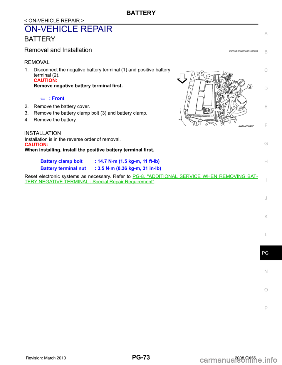
1. Disconnect the negative battery terminal (1) and positive battery
terminal (2).
CAUTION:
Remove negative battery terminal first.
2. Remove the battery cover.
3. Remove the battery clamp bolt (3) and battery clamp.
4. Remove the battery.
INSTALLATION
Installation is in the reverse order of removal.
CAUTION:
When installing, in stall the positive battery terminal first.
Reset electronic systems as necessary. Refer to PG-8, "
ADDITIONAL SERVICE WHEN REMOVING BAT-
TERY NEGATIVE TERMINAL : Special Repair Requirement".
⇐
: Front
AWBIA0504ZZ
Battery clamp bolt : 14.7 N·m (1.5 kg-m, 11 ft-lb)
Battery terminal nut : 3.5 N·m (0.36 kg-m, 31 in-lb)
Revision: March 2010 2008 QX56
Page 2989 of 4083

INSPECTION AND ADJUSTMENTRF-5
< BASIC INSPECTION >
C
DE
F
G H
I
J
L
M A
B
RF
N
O P
INSPECTION AND ADJUSTMENT
ADDITIONAL SERVICE WHEN REPLACING CONTROL UNIT
ADDITIONAL SERVICE WHEN REPL ACING CONTROL UNIT : Description
INFOID:0000000001731919
MEMORY RESET PROCEDURE
1. Please observe the following instructi ons at confirming the sunroof operation.
NOTE:
Do not disconnect the electronic power while the sunroof is operating or within 5 seconds after the sunroof
stops. (to wipe-out the memory of lid position and operating friction.)
2. Initialization of system should be conducted after the following conditions.
• When the sunroof motor is changed.
• When the sunroof does not operate normally. (Incomplete initialization conditions)
ADDITIONAL SERVICE WHEN REPLACING CONTROL UNIT : Special Repair Re-
quirement
INFOID:0000000001731920
INITIALIZATION PROCEDURE
If the sunroof does not close or open automatically, us e the following procedure to return sunroof operation to
normal.
1. Turn ignition switch ON.
2. Push and hold the sunroof tilt switch in the forw ard (DOWN) position until the sunroof is fully closed.
3. After the sunroof has closed all the way, push and hold the tilt switch forward (DOWN) again for more than 2 seconds to re-learn motor position.
4. Initialization is complete if the sunroof operates normally.
BASIC INSPECTION
BASIC INSPECTION : Special Repair RequirementINFOID:0000000001731921
BASIC INSPECTION
1.INSPECTION START
1. Check the service history.
2. Check the following parts.
• Fuse/circuit breaker blown.
• Poor connection, open or short circuit of harness connector.
• Battery voltage.
Is the inspection result normal?
YES >> Inspection End.
NO >> Repair or replace the malfunctioning parts.
Revision: March 2010 2008 QX56
Page 3039 of 4083

SUNROOF SYSTEMRF-55
< ON-VEHICLE REPAIR >
C
DE
F
G H
I
J
L
M A
B
RF
N
O P
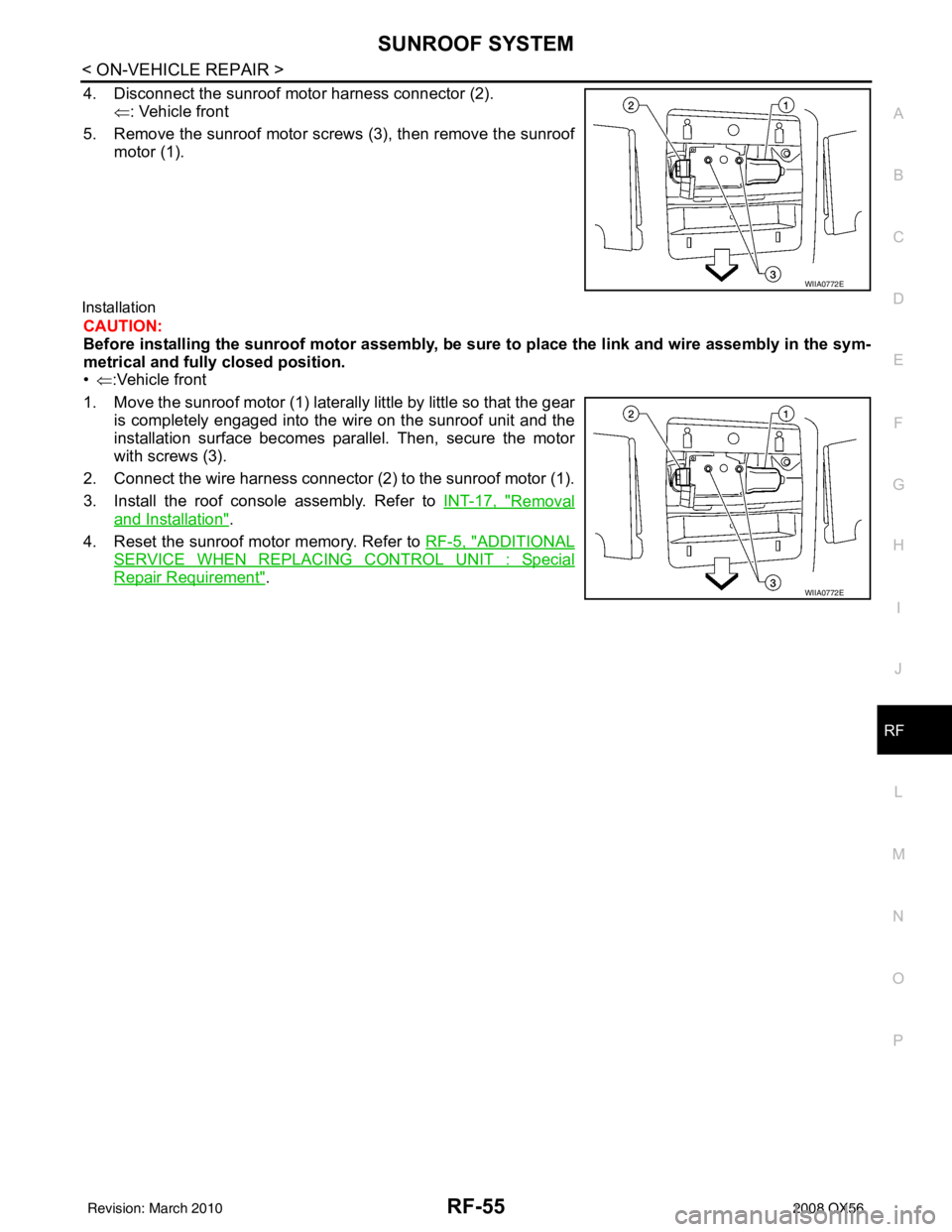
4. Disconnect the sunroof motor harness connector (2). ⇐: Vehicle front
5. Remove the sunroof motor screws (3), then remove the sunroof motor (1).
Installation
CAUTION:
Before installing the sunroof motor assembly, be sure to place the link and wire assembly in the sym-
metrical and fully closed position.
•⇐ :Vehicle front
1. Move the sunroof motor (1) laterally little by little so that the gear is completely engaged into the wire on the sunroof unit and the
installation surface becomes parallel. Then, secure the motor
with screws (3).
2. Connect the wire harness connector (2) to the sunroof motor (1).
3. Install the roof console assembly. Refer to INT-17, "
Removal
and Installation".
4. Reset the sunroof motor memory. Refer to RF-5, "
ADDITIONAL
SERVICE WHEN REPLACING CONTROL UNIT : Special
Repair Requirement".
WIIA0772E
WIIA0772E
Revision: March 2010 2008 QX56