2008 INFINITI FX35 key battery
[x] Cancel search: key batteryPage 2644 of 3924
![INFINITI FX35 2008 Service Manual
EM-160
< SERVICE INFORMATION >[VK45DE]
PRECAUTIONS
SERVICE INFORMATION
PRECAUTIONS
Precaution Necessary for Steering W
heel Rotation After Battery Disconnect
INFOID:0000000001524895
NOTE:
This Proc INFINITI FX35 2008 Service Manual
EM-160
< SERVICE INFORMATION >[VK45DE]
PRECAUTIONS
SERVICE INFORMATION
PRECAUTIONS
Precaution Necessary for Steering W
heel Rotation After Battery Disconnect
INFOID:0000000001524895
NOTE:
This Proc](/manual-img/42/57017/w960_57017-2643.png)
EM-160
< SERVICE INFORMATION >[VK45DE]
PRECAUTIONS
SERVICE INFORMATION
PRECAUTIONS
Precaution Necessary for Steering W
heel Rotation After Battery Disconnect
INFOID:0000000001524895
NOTE:
This Procedure is applied only to models with In telligent Key system and NVIS/IVIS (NISSAN/INFINITI
VEHICLE IMMOBILIZER SYSTEM - NATS).
Remove and install all control units after disconnecting both battery cables with the ignition knob in the ″LOCK ″ position.
Always use CONSULT-III to perform self-diagnosis as a part of each function inspection after finishing work.
If DTC is detected, perform trouble diagnosis according to self-diagnostic results.
For models equipped with the Intelligent Key system and NVIS /IVIS, an electrically controlled steering lock
mechanism is adopted on the key cylinder.
For this reason, if the battery is disconnected or if the battery is discharged, the steering wheel will lock and
steering wheel rotation will become impossible.
If steering wheel rotation is required when battery pow er is interrupted, follow the procedure below before
starting the repair operation.
OPERATION PROCEDURE
1. Connect both battery cables. NOTE:
Supply power using jumper cables if battery is discharged.
2. Use the Intelligent Key or mechanical key to turn the ignition switch to the ″ACC ″ position. At this time, the
steering lock will be released.
3. Disconnect both battery cables. The steering lock will remain released and the steering wheel can be
rotated.
4. Perform the necessary repair operation.
5. When the repair work is completed, return the ignition switch to the ″LOCK ″ position before connecting
the battery cables. (At this time, the steering lock mechanism will engage.)
6. Perform a self-diagnosis check of all control units using CONSULT-III.
Precaution for Drain Engine Coolant and Engine OilINFOID:0000000001325752
Drain engine coolant and engine oil when engine is cooled.
Precaution for Disconnecting Fuel PipingINFOID:0000000001325753
Before starting work, make sure no fire or spark producing items are in the work area.
Release fuel pressure before disconnecting and disassembly.
After disconnecting pipes, plug openings to stop fuel leakage.
Precaution for Removal and DisassemblyINFOID:0000000001325754
When instructed to use SST, use specified tools. Always be careful to work safely, avoid forceful or unin-
structed operations.
Exercise maximum care to avoid damage to mating or sliding surfaces.
Cover openings of engine system with tape or the equival ent, if necessary, to seal out foreign materials.
Mark and arrange disassembly parts in an organi zed way for easy troubleshooting and assembly.
When loosening nuts and bolts, as a basic rule, star t with the one furthest outside, then the one diagonally
opposite, and so on. If the order of loosening is specified, do exactly as specified. Power tools may be used
where noted in the step.
Precaution for Inspection, Repair and ReplacementINFOID:0000000001325755
Before repairing or replacing, thoroughly inspect parts. Inspect new replacement parts in the same way, and
replace if necessary.
3AA93ABC3ACD3AC03ACA3AC03AC63AC53A913A773A893A873A873A8E3A773A983AC73AC93AC03AC3
3A893A873A873A8F3A773A9D3AAF3A8A3A8C3A863A9D3AAF3A8B3A8C
Page 2864 of 3924
GI-2
< SERVICE INFORMATION >
PRECAUTIONS
SERVICE INFORMATION
PRECAUTIONS
DescriptionINFOID:0000000001325649
Observe the following precautions to ensure safe and proper servicing. These precautions are not
described in each individual section.
Precaution for Supplemental Restraint S ystem (SRS) "AIR BAG" and "SEAT BELT
PRE-TENSIONER"
INFOID:0000000001612904
The Supplemental Restraint System such as “A IR BAG” and “SEAT BELT PRE-TENSIONER”, used along
with a front seat belt, helps to reduce the risk or severi ty of injury to the driver and front passenger for certain
types of collision. This system includes seat belt switch inputs and dual stage front air bag modules. The SRS
system uses the seat belt switches to determine the front air bag deployment, and may only deploy one front
air bag, depending on the severity of a collision and w hether the front occupants are belted or unbelted.
Information necessary to service the system safely is included in the “SUPPLEMENTAL RESTRAINT SYS-
TEM” and “SEAT BELTS” of this Service Manual.
WARNING:
• To avoid rendering the SRS inopera tive, which could increase the risk of personal injury or death in
the event of a collision which would result in air bag inflation, all maintenance must be performed by
an authorized NISS AN/INFINITI dealer.
Improper maintenance, including in correct removal and installation of the SRS, can lead to personal
injury caused by unintent ional activation of the system. For re moval of Spiral Cable and Air Bag
Module, see the “SUPPLEMEN TAL RESTRAINT SYSTEM”.
Do not use electrical test equipmen t on any circuit related to the SRS unless instructed to in this
Service Manual. SRS wiring harnesses can be identi fied by yellow and/or orange harnesses or har-
ness connectors.
Precaution Necessary for Steering W heel Rotation After Battery Disconnect
INFOID:0000000001612934
NOTE:
This Procedure is applied only to models with In telligent Key system and NVIS/IVIS (NISSAN/INFINITI
VEHICLE IMMOBILIZER SYSTEM - NATS).
Remove and install all control units after disconnecting both battery cables with the ignition knob in the ″LOCK ″ position.
Always use CONSULT-III to perform self-diagnosis as a part of each function inspection after finishing work.
If DTC is detected, perform trouble diagnosis according to self-diagnostic results.
For models equipped with the Intelligent Key system and NVIS /IVIS, an electrically controlled steering lock
mechanism is adopted on the key cylinder.
For this reason, if the battery is disconnected or if the battery is discharged, the steering wheel will lock and
steering wheel rotation will become impossible.
If steering wheel rotation is required when battery pow er is interrupted, follow the procedure below before
starting the repair operation.
OPERATION PROCEDURE
1. Connect both battery cables. NOTE:
Supply power using jumper cables if battery is discharged.
2. Use the Intelligent Key or mechanical key to turn the ignition switch to the ″ACC ″ position. At this time, the
steering lock will be released.
3. Disconnect both battery cables. The steering lock will remain released and the steering wheel can be
rotated.
4. Perform the necessary repair operation.
5. When the repair work is completed, return the ignition switch to the ″LOCK ″ position before connecting
the battery cables. (At this time, the steering lock mechanism will engage.)
6. Perform a self-diagnosis check of all control units using CONSULT-III.
3AA93ABC3ACD3AC03ACA3AC03AC63AC53A913A773A893A873A873A8E3A773A983AC73AC93AC03AC3
3A893A873A873A8F3A773A9D3AAF3A8A3A8C3A863A9D3AAF3A8B3A8C
Page 2872 of 3924
GI-10
< SERVICE INFORMATION >
HOW TO USE THIS MANUAL
3.Refer to Component Parts and Harness Connector Location for the Systems described in each
section for identifi cation/location of componen ts and harness connectors.
4. Refer to the Circuit Diagra m for quick pinpoint check.
If you need to check circuit continuity between harness connectors in more detail, such as when a
sub-harness is used, refer to Wiring Diagram in each individual section and Harness Layout in PG
section for identificatio n of harness connectors.
5. When checking circuit continuity, ignition switch should be OFF.
6. Before checking voltage at co nnectors, check battery voltage.
7. After accomplishing the Diagnost ic Procedures and Electrical Components Inspection, make sure
that all harness connectors ar e reconnected as they were.
HOW TO FOLLOW TEST GROUPS IN TROUBLE DIAGNOSES
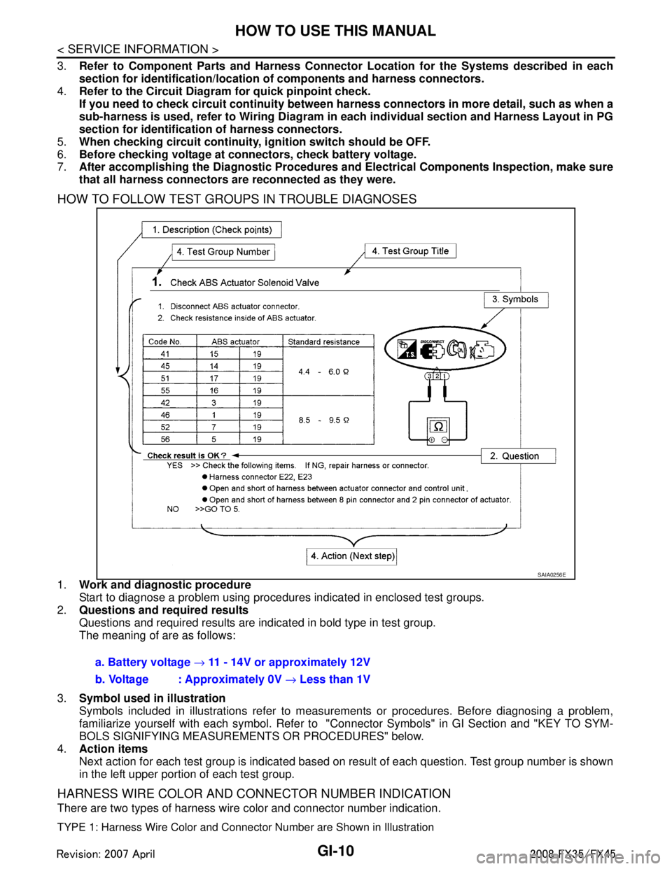
1.Work and diagnostic procedure
Start to diagnose a problem using procedures indicated in enclosed test groups.
2. Questions and required results
Questions and required results are indicated in bold type in test group.
The meaning of are as follows:
3. Symbol used in illustration
Symbols included in illustrations refer to measur ements or procedures. Before diagnosing a problem,
familiarize yourself with each symbol. Refer to "Connector Symbols" in GI Section and "KEY TO SYM-
BOLS SIGNIFYING MEASUREME NTS OR PROCEDURES" below.
4. Action items
Next action for each test group is indicated based on result of each question. Test group number is shown
in the left upper portion of each test group.
HARNESS WIRE COLOR AND CONNECTOR NUMBER INDICATION
There are two types of harness wire color and connector number indication.
TYPE 1: Harness Wire Color and Connec tor Number are Shown in Illustration
SAIA0256E
a. Battery voltage → 11 - 14V or approximately 12V
b. Voltage : Approximately 0V → Less than 1V
3AA93ABC3ACD3AC03ACA3AC03AC63AC53A913A773A893A873A873A8E3A773A983AC73AC93AC03AC3
3A893A873A873A8F3A773A9D3AAF3A8A3A8C3A863A9D3AAF3A8B3A8C
Page 2891 of 3924
SERVICE INFORMATION FOR ELECTRICAL INCIDENTGI-29
< SERVICE INFORMATION >
C
DE
F
G H
I
J
K L
M B
GI
N
O P
Close the relay and probe at the solenoid. voltage; open is further down the circuit than the solenoid.
no voltage; open is between relay and solenoid (point C).
Any powered circuit can be diagnosed using the approach in the previous example.
Testing for “Shorts” in the Circuit
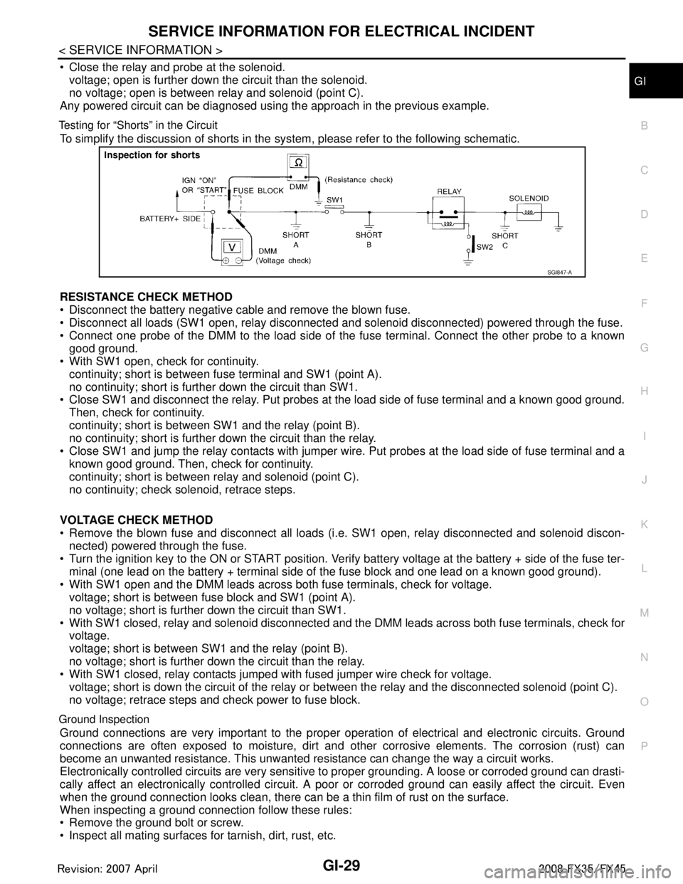
To simplify the discussion of shorts in the system, please refer to the following schematic.
RESISTANCE CHECK METHOD
Disconnect the battery negative cable and remove the blown fuse.
Disconnect all loads (SW1 open, relay disconnected and solenoid disconnected) powered through the fuse.
Connect one probe of the DMM to the load side of the fuse terminal. Connect the other probe to a known
good ground.
With SW1 open, check for continuity.
continuity; short is between fuse terminal and SW1 (point A).
no continuity; short is further down the circuit than SW1.
Close SW1 and disconnect the relay. Put probes at the load side of fuse terminal and a known good ground.
Then, check for continuity.
continuity; short is between SW1 and the relay (point B).
no continuity; short is further down the circuit than the relay.
Close SW1 and jump the relay contacts with jumper wir e. Put probes at the load side of fuse terminal and a
known good ground. Then, check for continuity.
continuity; short is between relay and solenoid (point C).
no continuity; check solenoid, retrace steps.
VOLTAGE CHECK METHOD
Remove the blown fuse and disconnect all loads (i .e. SW1 open, relay disconnected and solenoid discon-
nected) powered through the fuse.
Turn the ignition key to the ON or START position. Veri fy battery voltage at the battery + side of the fuse ter-
minal (one lead on the battery + terminal side of the fuse block and one lead on a known good ground).
With SW1 open and the DMM leads across both fuse terminals, check for voltage.
voltage; short is between fuse block and SW1 (point A).
no voltage; short is further down the circuit than SW1.
With SW1 closed, relay and solenoid disconnected and t he DMM leads across both fuse terminals, check for
voltage.
voltage; short is between SW1 and the relay (point B).
no voltage; short is further down the circuit than the relay.
With SW1 closed, relay contacts jumped with fused jumper wire check for voltage.
voltage; short is down the circuit of the relay or between the relay and the disconnected solenoid (point C).
no voltage; retrace steps and check power to fuse block.
Ground Inspection
Ground connections are very important to the proper oper ation of electrical and electronic circuits. Ground
connections are often exposed to moisture, dirt and other corrosive elements. The corrosion (rust) can
become an unwanted resistance. This unwanted re sistance can change the way a circuit works.
Electronically controlled circuits are very sensitive to proper grounding. A loose or corroded ground can drasti-
cally affect an electronically controlled circuit. A poor or corroded ground can easily affect the circuit. Even
when the ground connection looks clean, there can be a thin film of rust on the surface.
When inspecting a ground connection follow these rules:
Remove the ground bolt or screw.
Inspect all mating surfaces for tarnish, dirt, rust, etc.
SGI847-A
3AA93ABC3ACD3AC03ACA3AC03AC63AC53A913A773A893A873A873A8E3A773A983AC73AC93AC03AC3
3A893A873A873A8F3A773A9D3AAF3A8A3A8C3A863A9D3AAF3A8B3A8C
Page 2902 of 3924
GI-40
< SERVICE INFORMATION >
TOW TRUCK TOWING
TOW TRUCK TOWING
Tow Truck TowingINFOID:0000000001325684
CAUTION:
All applicable state or Provincial (in Canada) laws and local laws regarding the towing operation
must be obeyed.
It is necessary to use proper towi ng equipment to avoid possible damage to the vehicle during tow-
ing operation. To wing is in accordance with Towing Procedure Manual at dealer.
Always attach safety chains before towing.
When towing, make sure that the transmission, steering system and powertrain are in good order. If
any unit is damaged, dollies must be used.
Never tow an automatic transmission model from the rear (that is backward) with four wheels on the
ground. This may cause serious and exp ensive damage to the transmission.
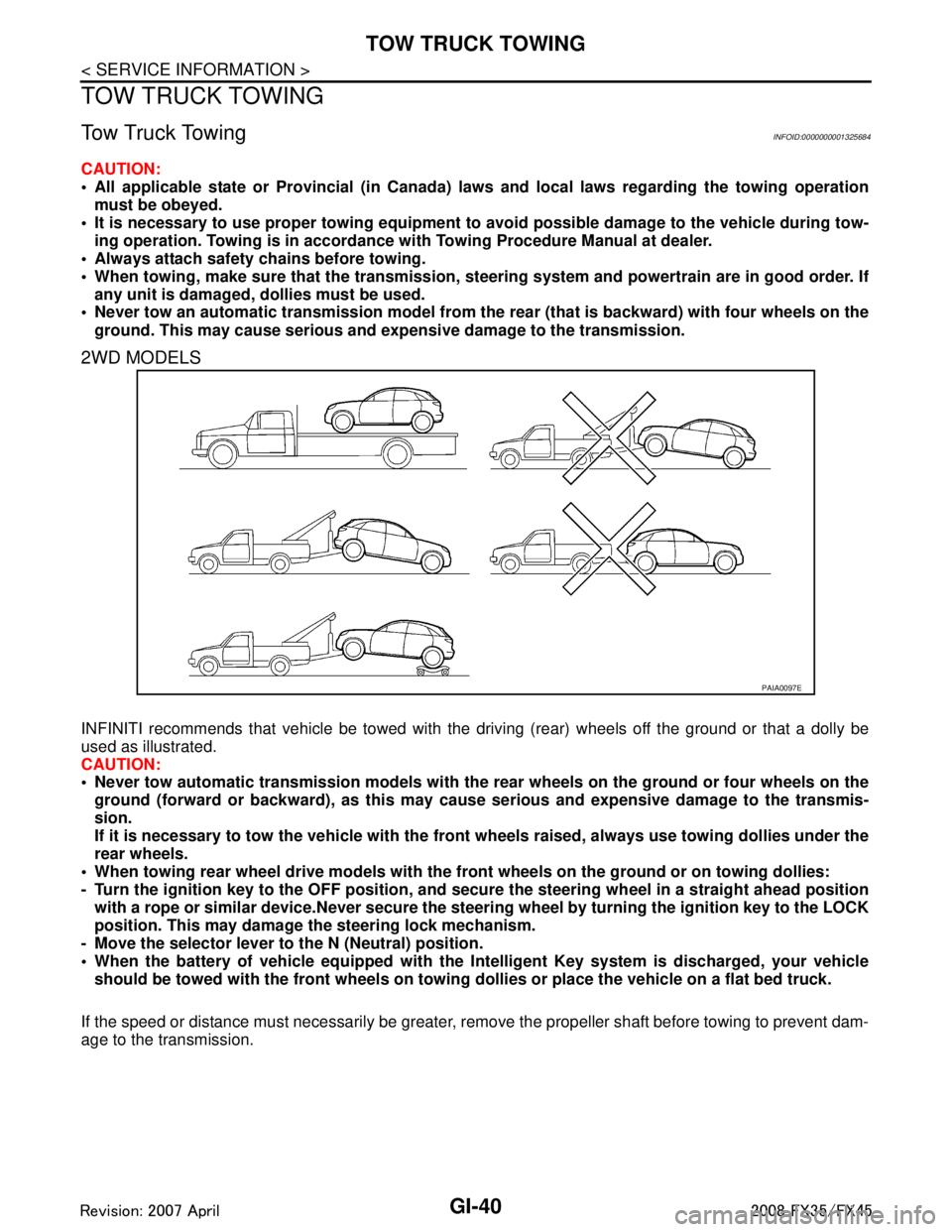
2WD MODELS
INFINITI recommends that vehicle be towed with the dr iving (rear) wheels off the ground or that a dolly be
used as illustrated.
CAUTION:
Never tow automatic transmission models with the r ear wheels on the ground or four wheels on the
ground (forward or backward), as this may cause serious and expensive damage to the transmis-
sion.
If it is necessary to tow the vehicle with the fron t wheels raised, always use towing dollies under the
rear wheels.
When towing rear wheel drive mo dels with the front wheels on the ground or on towing dollies:
- Turn the ignition key to the OFF position, and secure the steering wh eel in a straight ahead position
with a rope or similar device.Never secure the st eering wheel by turning the ignition key to the LOCK
position. This may damage the steering lock mechanism.
- Move the selector lever to the N (Neutral) position.
When the battery of vehicle equipped with the Intelligent Key system is discharged, your vehicle
should be towed with the front wh eels on towing dollies or place the vehicle on a flat bed truck.
If the speed or distance must necessarily be greater, re move the propeller shaft before towing to prevent dam-
age to the transmission.
PAIA0097E
3AA93ABC3ACD3AC03ACA3AC03AC63AC53A913A773A893A873A873A8E3A773A983AC73AC93AC03AC3
3A893A873A873A8F3A773A9D3AAF3A8A3A8C3A863A9D3AAF3A8B3A8C
Page 2937 of 3924
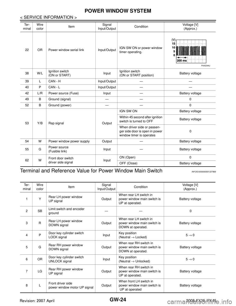
GW-24
< SERVICE INFORMATION >
POWER WINDOW SYSTEM
Terminal and Reference Value for Power Window Main Switch
INFOID:0000000001327969
22 OR Power window serial link Input/Output IGN SW ON or power window
timer operating.
38 W/L Ignition switch
(ON or START) InputIgnition switch
(ON or START position) Battery voltage
39 L CAN - H Input/Output — —
40 P CAN - L Input/Output — —
42 L/R Power source (Fuse) Input — Battery voltage
49 B Ground (signal) — — 0
52 B Ground (power) — — 0
53 Y/B Rap signal Output IGN SW ON Battery voltage
Within 45 second after ignition
switch is turned to OFF
Battery voltage
When driver side or passen-
ger side door is open in power
window timer is operates 0
54 W Power window power supply Output — Battery voltage
55 G Power source
(Fusible link)
Input — Battery voltage
62 W Front door switch
driver side signal InputON (Open) 0
OFF (Close) Battery voltage
Te r -
minal Wire
color Item Signal
Input/Output Condition Voltage [V]
(Approx.)
PIIA2344J
Te r -
minal Wire
color Item Signal
Input/Output Condition Voltage [V]
(Approx.)
1Y Rear LH power window
UP signal OutputWhen rear LH switch in
power window main switch is
UP at operated. Battery voltage
2SB Limit switch and encoder
ground —— 0
3R Rear LH power window
DOWN signal OutputWhen rear LH switch in
power window main switch is
DOWN at operated. Battery voltage
4P Door key cylinder switch
LOCK signal InputKey position
(Neutral
→ Locked) 5
→ 0
5G Rear RH power window
DOWN signal OutputWhen rear RH switch in
power window main switch is
DOWN at operated. Battery voltage
6OR Door key cylinder switch
UNLOCK signal Input
Key position
(Neutral
→ Unlocked) 5
→ 0
7LG Rear RH power window
UP signal OutputWhen rear RH switch in
power window main switch is
UP at operated. Battery voltage
8L Front driver side
power window motor UP signal
OutputWhen front LH switch in
power window main switch is
UP at operated
Battery voltage
3AA93ABC3ACD3AC03ACA3AC03AC63AC53A913A773A893A873A873A8E3A773A983AC73AC93AC03AC3
3A893A873A873A8F3A773A9D3AAF3A8A3A8C3A863A9D3AAF3A8B3A8C
Page 2956 of 3924
POWER WINDOW SYSTEMGW-43
< SERVICE INFORMATION >
C
DE
F
G H
J
K L
M A
B
GW
N
O P
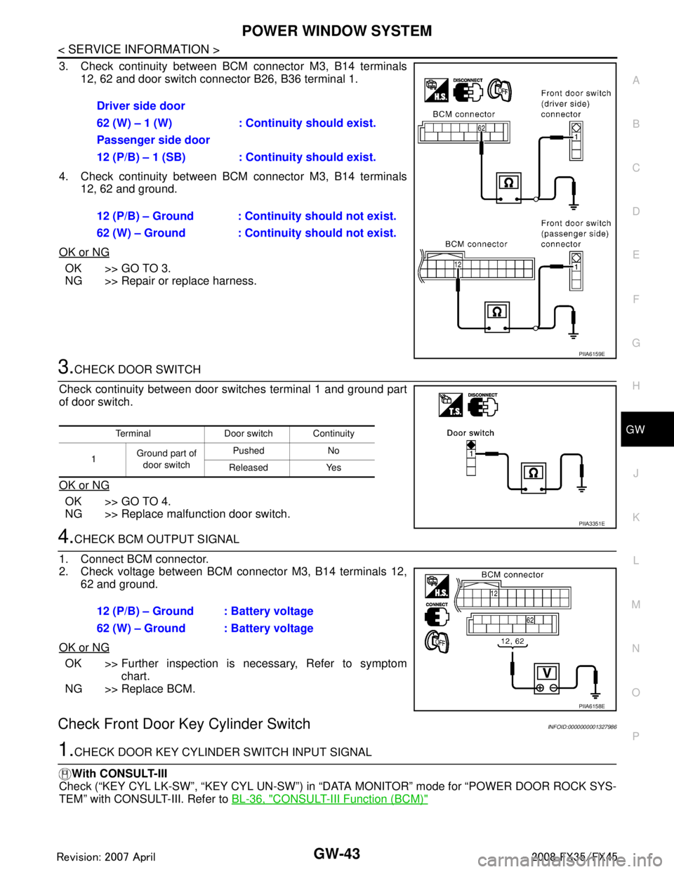
3. Check continuity between BCM connector M3, B14 terminals 12, 62 and door switch connector B26, B36 terminal 1.
4. Check continuity between BCM connector M3, B14 terminals 12, 62 and ground.
OK or NG
OK >> GO TO 3.
NG >> Repair or replace harness.
3.CHECK DOOR SWITCH
Check continuity between door switches terminal 1 and ground part
of door switch.
OK or NG
OK >> GO TO 4.
NG >> Replace malfunction door switch.
4.CHECK BCM OUTPUT SIGNAL
1. Connect BCM connector.
2. Check voltage between BCM connector M3, B14 terminals 12, 62 and ground.
OK or NG
OK >> Further inspection is necessary, Refer to symptom chart.
NG >> Replace BCM.
Check Front Door Key Cylinder SwitchINFOID:0000000001327986
1.CHECK DOOR KEY CYLINDER SWITCH INPUT SIGNAL
With CONSULT-III
Check (“KEY CYL LK-SW”, “KEY CYL UN-SW”) in “D ATA MONITOR” mode for “POWER DOOR ROCK SYS-
TEM” with CONSULT-III. Refer to BL-36, "
CONSULT-III Function (BCM)"
Driver side door
62 (W) – 1 (W) : Continuity should exist.
Passenger side door
12 (P/B) – 1 (SB) : Continuity should exist.
12 (P/B) – Ground : Contin uity should not exist.
62 (W) – Ground : Contin uity should not exist.
PIIA6159E
Terminal Door switch Continuity
1 Ground part of
door switch Pushed No
Released Yes
PIIA3351E
12 (P/B) – Ground : Battery voltage
62 (W) – Ground : Battery voltage
PIIA6158E
3AA93ABC3ACD3AC03ACA3AC03AC63AC53A913A773A893A873A873A8E3A773A983AC73AC93AC03AC3
3A893A873A873A8F3A773A9D3AAF3A8A3A8C3A863A9D3AAF3A8B3A8C
Page 3064 of 3924
![INFINITI FX35 2008 Service Manual
LAN-44
< SERVICE INFORMATION >[CAN]
TROUBLE DIAGNOSIS
Check CAN system type from the vehicle shape and equipment.
CAN Communication Signal ChartINFOID:0000000001328636
Refer to
LAN-13, "How to Use C INFINITI FX35 2008 Service Manual
LAN-44
< SERVICE INFORMATION >[CAN]
TROUBLE DIAGNOSIS
Check CAN system type from the vehicle shape and equipment.
CAN Communication Signal ChartINFOID:0000000001328636
Refer to
LAN-13, "How to Use C](/manual-img/42/57017/w960_57017-3063.png)
LAN-44
< SERVICE INFORMATION >[CAN]
TROUBLE DIAGNOSIS
Check CAN system type from the vehicle shape and equipment.
CAN Communication Signal ChartINFOID:0000000001328636
Refer to
LAN-13, "How to Use CAN Communication Signal Chart" for how to use CAN communication signal
chart.
TYPE 1/TYPE 2
NOTE:
Refer to LAN-37, "
Abbreviation List" for the abbreviations of the connecting units.
T: Transmit R: Receive
PKID0615E
Signal name/Connecting unitECM
DISP TCM
BCM
I-KEY
STRG M&AABS
ADP
IPDM-E
A/C compressor feedback signal T R
A/C compressor request signal T R
Accelerator pedal position signal T R R
ASCD CRUISE lamp signal T R
ASCD OD cancel request signal T R
ASCD operation signal T R
ASCD SET lamp signal T R
Battery voltage signal T R
Closed throttle position signal T R
Cooling fan speed request signal T R
Engine coolant temperature signal T R
Engine speed signal T R R R R
Engine status signal T R
Fuel consumption monitor signal TR
RT
Malfunctioning indicator lamp signal T R
Wide open throttle position signal T R
A/C switch/indicator signal TR
RT
System setting signal TR R
RT T
A/T CHECK indicator lamp signal T R
A/T self-diagnosis signal R T
3AA93ABC3ACD3AC03ACA3AC03AC63AC53A913A773A893A873A873A8E3A773A983AC73AC93AC03AC3
3A893A873A873A8F3A773A9D3AAF3A8A3A8C3A863A9D3AAF3A8B3A8C