Page 3715 of 3924

SE-76
< SERVICE INFORMATION >
AUTOMATIC DRIVE POSITIONER
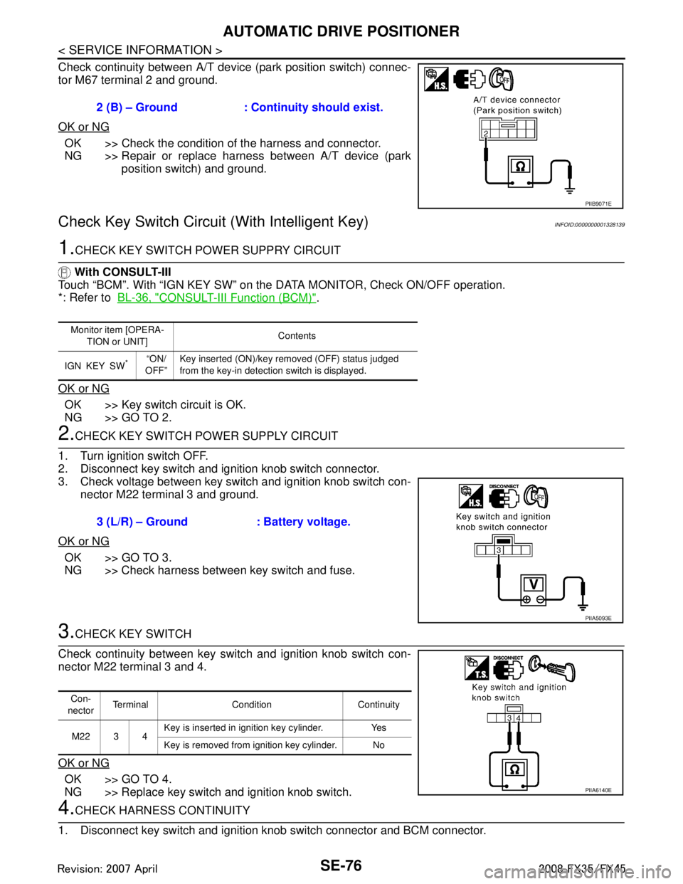
Check continuity between A/T device (park position switch) connec-
tor M67 terminal 2 and ground.
OK or NG
OK >> Check the condition of the harness and connector.
NG >> Repair or replace harness between A/T device (park position switch) and ground.
Check Key Switch Circuit (With Intelligent Key)INFOID:0000000001328139
1.CHECK KEY SWITCH POWER SUPPRY CIRCUIT
With CONSULT-III
Touch “BCM”. With “IGN KEY SW” on the DATA MONITOR, Check ON/OFF operation.
*: Refer to BL-36, "
CONSULT-III Function (BCM)".
OK or NG
OK >> Key switch circuit is OK.
NG >> GO TO 2.
2.CHECK KEY SWITCH PO WER SUPPLY CIRCUIT
1. Turn ignition switch OFF.
2. Disconnect key switch and ignition knob switch connector.
3. Check voltage between key switch and ignition knob switch con- nector M22 terminal 3 and ground.
OK or NG
OK >> GO TO 3.
NG >> Check harness between key switch and fuse.
3.CHECK KEY SWITCH
Check continuity between key switch and ignition knob switch con-
nector M22 terminal 3 and 4.
OK or NG
OK >> GO TO 4.
NG >> Replace key switch and ignition knob switch.
4.CHECK HARNESS CONTINUITY
1. Disconnect key switch and ignition knob switch connector and BCM connector. 2 (B) – Ground : Continuity should exist.
PIIB9071E
Monitor item [OPERA-
TION or UNIT] Contents
IGN KEY SW
*“ON/
OFF” Key inserted (ON)/key removed (OFF) status judged
from the key-in detection switch is displayed.
3 (L/R) – Ground : Battery voltage.
PIIA5093E
Con-
nector Terminal Condition Continuity
M22 3 4 Key is inserted in ignition key cylinder. Yes
Key is removed from ignition key cylinder. No
PIIA6140E
3AA93ABC3ACD3AC03ACA3AC03AC63AC53A913A773A893A873A873A8E3A773A983AC73AC93AC03AC3
3A893A873A873A8F3A773A9D3AAF3A8A3A8C3A863A9D3AAF3A8B3A8C
Page 3716 of 3924

AUTOMATIC DRIVE POSITIONERSE-77
< SERVICE INFORMATION >
C
DE
F
G H
J
K L
M A
B
SE
N
O P
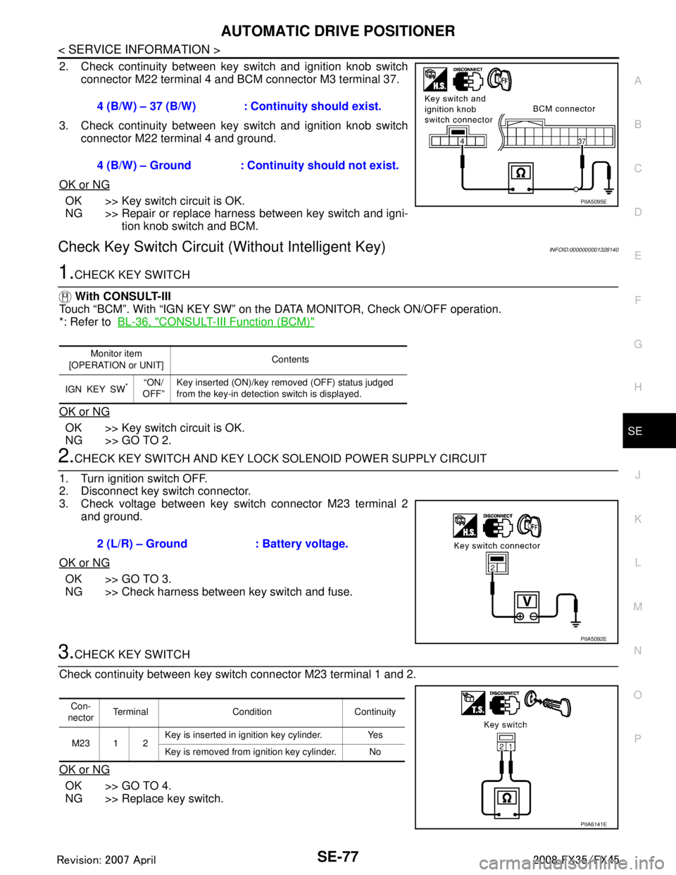
2. Check continuity between key switch and ignition knob switch connector M22 terminal 4 and BCM connector M3 terminal 37.
3. Check continuity between key switch and ignition knob switch connector M22 terminal 4 and ground.
OK or NG
OK >> Key switch circuit is OK.
NG >> Repair or replace harness between key switch and igni- tion knob switch and BCM.
Check Key Switch Circui t (Without Intelligent Key)INFOID:0000000001328140
1.CHECK KEY SWITCH
With CONSULT-III
Touch “BCM”. With “IGN KEY SW” on the DATA MONITOR, Check ON/OFF operation.
*: Refer to BL-36, "
CONSULT-III Function (BCM)"
OK or NG
OK >> Key switch circuit is OK.
NG >> GO TO 2.
2.CHECK KEY SWITCH AND KEY LOCK SOLENOID POWER SUPPLY CIRCUIT
1. Turn ignition switch OFF.
2. Disconnect key switch connector.
3. Check voltage between key switch connector M23 terminal 2 and ground.
OK or NG
OK >> GO TO 3.
NG >> Check harness between key switch and fuse.
3.CHECK KEY SWITCH
Check continuity between key switch connector M23 terminal 1 and 2.
OK or NG
OK >> GO TO 4.
NG >> Replace key switch. 4 (B/W) – 37 (B/W) : Cont
inuity should exist.
4 (B/W) – Ground : Continuity should not exist.
PIIA5095E
Monitor item
[OPERATION or UNIT] Contents
IGN KEY SW
*“ON/
OFF” Key inserted (ON)/key removed (OFF) status judged
from the key-in detection switch is displayed.
2 (L/R) – Ground : Battery voltage.
PIIA5092E
Con-
nector Terminal Condition Continuity
M23 1 2 Key is inserted in ignition key cylinder. Yes
Key is removed from ignition key cylinder. No
PIIA6141E
3AA93ABC3ACD3AC03ACA3AC03AC63AC53A913A773A893A873A873A8E3A773A983AC73AC93AC03AC3
3A893A873A873A8F3A773A9D3AAF3A8A3A8C3A863A9D3AAF3A8B3A8C
Page 3858 of 3924
WT-18
< SERVICE INFORMATION >
TROUBLE DIAGNOSES
Te r m i n a lItem Condition Voltage (V)
Approx. value
+ (wire color) –
15 (G)
Ground Tire pressure
warning check
connector Always 5V
18 (B) Remote keyless entry receiver
(Ground) —0V
19 (R) Remote keyless entry receiver
(Power supply) Stand-by
Press any of the keyfob switch-
es
20 (Y) Remote keyless entry receiver
(Signal) Stand-by
Press any of the keyfob switch-
es
38 (W/L) Ignition switch Ignition switch ON or START Battery voltage (12V) 39 (L) CAN-H — —
40 (P) CAN-L — —
42 (L/R) Battery power supply (Fuse) Always Battery voltage (12V)
45 (G/W) Turn signal (left) Ignition switch ON
Combination switch is turn
signal (left)
OCC3879D
OCC3882D
OCC3881D
OCC3880D
SKIA3009J
3AA93ABC3ACD3AC03ACA3AC03AC63AC53A913A773A893A873A873A8E3A773A983AC73AC93AC03AC3
3A893A873A873A8F3A773A9D3AAF3A8A3A8C3A863A9D3AAF3A8B3A8C