2008 INFINITI FX35 key battery
[x] Cancel search: key batteryPage 1184 of 3924

DI-58
< SERVICE INFORMATION >
WARNING CHIME
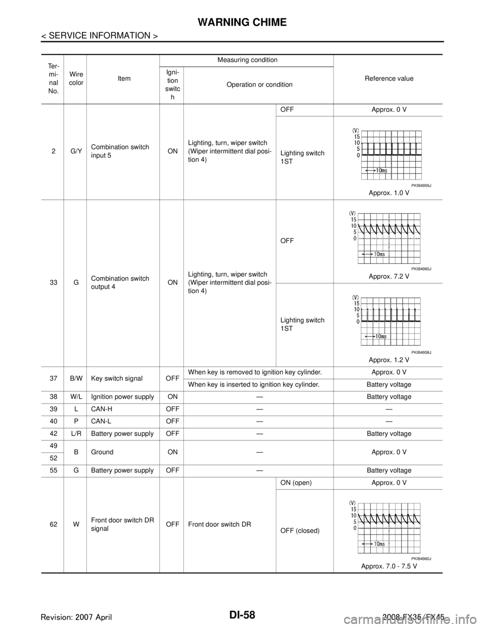
Te r -mi-
nal
No. Wire
color Item Measuring condition
Reference value
Igni-
tion
switc h Operation or condition
2G/Y Combination switch
input 5 ONLighting, turn, wiper switch
(Wiper intermittent dial posi-
tion 4) OFF Approx. 0 V
Lighting switch
1ST
Approx. 1.0 V
33 G Combination switch
output 4 ONLighting, turn, wiper switch
(Wiper intermittent dial posi-
tion 4) OFF
Approx. 7.2 V
Lighting switch
1ST Approx. 1.2 V
37 B/W Key switch signal OFF When key is removed to ignition key cylinder. Approx. 0 V
When key is inserted to ignition key cylinder. Battery voltage
38 W/L Ignition power supply ON — Battery voltage
39 L CAN-H OFF — —
40 P CAN-L OFF — —
42 L/R Battery power supply OFF — Battery voltage
49 B Ground ON — Approx. 0 V
52
55 G Battery power supp ly OFF — Battery voltage
62 W Front door switch DR
signal
OFF Front door switch DR ON (open) Approx. 0 V
OFF (closed)
Approx. 7.0 - 7.5 V
PKIB4959J
PKIB4960J
PKIB4958J
PKIB4960J
3AA93ABC3ACD3AC03ACA3AC03AC63AC53A913A773A893A873A873A8E3A773A983AC73AC93AC03AC3
3A893A873A873A8F3A773A9D3AAF3A8A3A8C3A863A9D3AAF3A8B3A8C
Page 1188 of 3924

DI-62
< SERVICE INFORMATION >
WARNING CHIME
OK or NG
OK >> GO TO 2.
NG >> Be sure to eliminate cause of malfunction before installing new fuse or fusible link. Refer to PG-3
.
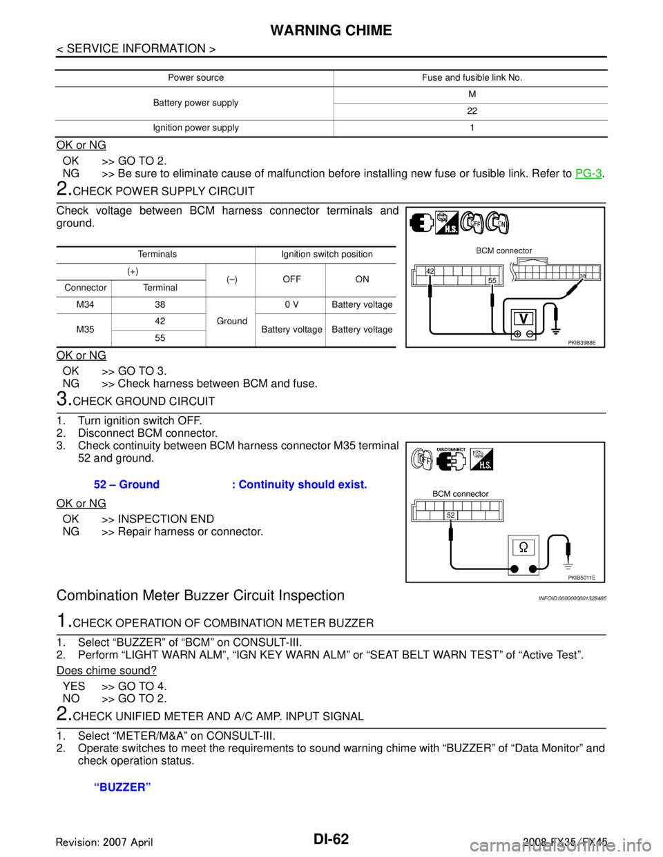
2.CHECK POWER SUPPLY CIRCUIT
Check voltage between BCM harness connector terminals and
ground.
OK or NG
OK >> GO TO 3.
NG >> Check harness between BCM and fuse.
3.CHECK GROUND CIRCUIT
1. Turn ignition switch OFF.
2. Disconnect BCM connector.
3. Check continuity between BCM harness connector M35 terminal 52 and ground.
OK or NG
OK >> INSPECTION END
NG >> Repair harness or connector.
Combination Meter Buzzer Circuit InspectionINFOID:0000000001328485
1.CHECK OPERATION OF COMBINATION METER BUZZER
1. Select “BUZZER” of “BCM” on CONSULT-III.
2. Perform “LIGHT WARN ALM”, “IGN KEY WARN AL M” or “SEAT BELT WARN TEST” of “Active Test”.
Does chime sound?
YES >> GO TO 4.
NO >> GO TO 2.
2.CHECK UNIFIED METER AND A/C AMP. INPUT SIGNAL
1. Select “METER/M&A” on CONSULT-III.
2. Operate switches to meet the requirements to s ound warning chime with “BUZZER” of “Data Monitor” and
check operation status.
Power source Fuse and fusible link No.
Battery power supply M
22
Ignition power supply 1
Terminals Ignition switch position
(+) (–) OFF ON
Connector Terminal
M34 38 Ground0 V Battery voltage
M35 42
Battery voltage Battery voltage
55
PKIB3988E
52 – Ground : Continui ty should exist.
PKIB5011E
“BUZZER”
3AA93ABC3ACD3AC03ACA3AC03AC63AC53A913A773A893A873A873A8E3A773A983AC73AC93AC03AC3
3A893A873A873A8F3A773A9D3AAF3A8A3A8C3A863A9D3AAF3A8B3A8C
Page 1191 of 3924

WARNING CHIMEDI-65
< SERVICE INFORMATION >
C
DE
F
G H
I
J
L
M A
B
DI
N
O P
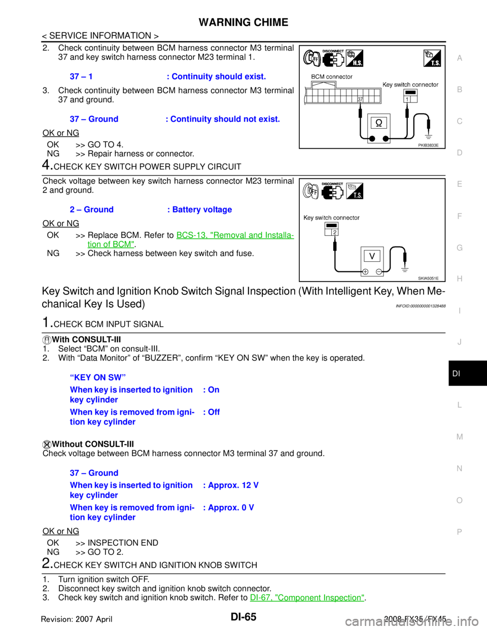
2. Check continuity between BCM harness connector M3 terminal 37 and key switch harness connector M23 terminal 1.
3. Check continuity between BCM harness connector M3 terminal 37 and ground.
OK or NG
OK >> GO TO 4.
NG >> Repair harness or connector.
4.CHECK KEY SWITCH POWER SUPPLY CIRCUIT
Check voltage between key switch harness connector M23 terminal
2 and ground.
OK or NG
OK >> Replace BCM. Refer to BCS-13, "Removal and Installa-
tion of BCM".
NG >> Check harness between key switch and fuse.
Key Switch and Ignition Knob Switch Signal Inspection (With Intelligent Key, When Me-
chanical Key Is Used)
INFOID:0000000001328488
1.CHECK BCM INPUT SIGNAL
With CONSULT-III
1. Select “BCM” on consult-III.
2. With “Data Monitor” of “BUZZER”, conf irm “KEY ON SW” when the key is operated.
Without CONSULT-III
Check voltage between BCM harness connector M3 terminal 37 and ground.
OK or NG
OK >> INSPECTION END
NG >> GO TO 2.
2.CHECK KEY SWITCH AND IG NITION KNOB SWITCH
1. Turn ignition switch OFF.
2. Disconnect key switch and i gnition knob switch connector.
3. Check key switch and ignition knob switch. Refer to DI-67, "
Component Inspection".
37 – 1 : Continuity should exist.
37 – Ground : Continuity should not exist.
PKIB3833E
2 – Ground : Battery voltage
SKIA5051E
“KEY ON SW”
When key is inserted to ignition
key cylinder
: On
When key is removed from igni-
tion key cylinder : Off
37 – Ground
When key is inserted to ignition
key cylinder: Approx. 12 V
When key is removed from igni-
tion key cylinder : Approx. 0 V
3AA93ABC3ACD3AC03ACA3AC03AC63AC53A913A773A893A873A873A8E3A773A983AC73AC93AC03AC3
3A893A873A873A8F3A773A9D3AAF3A8A3A8C3A863A9D3AAF3A8B3A8C
Page 1192 of 3924

DI-66
< SERVICE INFORMATION >
WARNING CHIME
OK or NG
OK >> GO TO 3.
NG >> Replace key switch and ignition knob switch.
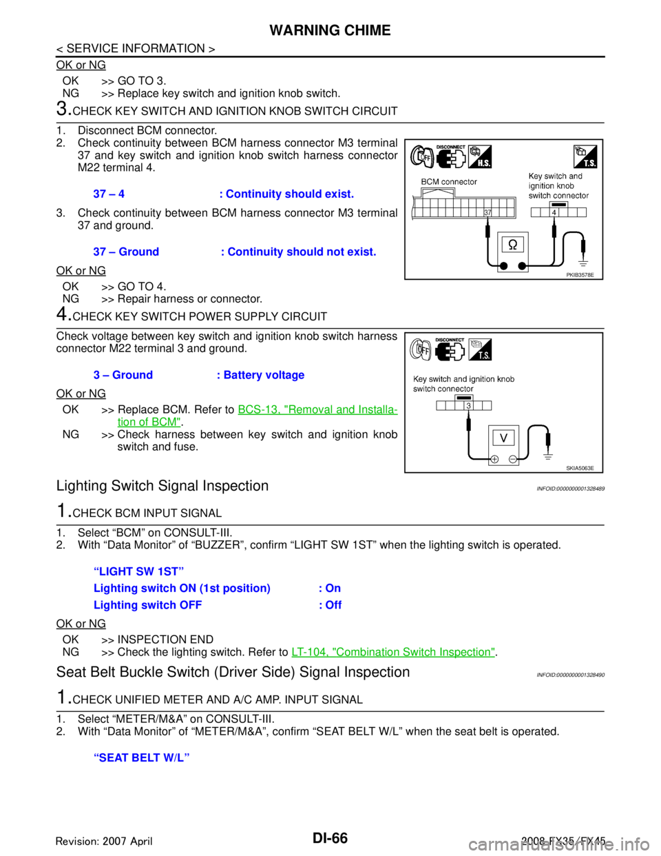
3.CHECK KEY SWITCH AND IGNITION KNOB SWITCH CIRCUIT
1. Disconnect BCM connector.
2. Check continuity between BCM harness connector M3 terminal 37 and key switch and ignition knob switch harness connector
M22 terminal 4.
3. Check continuity between BCM harness connector M3 terminal 37 and ground.
OK or NG
OK >> GO TO 4.
NG >> Repair harness or connector.
4.CHECK KEY SWITCH PO WER SUPPLY CIRCUIT
Check voltage between key switch and ignition knob switch harness
connector M22 terminal 3 and ground.
OK or NG
OK >> Replace BCM. Refer to BCS-13, "Removal and Installa-
tion of BCM".
NG >> Check harness between key switch and ignition knob switch and fuse.
Lighting Switch Signal InspectionINFOID:0000000001328489
1.CHECK BCM INPUT SIGNAL
1. Select “BCM” on CONSULT-III.
2. With “Data Monitor” of “BUZZER”, confirm “LIG HT SW 1ST” when the lighting switch is operated.
OK or NG
OK >> INSPECTION END
NG >> Check the lighting switch. Refer to LT-104, "
Combination Switch Inspection".
Seat Belt Buckle Switch (Driver Side) Signal InspectionINFOID:0000000001328490
1.CHECK UNIFIED METER AND A/C AMP. INPUT SIGNAL
1. Select “METER/M&A” on CONSULT-III.
2. With “Data Monitor” of “MET ER/M&A”, confirm “SEAT BELT W/L” when the seat belt is operated.
37 – 4 : Continuity should exist.
37 – Ground : Continuity should not exist.
PKIB3578E
3 – Ground : Battery voltage
SKIA5063E
“LIGHT SW 1ST”
Lighting switch ON (1st position) : On
Lighting switch OFF : Off
“SEAT BELT W/L”
3AA93ABC3ACD3AC03ACA3AC03AC63AC53A913A773A893A873A873A8E3A773A983AC73AC93AC03AC3
3A893A873A873A8F3A773A9D3AAF3A8A3A8C3A863A9D3AAF3A8B3A8C
Page 1649 of 3924
![INFINITI FX35 2008 Service Manual
DTC P0506 ISC SYSTEMEC-409
< SERVICE INFORMATION > [VQ35DE]
C
D
E
F
G H
I
J
K L
M A
EC
NP
O
DTC P0506 ISC SYSTEM
DescriptionINFOID:0000000001326246
NOTE:
If DTC P0506 is displayed with ot
her DTC, fi INFINITI FX35 2008 Service Manual
DTC P0506 ISC SYSTEMEC-409
< SERVICE INFORMATION > [VQ35DE]
C
D
E
F
G H
I
J
K L
M A
EC
NP
O
DTC P0506 ISC SYSTEM
DescriptionINFOID:0000000001326246
NOTE:
If DTC P0506 is displayed with ot
her DTC, fi](/manual-img/42/57017/w960_57017-1648.png)
DTC P0506 ISC SYSTEMEC-409
< SERVICE INFORMATION > [VQ35DE]
C
D
E
F
G H
I
J
K L
M A
EC
NP
O
DTC P0506 ISC SYSTEM
DescriptionINFOID:0000000001326246
NOTE:
If DTC P0506 is displayed with ot
her DTC, first perform the trouble diagnosis for the other DTC.
The ECM controls the engine idle speed to a specified leve l through the fine adjustment of the air, which is let
into the intake manifold, by operating the electric thrott le control actuator. The operating of the throttle valve is
varied to allow for optimum control of the engine idli ng speed. The crankshaft position sensor (POS) detects
the actual engine speed and sends a signal to the ECM.
The ECM controls the electric throttle control actuator so that the engine speed coincides with the target value
memorized in the ECM. The target engine speed is t he lowest speed at which the engine can operate steadily.
The optimum value stored in the ECM is determined by taking into consideration various engine conditions,
such as during warming up, deceleration, and engine load (air conditioner, power steering and cooling fan
operation, etc.).
On Board Diagnosis LogicINFOID:0000000001326247
DTC Confirmation ProcedureINFOID:0000000001326248
NOTE:
If DTC Confirmation Procedure has been previously conduc ted, always turn ignition switch OFF and wait at
least 10 seconds before conducting the next test.
If the target idle speed is out of the specified value, perform, EC-85, "
Idle Air Volume Learning",
before conducting DTC Confirmation Procedure. For the target idle speed, refer to the EC-593
.
TESTING CONDITION:
Before performing the following procedure, confirm that battery voltage is more than 11V at idle.
Always perform the test at a temperature above −10 °C(14 °F).
1. Start engine and warm it up to normal operating temperature.
2. Turn ignition switch OFF and wait at least 10 seconds.
3. Start engine and run it for at least 1 minute at idle speed.
4. Check 1st trip DTC.
5. If 1st trip DTC is detected, go to EC-409, "
Diagnosis Procedure".
Diagnosis ProcedureINFOID:0000000001326249
1.CHECK INTAKE AIR LEAK
1. Start engine and let it idle.
2. Listen for an intake air leak after the mass air flow sensor.
OK or NG
OK >> GO TO 2.
NG >> Discover air leak location and repair.
2.REPLACE ECM
1. Stop engine.
2. Replace ECM.
3. Perform initialization of IVIS(NATS) system and registration of all IVIS(NATS) ignition key IDs.
Refer to BL-187, "
ECM Re-Communicating Function".
4. Perform EC-84, "
VIN Registration".
5. Perform EC-85, "
Accelerator Pedal Released Position Learning".
6. Perform EC-85, "
Throttle Valve Closed Position Learning".
7. Perform EC-85, "
Idle Air Volume Learning".
DTC No. Trouble diagnosis name DTC detecting condition Possible cause
P0506
0506 Idle speed control sys-
tem (ISC) RPM lower
than expected The idle speed is less than the target idle speed
by 100 rpm or more.
Electric throttle control actuator
Intake air leak
3AA93ABC3ACD3AC03ACA3AC03AC63AC53A913A773A893A873A873A8E3A773A983AC73AC93AC03AC3
3A893A873A873A8F3A773A9D3AAF3A8A3A8C3A863A9D3AAF3A8B3A8C
Page 1651 of 3924
![INFINITI FX35 2008 Service Manual
DTC P0507 ISC SYSTEMEC-411
< SERVICE INFORMATION > [VQ35DE]
C
D
E
F
G H
I
J
K L
M A
EC
NP
O
DTC P0507 ISC SYSTEM
DescriptionINFOID:0000000001326250
NOTE:
If DTC P0507 is displayed with ot
her DTC, fi INFINITI FX35 2008 Service Manual
DTC P0507 ISC SYSTEMEC-411
< SERVICE INFORMATION > [VQ35DE]
C
D
E
F
G H
I
J
K L
M A
EC
NP
O
DTC P0507 ISC SYSTEM
DescriptionINFOID:0000000001326250
NOTE:
If DTC P0507 is displayed with ot
her DTC, fi](/manual-img/42/57017/w960_57017-1650.png)
DTC P0507 ISC SYSTEMEC-411
< SERVICE INFORMATION > [VQ35DE]
C
D
E
F
G H
I
J
K L
M A
EC
NP
O
DTC P0507 ISC SYSTEM
DescriptionINFOID:0000000001326250
NOTE:
If DTC P0507 is displayed with ot
her DTC, first perform the trouble diagnosis for the other DTC.
The ECM controls the engine idle speed to a specified leve l through the fine adjustment of the air, which is let
into the intake manifold, by operating the electric thrott le control actuator. The operating of the throttle valve is
varied to allow for optimum control of the engine idli ng speed. The crankshaft position sensor (POS) detects
the actual engine speed and sends a signal to the ECM.
The ECM controls the electric throttle control actuator so that the engine speed coincides with the target value
memorized in the ECM. The target engine speed is t he lowest speed at which the engine can operate steadily.
The optimum value stored in the ECM is determined by taking into consideration various engine conditions,
such as during warming up, deceleration, and engine load (air conditioner, power steering and cooling fan
operation, etc.).
On Board Diagnosis LogicINFOID:0000000001326251
DTC Confirmation ProcedureINFOID:0000000001326252
NOTE:
If DTC Confirmation Procedure has been previously conduc ted, always turn ignition switch OFF and wait at
least 10 seconds before conducting the next test.
If the target idle speed is out of the specified value, perform, EC-85, "
Idle Air Volume Learning",
before conducting DTC Confirmation Procedure. For the target idle speed, refer to the EC-593
.
TESTING CONDITION:
Before performing the following procedure, confirm that battery voltage is more than 11V at idle.
Always perform the test at a temperature above −10 °C(14 °F).
1. Start engine and warm it up to normal operating temperature.
2. Turn ignition switch OFF and wait at least 10 seconds.
3. Start engine and run it for at least 1 minute at idle speed.
4. Check 1st trip DTC.
5. If 1st trip DTC is detected, go to EC-411, "
Diagnosis Procedure".
Diagnosis ProcedureINFOID:0000000001326253
1.CHECK PCV HOSE CONNECTION
Confirm that PCV hose is connected correctly.
OK or NG
OK >> GO TO 2.
NG >> Repair or replace.
2.CHECK INTAKE AIR LEAK
1. Start engine and let it idle.
2. Listen for an intake air leak after the mass air flow sensor.
OK or NG
OK >> GO TO 3.
NG >> Discover air leak location and repair.
3.REPLACE ECM
1. Stop engine.
2. Replace ECM.
3. Perform initialization of IVIS(NATS) system and registration of all IVIS(NATS) ignition key IDs.
DTC No. Trouble diagnosis name DTC detecting condition Possible cause
P0507
0507 Idle speed control sys-
tem (ISC) RPM higher
than expected The idle speed is more than the target idle
speed by 200 rpm or more. Electric throttle control actuator
Intake air leak
PCV system
3AA93ABC3ACD3AC03ACA3AC03AC63AC53A913A773A893A873A873A8E3A773A983AC73AC93AC03AC3
3A893A873A873A8F3A773A9D3AAF3A8A3A8C3A863A9D3AAF3A8B3A8C
Page 2234 of 3924
![INFINITI FX35 2008 Service Manual
EC-994
< SERVICE INFORMATION >[VK45DE]
DTC P0506 ISC SYSTEM
DTC P0506 ISC SYSTEM
DescriptionINFOID:0000000001326843
NOTE:
If DTC P0506 is displayed with ot
her DTC, first perform the trouble diagnosi INFINITI FX35 2008 Service Manual
EC-994
< SERVICE INFORMATION >[VK45DE]
DTC P0506 ISC SYSTEM
DTC P0506 ISC SYSTEM
DescriptionINFOID:0000000001326843
NOTE:
If DTC P0506 is displayed with ot
her DTC, first perform the trouble diagnosi](/manual-img/42/57017/w960_57017-2233.png)
EC-994
< SERVICE INFORMATION >[VK45DE]
DTC P0506 ISC SYSTEM
DTC P0506 ISC SYSTEM
DescriptionINFOID:0000000001326843
NOTE:
If DTC P0506 is displayed with ot
her DTC, first perform the trouble diagnosis for the other DTC.
The ECM controls the engine idle speed to a specified leve l through the fine adjustment of the air, which is let
into the intake manifold, by operating the electric thrott le control actuator. The operating of the throttle valve is
varied to allow for optimum control of the engine idli ng speed. The crankshaft position sensor (POS) detects
the actual engine speed and sends a signal to the ECM.
The ECM controls the electric throttle control actuator so that the engine speed coincides with the target value
memorized in the ECM. The target engine speed is t he lowest speed at which the engine can operate steadily.
The optimum value stored in the ECM is determined by taking into consideration various engine conditions,
such as during warming up, deceleration, and engine l oad (air conditioner, power steering and cooling fan
operation, etc.).
On Board Diagn osis LogicINFOID:0000000001326844
DTC Confirmation ProcedureINFOID:0000000001326845
NOTE:
If DTC Confirmation Procedure has been previously conduc ted, always turn ignition switch OFF and wait at
least 10 seconds before conducting the next test.
If the target idle speed is out of the specified value, perform EC-663, "
Idle Air Volume Learning",
before conducting DTC Confirmation Procedure. For the target idle speed, refer to the EC-1196
.
TESTING CONDITION:
Before performing the following procedure, confirm that battery voltage is more than 11V at idle.
Always perform the test at a temperature above −10 °C(14 °F).
WITH CONSULT-III
1. Open engine hood.
2. Start engine and warm it up to normal operating temperature.
3. Turn ignition switch OFF and wait at least 10 seconds.
4. Start engine and run it for at least 1 minute at idle speed.
5. Check 1st trip DTC.
6. If 1st trip DTC is detected, go to EC-994, "
Diagnosis Procedure".
Diagnosis ProcedureINFOID:0000000001326846
1.CHECK INTAKE AIR LEAK
1. Start engine and let it idle.
2. Listen for an intake air leak after the mass air flow sensor.
OK or NG
OK >> GO TO 2.
NG >> Discover air leak location and repair.
2.REPLACE ECM
1. Stop engine.
2. Replace ECM.
3. Perform initialization of IVIS (NATS) system and regist ration of all IVIS (NATS) ignition key IDs. Refer to
BL-187, "
ECM Re-Communicating Function".
4. Perform EC-662, "
VIN Registration".
5. Perform EC-662, "
Accelerator Pedal Released Position Learning".
DTC No. Trouble diagnosis name DTC detecting condition Possible cause
P0506
0506 Idle speed control sys-
tem RPM lower than ex-
pected The idle speed is less than the target idle speed
by 100 rpm or more.
Electric throttle control actuator
Intake air leak
3AA93ABC3ACD3AC03ACA3AC03AC63AC53A913A773A893A873A873A8E3A773A983AC73AC93AC03AC3
3A893A873A873A8F3A773A9D3AAF3A8A3A8C3A863A9D3AAF3A8B3A8C
Page 2488 of 3924
![INFINITI FX35 2008 Service Manual
EM-4
< SERVICE INFORMATION >[VQ35DE]
PRECAUTIONS
SERVICE INFORMATION
PRECAUTIONS
Precaution Necessary for Steering W
heel Rotation After Battery Disconnect
INFOID:0000000001524592
NOTE:
• This Proc INFINITI FX35 2008 Service Manual
EM-4
< SERVICE INFORMATION >[VQ35DE]
PRECAUTIONS
SERVICE INFORMATION
PRECAUTIONS
Precaution Necessary for Steering W
heel Rotation After Battery Disconnect
INFOID:0000000001524592
NOTE:
• This Proc](/manual-img/42/57017/w960_57017-2487.png)
EM-4
< SERVICE INFORMATION >[VQ35DE]
PRECAUTIONS
SERVICE INFORMATION
PRECAUTIONS
Precaution Necessary for Steering W
heel Rotation After Battery Disconnect
INFOID:0000000001524592
NOTE:
• This Procedure is applied only to models with In telligent Key system and NVIS/IVIS (NISSAN/INFINITI
VEHICLE IMMOBILIZER SYSTEM - NATS).
Remove and install all control units after disconnecting both battery cables with the ignition knob in the ″LOCK ″ position.
Always use CONSULT-III to perform self-diagnosis as a part of each function inspection after finishing work.
If DTC is detected, perform trouble diagnosis according to self-diagnostic results.
For models equipped with the Intelligent Key system and NVIS /IVIS, an electrically controlled steering lock
mechanism is adopted on the key cylinder.
For this reason, if the battery is disconnected or if the battery is discharged, the steering wheel will lock and
steering wheel rotation will become impossible.
If steering wheel rotation is required when battery pow er is interrupted, follow the procedure below before
starting the repair operation.
OPERATION PROCEDURE
1. Connect both battery cables. NOTE:
Supply power using jumper cables if battery is discharged.
2. Use the Intelligent Key or mechanical key to turn the ignition switch to the ″ACC ″ position. At this time, the
steering lock will be released.
3. Disconnect both battery cables. The steering lock will remain released and the steering wheel can be
rotated.
4. Perform the necessary repair operation.
5. When the repair work is completed, return the ignition switch to the ″LOCK ″ position before connecting
the battery cables. (At this time, the steering lock mechanism will engage.)
6. Perform a self-diagnosis check of all control units using CONSULT-III.
Precaution for Drain Engine Coolant and Engine OilINFOID:0000000001325693
Drain engine coolant and engine oil when the engine is cooled.
Precaution for Disconnecting Fuel PipingINFOID:0000000001325694
Before starting work, make sure no fire or spark producing items are in the work area.
Release fuel pressure before disconnecting and disassembly.
After disconnecting pipes, plug openings to stop fuel leakage.
Precaution for Removal and DisassemblyINFOID:0000000001325695
When instructed to use SST, use specified tools. Always be careful to work safely, avoid forceful or unin-
structed operations.
Exercise maximum care to avoid damage to mating or sliding surfaces.
Cover openings of engine system with a tape or equival ent, if necessary, to seal out foreign materials.
Mark and arrange disassembly parts in an organi zed way for easy troubleshooting and re-assembly.
When loosening nuts and bolts, as a basic rule, star t with the one furthest outside, then the one diagonally
opposite, and so on. If the order of loosening is specified, do exactly as specified. Power tools may be used
in the step.
Precaution for Inspection, Repair and ReplacementINFOID:0000000001325696
Before repairing or replacing, thoroughly inspect parts. Inspect new replacement parts in the same way, and
replace if necessary.
3AA93ABC3ACD3AC03ACA3AC03AC63AC53A913A773A893A873A873A8E3A773A983AC73AC93AC03AC3
3A893A873A873A8F3A773A9D3AAF3A8A3A8C3A863A9D3AAF3A8B3A8C