2008 INFINITI FX35 fuse
[x] Cancel search: fusePage 1192 of 3924
DI-66
< SERVICE INFORMATION >
WARNING CHIME
OK or NG
OK >> GO TO 3.
NG >> Replace key switch and ignition knob switch.
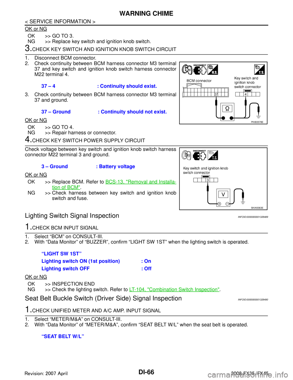
3.CHECK KEY SWITCH AND IGNITION KNOB SWITCH CIRCUIT
1. Disconnect BCM connector.
2. Check continuity between BCM harness connector M3 terminal 37 and key switch and ignition knob switch harness connector
M22 terminal 4.
3. Check continuity between BCM harness connector M3 terminal 37 and ground.
OK or NG
OK >> GO TO 4.
NG >> Repair harness or connector.
4.CHECK KEY SWITCH PO WER SUPPLY CIRCUIT
Check voltage between key switch and ignition knob switch harness
connector M22 terminal 3 and ground.
OK or NG
OK >> Replace BCM. Refer to BCS-13, "Removal and Installa-
tion of BCM".
NG >> Check harness between key switch and ignition knob switch and fuse.
Lighting Switch Signal InspectionINFOID:0000000001328489
1.CHECK BCM INPUT SIGNAL
1. Select “BCM” on CONSULT-III.
2. With “Data Monitor” of “BUZZER”, confirm “LIG HT SW 1ST” when the lighting switch is operated.
OK or NG
OK >> INSPECTION END
NG >> Check the lighting switch. Refer to LT-104, "
Combination Switch Inspection".
Seat Belt Buckle Switch (Driver Side) Signal InspectionINFOID:0000000001328490
1.CHECK UNIFIED METER AND A/C AMP. INPUT SIGNAL
1. Select “METER/M&A” on CONSULT-III.
2. With “Data Monitor” of “MET ER/M&A”, confirm “SEAT BELT W/L” when the seat belt is operated.
37 – 4 : Continuity should exist.
37 – Ground : Continuity should not exist.
PKIB3578E
3 – Ground : Battery voltage
SKIA5063E
“LIGHT SW 1ST”
Lighting switch ON (1st position) : On
Lighting switch OFF : Off
“SEAT BELT W/L”
3AA93ABC3ACD3AC03ACA3AC03AC63AC53A913A773A893A873A873A8E3A773A983AC73AC93AC03AC3
3A893A873A873A8F3A773A9D3AAF3A8A3A8C3A863A9D3AAF3A8B3A8C
Page 1197 of 3924
LANE DEPARTURE WARNING SYSTEMDI-71
< SERVICE INFORMATION >
C
DE
F
G H
I
J
L
M A
B
DI
N
O P
NOTE:
*: This indicates in a few seconds for the system check during ignition switch ON.
POWER SUPPLY AND GROUND CIRCUIT
With the ignition switch in the ON or START position, power is supplied
through 10A fuse [No. 12, located in the fuse block (J/B)]
to LDW camera unit terminal 1.
Ground is supplied
to LDW camera unit terminals 6 and 12
through grounds M45, M85 and M35.
Action TestINFOID:0000000001328494
LDW SYSTEM RUNNING TEST
WARNING:
Be careful when performing road test.
Understand “Precautions” and “System Description” well before the road test. Refer to DI-69, "
Pre-
caution for Lane Departure Warning (LDW) system" and DI-69, "System Description".
Function Check
Check the LDW system operation according to the c ondition that the warning function works. Refer to DI-69,
"System Description".
Camera Aiming AdjustmentINFOID:0000000001328495
OUTLINE
Adjust the camera aiming every time the LDW camera unit is removed or installed.
CAUTION:
Place the vehicle on the level ground when the camera aiming adjustment is operated.
Follow the CONSULT-III when ad justing the camera aiming. (Camera aiming adjustment cannot be
operated without CONSULT-III.)
PREPARATION
Keep all tires inflated to correct pressures. Adjust the tire pressure to the specified pressure value.
There is no-load in vehicle. Check if coolant, engine oil are filled up to correct level and fuel tank is full.
Shift the gear into “P” position and release the parking brake.
Clean the windshield.
NOTE:
Do not place anything reflective on t he upper surface of instrument panel.
TARGET SETTING
Preparation Aiming Adjustment Jig
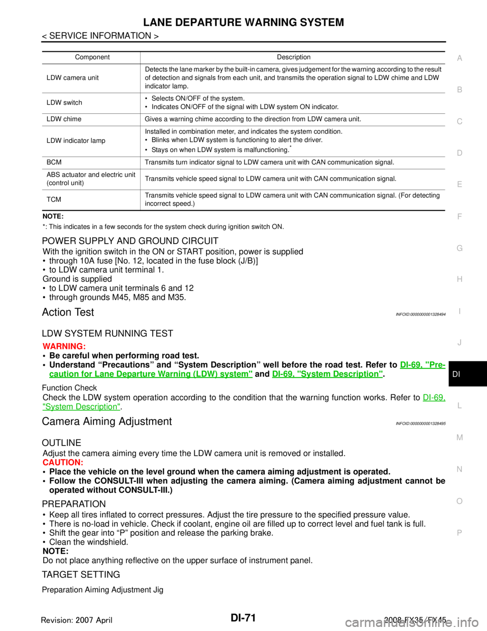
Component Description
LDW camera unit Detects the lane marker by the built-in camera, gives judgement for the warning according to the result
of detection and signals from each unit, and transmits the operation signal to LDW chime and LDW
indicator lamp.
LDW switch Selects ON/OFF of the system.
Indicates ON/OFF of the signal with LDW system ON indicator.
LDW chime Gives a warning chime according to the direction from LDW camera unit.
LDW indicator lamp Installed in combination meter, and indicates the system condition.
Blinks when LDW system is functioning to alert the driver.
Stays on when LDW system is malfunctioning.
*
BCM Transmits turn indicator signal to LDW camera unit with CAN communication signal.
ABS actuator and electric unit
(control unit)
Transmits vehicle speed signal to LDW camera unit with CAN communication signal.
TCM Transmits vehicle speed signal to LDW camera unit with CAN communication signal. (For detecting
incorrect speed.)
3AA93ABC3ACD3AC03ACA3AC03AC63AC53A913A773A893A873A873A8E3A773A983AC73AC93AC03AC3
3A893A873A873A8F3A773A9D3AAF3A8A3A8C3A863A9D3AAF3A8B3A8C
Page 1210 of 3924
DI-84
< SERVICE INFORMATION >
LANE DEPARTURE WARNING SYSTEM
Preliminary Check
INFOID:0000000001328502
1.CHECK CAMERA LENS AND WINDSHIELD
Are camera lens and windshield contaminated with foreign materials?
YES >> Clean camera lens and windshield.
NO >> GO TO 2.
2.CHECK CAMERA UNIT IN STALLATION CONDITION
Check camera unit installation condition (installat ion position, properly tightened, a bent bracket).
OK or NG
OK >> GO TO 3.
NG >> Install camera unit properly, and adjust camera aiming. Refer to DI-71, "
Camera Aiming Adjust-
ment".
3.CHECK VEHICLE HEIGHT
Check vehicle height. Refer to GI-47, "
Dimensions".
Is vehicle height appropriate?
OK >> GO TO 4.
NG >> Repair vehicle to appropriate height.
4.CHECK LDW CAMERA UNIT (CONSULT-III)
Perform self-diagnosis of LDW camera unit. Refer to DI-81, "
CONSULT-III Function (LDW)".
Self
-diagnosis results
No malfunction detected >> GO TO 5.
Malfunction detected >> Check applicable parts, and repair or replace corresponding parts.
5.CHECK COMBINATION METER
Check combination meter function.
Do speedometer and turn signal indicator normal function?
YES >> INSPECTION END
NO >> Check combination meter. Refer to DI-15, "
Trouble Diagnosis".
Power Supply and Ground Circuit InspectionINFOID:0000000001328503
1.CHECK FUSE
Check for blown LDW camera unit fuse.
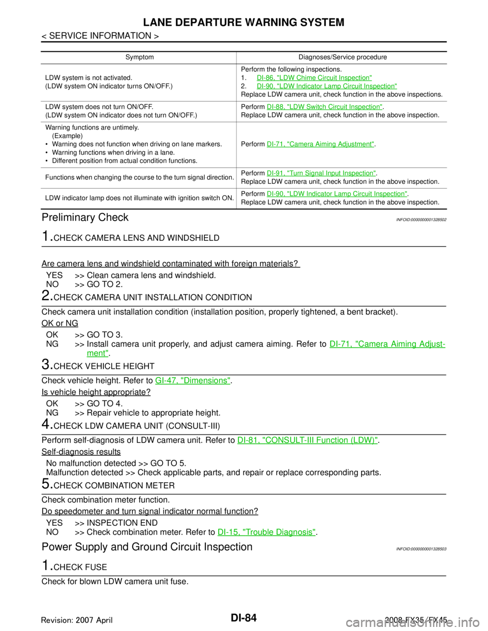
Symptom Diagnoses/Service procedure
LDW system is not activated.
(LDW system ON indicator turns ON/OFF.) Perform the following inspections.
1.
DI-86, "
LDW Chime Circuit Inspection"
2.DI-90, "LDW Indicator Lamp Circuit Inspection"
Replace LDW camera unit, check function in the above inspections.
LDW system does not turn ON/OFF.
(LDW system ON indicator does not turn ON/OFF.) Perform
DI-88, "
LDW Switch Circuit Inspection".
Replace LDW camera unit, check function in the above inspection.
Warning functions are untimely. (Example)
Warning does not function when driving on lane markers.
Warning functions when driving in a lane.
Different position from actual condition functions. Perform
DI-71, "
Camera Aiming Adjustment".
Functions when changing the course to the turn signal direction. Perform
DI-91, "
Turn Signal Input Inspection".
Replace LDW camera unit, check function in the above inspection.
LDW indicator lamp does not illuminate with ignition switch ON. Perform
DI-90, "
LDW Indicator Lamp Circuit Inspection".
Replace LDW camera unit, check function in the above inspection.
3AA93ABC3ACD3AC03ACA3AC03AC63AC53A913A773A893A873A873A8E3A773A983AC73AC93AC03AC3
3A893A873A873A8F3A773A9D3AAF3A8A3A8C3A863A9D3AAF3A8B3A8C
Page 1211 of 3924
LANE DEPARTURE WARNING SYSTEMDI-85
< SERVICE INFORMATION >
C
DE
F
G H
I
J
L
M A
B
DI
N
O P
OK or NG
OK >> GO TO 2.
NG >> Be sure to eliminate cause of malfunction before installing new fuse. Refer to PG-77, "
Terminal
Arrangement".
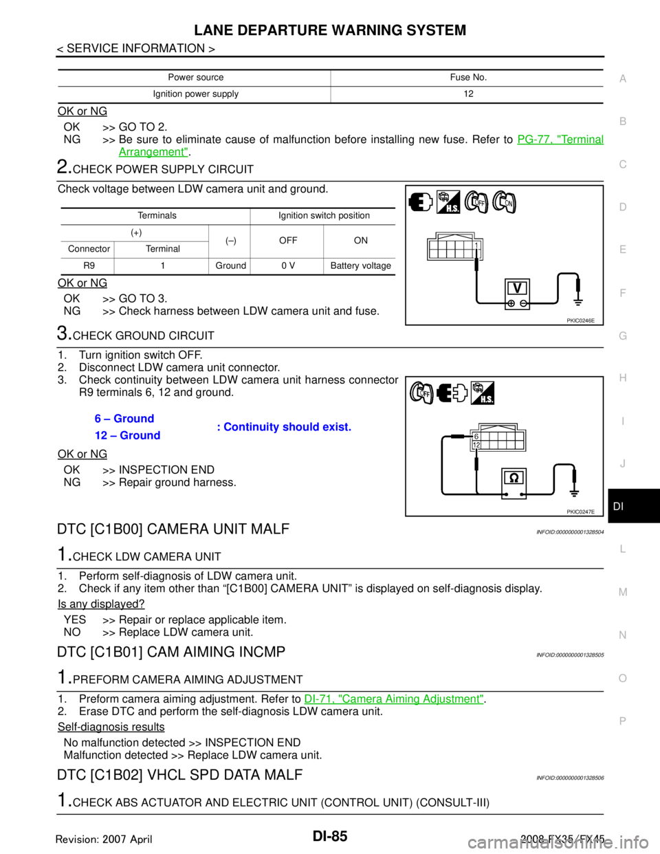
2.CHECK POWER SUPPLY CIRCUIT
Check voltage between LDW camera unit and ground.
OK or NG
OK >> GO TO 3.
NG >> Check harness between LDW camera unit and fuse.
3.CHECK GROUND CIRCUIT
1. Turn ignition switch OFF.
2. Disconnect LDW camera unit connector.
3. Check continuity between LDW camera unit harness connector R9 terminals 6, 12 and ground.
OK or NG
OK >> INSPECTION END
NG >> Repair ground harness.
DTC [C1B00] CAMERA UNIT MALFINFOID:0000000001328504
1.CHECK LDW CAMERA UNIT
1. Perform self-diagnosis of LDW camera unit.
2. Check if any item other than “[C1B00] CAMERA UNIT” is displayed on self-diagnosis display.
Is any displayed?
YES >> Repair or replace applicable item.
NO >> Replace LDW camera unit.
DTC [C1B01] CAM AIMING INCMPINFOID:0000000001328505
1.PREFORM CAMERA AIMING ADJUSTMENT
1. Preform camera aiming adjustment. Refer to DI-71, "
Camera Aiming Adjustment".
2. Erase DTC and perform the self-diagnosis LDW camera unit.
Self
-diagnosis results
No malfunction detected >> INSPECTION END
Malfunction detected >> Replace LDW camera unit.
DTC [C1B02] VHCL SPD DATA MALFINFOID:0000000001328506
1.CHECK ABS ACTUATOR AND ELECTRIC UNIT (CONTROL UNIT) (CONSULT-III)
Power source Fuse No.
Ignition power supply 12
Terminals Ignition switch position
(+) (–) OFF ON
Connector Terminal
R9 1 Ground 0 V Battery voltage
PKIC0246E
6 – Ground : Continuity should exist.
12 – Ground
PKIC0247E
3AA93ABC3ACD3AC03ACA3AC03AC63AC53A913A773A893A873A873A8E3A773A983AC73AC93AC03AC3
3A893A873A873A8F3A773A9D3AAF3A8A3A8C3A863A9D3AAF3A8B3A8C
Page 1213 of 3924
LANE DEPARTURE WARNING SYSTEMDI-87
< SERVICE INFORMATION >
C
DE
F
G H
I
J
L
M A
B
DI
N
O P
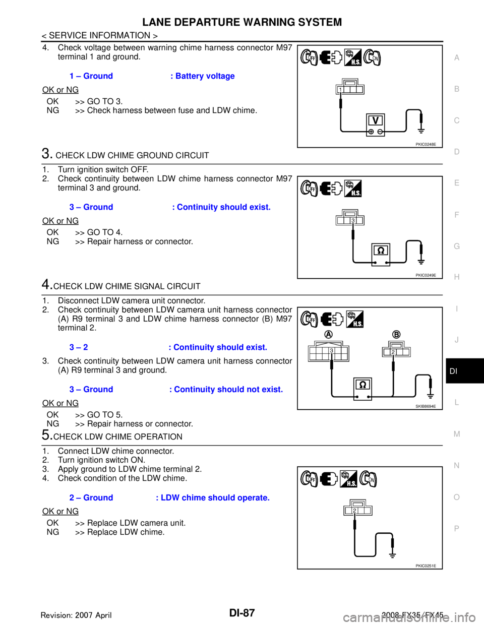
4. Check voltage between warning chime harness connector M97 terminal 1 and ground.
OK or NG
OK >> GO TO 3.
NG >> Check harness between fuse and LDW chime.
3. CHECK LDW CHIME GROUND CIRCUIT
1. Turn ignition switch OFF.
2. Check continuity between LDW chime harness connector M97 terminal 3 and ground.
OK or NG
OK >> GO TO 4.
NG >> Repair harness or connector.
4.CHECK LDW CHIME SIGNAL CIRCUIT
1. Disconnect LDW camera unit connector.
2. Check continuity between LDW camera unit harness connector (A) R9 terminal 3 and LDW chime harness connector (B) M97
terminal 2.
3. Check continuity between LDW camera unit harness connector (A) R9 terminal 3 and ground.
OK or NG
OK >> GO TO 5.
NG >> Repair harness or connector.
5.CHECK LDW CHIME OPERATION
1. Connect LDW chime connector.
2. Turn ignition switch ON.
3. Apply ground to LDW chime terminal 2.
4. Check condition of the LDW chime.
OK or NG
OK >> Replace LDW camera unit.
NG >> Replace LDW chime. 1 – Ground : Battery voltage
PKIC0248E
3 – Ground : Continuity should exist.
PKIC0249E
3 – 2 : Continui
ty should exist.
3 – Ground : Continuity should not exist.
SKIB8694E
2 – Ground : LDW chime should operate.
PKIC0251E
3AA93ABC3ACD3AC03ACA3AC03AC63AC53A913A773A893A873A873A8E3A773A983AC73AC93AC03AC3
3A893A873A873A8F3A773A9D3AAF3A8A3A8C3A863A9D3AAF3A8B3A8C
Page 1215 of 3924

LANE DEPARTURE WARNING SYSTEMDI-89
< SERVICE INFORMATION >
C
DE
F
G H
I
J
L
M A
B
DI
N
O P
6.CHECK OPERATION OF LDW SYSTEM ON INDICATOR
Check LDW system ON indicator oper ation “SYSTEM ON LAMP DRIVE” in “Active Test” mode with CON-
SULT-III.
NOTE:
Perform “SYSTEM ON LAMP DRIVE” when LDW system ON indicator turns OFF.
OK or NG
OK >> Replace LDW camera unit.
NG >> GO TO 7.
7.CHECK LDW SYSTEM ON INDICATOR POWER SUPPLY CIRCUIT
1. Turn ignition switch OFF.
2. Disconnect LDW switch connector.
3. Turn ignition switch ON.
4. Check voltage between LDW switch harness connector M96 ter- minal 3 and ground.
OK or NG
OK >> GO TO 8.
NG >> Check harness between fuse and LDW switch.
8.CHECK LDW SYSTEM ON INDICATOR SIGNAL CIRCUIT
1. Disconnect LDW camera unit connector.
2. Check continuity between LDW camera unit harness connector R9 terminal 4 and LDW switch harness connector M96 terminal
2.
3. Check continuity between LDW camera unit harness connector R9 terminal 4 and ground.
OK or NG
OK >> GO TO 9.
NG >> Repair harness or connector.
9.CHECK LDW SYSTEM ON INDICATOR
1. Connect LDW switch connector.
2. Turn ignition switch ON. “SYSTEM ON LAMP DRIVE”
Select “On” : LDW system ON
indicator illuminates.
Select “Off” : LDW system ON indicator turns OFF.
3 – Ground : Battery voltage
PKIB4705E
4 – 2 : Continuity should exist.
4 – Ground : Continuity should not exist.
PKIB4706E
3AA93ABC3ACD3AC03ACA3AC03AC63AC53A913A773A893A873A873A8E3A773A983AC73AC93AC03AC3
3A893A873A873A8F3A773A9D3AAF3A8A3A8C3A863A9D3AAF3A8B3A8C
Page 1226 of 3924

DI-100
< SERVICE INFORMATION >
REAR VIEW MONITOR
REAR VIEW MONITOR
System DescriptionINFOID:0000000001328529
The rear view monitor is equipped to check the rearward of the vehicle with display when A/T selector leveris in reverse position.
The lines of vehicle sides and the distance from the rear end of the vehicle are provided on display as a
guide. It allows the driver to know the distance bet ween the vehicle and a rearward object, and the width of
the vehicle much easier.
POWER SUPPLY AND GROUND
Power is supplied at all time
through 10A fuse [No. 19, located in fuse block (J/B)]
to rear view camera control unit terminal 1.
When ignition switch is in ACC or ON position, power is supplied
through 10A fuse [No. 6, located in fuse block (J/B)]
to rear view camera control unit terminal 2.
When ignition switch is in ON or START position, power is supplied
through 10A fuse (No. 83, located in IPDM E/R)
to back-up lamp relay terminals 1 and 3.
Ground is supplied
to rear view camera control unit terminal 3
through grounds M35, M45 and M85.
AV COMMUNICATION LINE
Rear view camera control unit is connected to the foll owing units with AV communication line. Each unit trans-
mits/receives data with AV communication line.
NAVI control unit
Display
Display control unit
A/C and AV switch
REAR VIEW CAMERA OPERATION
When A/T selector lever is reverse position, power is supplied
through back-up lamp relay terminal 2
to TCM terminal 7.
Then back-up lamp relay is energized,
from back-up lamp relay terminal 5
to rear view camera control unit terminal 4.
Then, rear view camera control unit is sent camera ON signal
through rear view camera control unit terminal 8
to rear view camera terminal 1.
An image taken by rear view camera is sent
through rear view camera terminals 3 and 4
to rear view camera control unit terminals 10 and 9.
Then an image is sent
through rear view camera control unit terminals 12 and 14
to the display terminals 15 and 16.
An image of rear view will be projected on the display.
Side Distance Guideline
When A/T selector lever is in reverse position, rear view camera control unit is sent rear view camera guideline
image
through rear view camera control unit terminals 12 and 14
to the display terminals 15 and 16.
Rear view camera guideline will be projected on the display.
Display shows image from rear view camera image and rear view camera guideline.
3AA93ABC3ACD3AC03ACA3AC03AC63AC53A913A773A893A873A873A8E3A773A983AC73AC93AC03AC3
3A893A873A873A8F3A773A9D3AAF3A8A3A8C3A863A9D3AAF3A8B3A8C
Page 1234 of 3924
DI-108
< SERVICE INFORMATION >
REAR VIEW MONITOR
6. Select “SAVE”, and confirm the guide line.
7. Select “End”.
8. Select “ADJ GUIDELINE POSITION”.
9. Adjust the guide line selecting “X UP”, “X DOWN”, “Y UP” or “Y DOWN” so that the corrected line can fit
the guide line.
10. Touch “SAVE”, and confirm the guide line.
11. Touch “End” to finish correcting.
Power Supply and Ground Circuit InspectionINFOID:0000000001328536
1.CHECK FUSE
Make sure the fuses for rear view camera control unit is blown.
OK or NG
OK >> GO TO 2.
NG >> Be sure to eliminate cause of malfunction before installing new fuse. Refer to PG-3
.
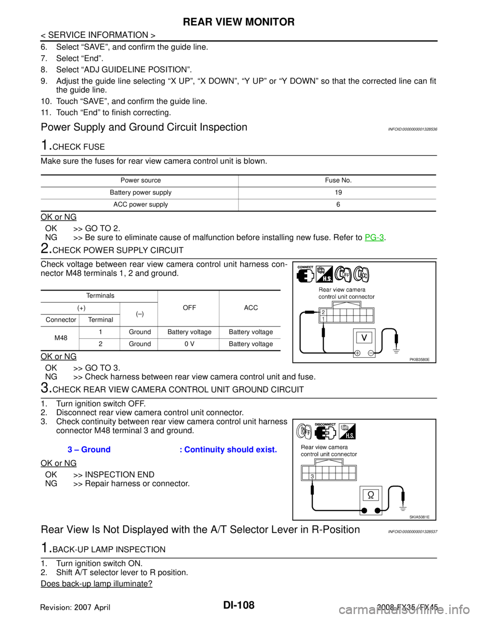
2.CHECK POWER SUPPLY CIRCUIT
Check voltage between rear view camera control unit harness con-
nector M48 terminals 1, 2 and ground.
OK or NG
OK >> GO TO 3.
NG >> Check harness between rear view camera control unit and fuse.
3.CHECK REAR VIEW CAMERA CONTROL UNIT GROUND CIRCUIT
1. Turn ignition switch OFF.
2. Disconnect rear view camera control unit connector.
3. Check continuity between rear view camera control unit harness connector M48 terminal 3 and ground.
OK or NG
OK >> INSPECTION END
NG >> Repair harness or connector.
Rear View Is Not Displayed with the A/T Selector Lever in R-PositionINFOID:0000000001328537
1.BACK-UP LAMP INSPECTION
1. Turn ignition switch ON.
2. Shift A/T selector lever to R position.
Does back-up lamp illuminate?
Power source Fuse No.
Battery power supply 19 ACC power supply 6
Te r m i n a l s OFF ACC
(+)
(–)
Connector Terminal
M48 1 Ground Battery voltage Battery voltage
2 Ground 0 V Battery voltage
PKIB3580E
3 – Ground : Continuity should exist.
SKIA5081E
3AA93ABC3ACD3AC03ACA3AC03AC63AC53A913A773A893A873A873A8E3A773A983AC73AC93AC03AC3
3A893A873A873A8F3A773A9D3AAF3A8A3A8C3A863A9D3AAF3A8B3A8C