2008 INFINITI FX35 fuse
[x] Cancel search: fusePage 1143 of 3924
COMBINATION METERSDI-17
< SERVICE INFORMATION >
C
DE
F
G H
I
J
L
M A
B
DI
N
O P
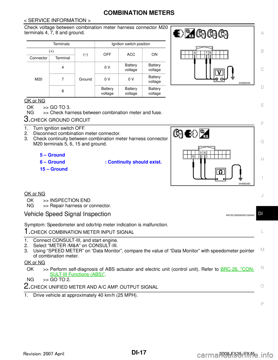
Check voltage between combination meter harness connector M20
terminals 4, 7, 8 and ground.
OK or NG
OK >> GO TO 3.
NG >> Check harness between combination meter and fuse.
3.CHECK GROUND CIRCUIT
1. Turn ignition switch OFF.
2. Disconnect combination meter connector.
3. Check continuity between combination meter harness connector M20 terminals 5, 6, 15 and ground.
OK or NG
OK >> INSPECTION END
NG >> Repair harness or connector.
Vehicle Speed Signal InspectionINFOID:0000000001328445
Symptom: Speedometer and odo/trip meter indication is malfunction.
1.CHECK COMBINATION METER INPUT SIGNAL
1. Connect CONSULT-III, and start engine.
2. Select “METER /M&A” on CONSULT-III.
3. Using “SPEED METER” on “Data Moni tor”, compare the value of “Data Monitor” with speedometer pointer
of combination meter.
OK or NG
OK >> Perform self-diagnosis of ABS actuator and electric unit (control unit). Refer to BRC-26, "CON-
SULT-III Functions (ABS)".
NG >> GO TO 2.
2.CHECK UNIFIED METER AND A/ C AMP. OUTPUT SIGNAL
1. Drive vehicle at approximately 40 km/h (25 MPH).
Terminals Ignition switch position
(+) (–) OFF ACC ON
Connector Terminal
M20 4
Ground 0 V
Battery
voltage Battery
voltage
70 V0 V Battery
voltage
8 Battery
voltage Battery
voltage Battery
voltage
SKIB8525E
5 – Ground
: Continuity should exist.
6 – Ground
15 – Ground
SKIB8526E
3AA93ABC3ACD3AC03ACA3AC03AC63AC53A913A773A893A873A873A8E3A773A983AC73AC93AC03AC3
3A893A873A873A8F3A773A9D3AAF3A8A3A8C3A863A9D3AAF3A8B3A8C
Page 1155 of 3924

UNIFIED METER AND A/C AMPDI-29
< SERVICE INFORMATION >
C
DE
F
G H
I
J
L
M A
B
DI
N
O P
NOTE:
Monitored item that does not match the vehicle is deleted from the display automatically.
*1: It dose not change when fastening or unfastening the passenger seat belt.
*2: Monitor keeps indicating “off” when brake warning lamp is on by the parking brake operation or low brake fluid level.
Power Supply and Gro und Circuit InspectionINFOID:0000000001328459
1.CHECK FUSE
Check for blown unified meter and A/C amp. fuses.
OK or NG
OK >> GO TO 2.
NG >> Be sure to eliminate cause of malfunction before installing new fuse. Refer to PG-3, "
Schematic".
2.CHECK POWER SUPPLY CIRCUIT
OIL W/L [On/Off] X Indicates [On/Off] condition of oil pressure warning lamp.
VDC/TCS IND [On/Off] X Indicates [On/Off] condition of VDC OFF indicator lamp.
ABS W/L [On/Off] X Indicates [On/Off] condition of ABS warning lamp.
SLIP IND [On/Off] X Indicates [On/Off] condition of SLIP indicator lamp.
BRAKE W/L [On/Off]
*2X Indicates [On/Off] condition of brake warning lamp.
KEY G W/L [On/Off] X Indicates [On/Off] condition of key warning lamp (green).
KEY R W/L [On/Off] X Indicates [On/Off] condition of key warning lamp (red).
KEY KNOB W/L [On/Off] X Indicates [On/Off] condition of key knob warning lamp.
M RANGE SW [On/Off] X X Indicates [On/Off] condition of manual mode range switch.
NM RANGE SW [On/Off] X X Indicates [On/Off] condition of except for manual mode range
switch.
AT SFT UP SW [On/Off] X X Indicates [On/Off] condition of A/T shift-up switch.
AT SFT DWN SW [On/Off] X X Indicates [On/Off] condition of A/T shift-down switch.
BRAKE SW [On/Off] X Indicates [On/Off] condition of brake switch (stop lamp switch).
AT-M IND [On/Off] X X Indicates [On/Off] condition of A/T manual mode indicator.
AT-M GEAR [5-1] X X Indicates [5-1] condition of A/T manual mode gear position.
P RANGE IND [On/Off] X X Indicates [On/Off] condition of A/T shift P range indicator.
R RANGE IND [On/Off] X X Indicates [On/Off] condition of A/T shift R range indicator.
N RANGE IND [On/Off] X X Indicates [On/Off] condition of A/T shift N range indicator.
D RANGE IND [On/Off] X X Indicates [On/Off] condition of A/T shift D range indicator.
AT CHECK W/L X Indicates [On/Off] cond ition of AT CHECK warning lamp.
CRUISE IND [On/Off] X Indicates [On/Off] condition of CRUISE indicator lamp.
SET IND [On/Off] X Indicates [On/Off] condition of SET indicator lamp.
CRUISE W/L [On/Off] X Indicates [On/Of f] condition of ICC warning lamp.
4WD LOCK SW [On/Off] X This item is not used for this model. “off” is always displayed.
4WD LOCK IND [On/Off] X This item is not used for this model. “off” is always displayed.
4WD W/L [On/Off] X Indicates [On/Off] condition of AWD warning lamp.
RR COMB STATE [OK/NG] X Indicates [OK/NG] condition of rear combination lamp circuit. Display item [Unit]
MAIN
SIGNALS SELECTION
FROM MENU Contents
Power source Fuse No.
Battery power supply 19 ACC power supply 10, 11
Ignition power supply 12
3AA93ABC3ACD3AC03ACA3AC03AC63AC53A913A773A893A873A873A8E3A773A983AC73AC93AC03AC3
3A893A873A873A8F3A773A9D3AAF3A8A3A8C3A863A9D3AAF3A8B3A8C
Page 1156 of 3924
DI-30
< SERVICE INFORMATION >
UNIFIED METER AND A/C AMP
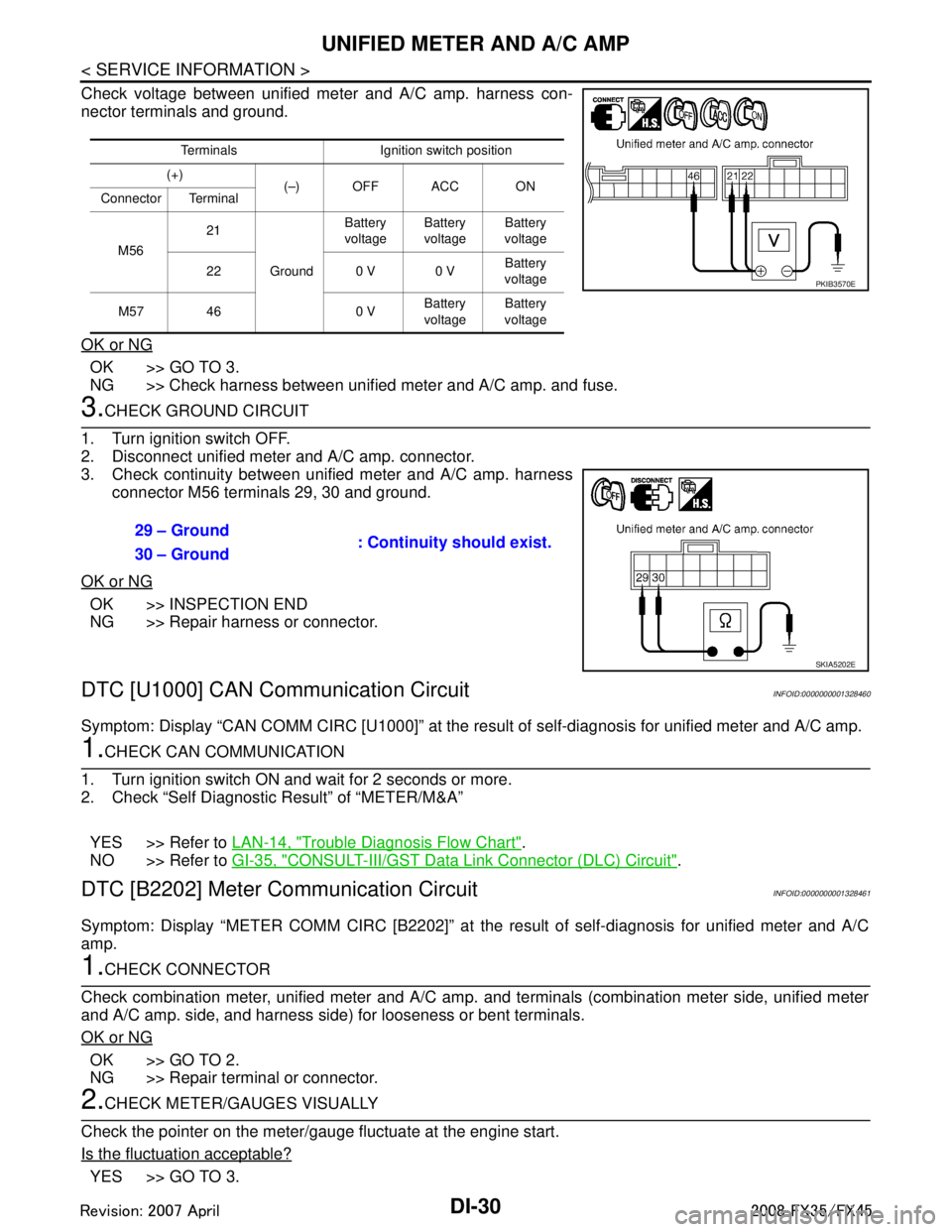
Check voltage between unified meter and A/C amp. harness con-
nector terminals and ground.
OK or NG
OK >> GO TO 3.
NG >> Check harness between unified meter and A/C amp. and fuse.
3.CHECK GROUND CIRCUIT
1. Turn ignition switch OFF.
2. Disconnect unified meter and A/C amp. connector.
3. Check continuity between unified meter and A/C amp. harness connector M56 terminals 29, 30 and ground.
OK or NG
OK >> INSPECTION END
NG >> Repair harness or connector.
DTC [U1000] CAN Communication CircuitINFOID:0000000001328460
Symptom: Display “CAN COMM CIRC [U1000]” at the re sult of self-diagnosis for unified meter and A/C amp.
1.CHECK CAN COMMUNICATION
1. Turn ignition switch ON and wait for 2 seconds or more.
2. Check “Self Diagnostic Result” of “METER/M&A”
YES >> Refer to LAN-14, "
Trouble Diagnosis Flow Chart".
NO >> Refer to GI-35, "
CONSULT-III/GST Data Link Connector (DLC) Circuit".
DTC [B2202] Meter Communication CircuitINFOID:0000000001328461
Symptom: Display “METER COMM CI RC [B2202]” at the result of self-diagnosis for unified meter and A/C
amp.
1.CHECK CONNECTOR
Check combination meter, unified meter and A/C amp. and terminals (combination meter side, unified meter
and A/C amp. side, and harness side) for looseness or bent terminals.
OK or NG
OK >> GO TO 2.
NG >> Repair terminal or connector.
2.CHECK METER/GAUGES VISUALLY
Check the pointer on the meter/gauge fluctuate at the engine start.
Is the fluctuation acceptable?
YES >> GO TO 3.
Terminals Ignition switch position
(+) (–) OFF ACC ON
Connector Terminal
M56 21
Ground Battery
voltage Battery
voltage Battery
voltage
22 0 V 0 V Battery
voltage
M57 46 0 V Battery
voltage Battery
voltage
PKIB3570E
29 – Ground : Continuity should exist.
30 – Ground
SKIA5202E
3AA93ABC3ACD3AC03ACA3AC03AC63AC53A913A773A893A873A873A8E3A773A983AC73AC93AC03AC3
3A893A873A873A8F3A773A9D3AAF3A8A3A8C3A863A9D3AAF3A8B3A8C
Page 1177 of 3924
WARNING CHIMEDI-51
< SERVICE INFORMATION >
C
DE
F
G H
I
J
L
M A
B
DI
N
O P
WARNING CHIME
System DescriptionINFOID:0000000001328473
Buzzer for warning chime system is installed in the combination meter.
The buzzer sounds when the combination meter receives buzzer output signal from each unit through uni- fied meter and A/C amp.
POWER SUPPLY AND CIRCUIT
Power is supplied at all times
through 50A fusible link (letter M, located in the fuse and fusible link block)
to BCM terminal 55,
through 15A fuse [No. 22, located in the fuse block (J/B)]
to key switch and ignition knob switch terminal 3 (with Intelligent Key), and
to key switch terminal 2 (without Intelligent Key), and
to BCM terminal 42,
through 10A fuse [No. 38, located in the fuse and fusible link block (with Intelligent Key)]
to key switch and ignition knob switch terminal 1,
through 10A fuse [No. 19, located in the fuse block (J/B)]
to unified meter and A/C amp. terminal 21, and
to combination meter terminal 8.
When ignition switch is in ON or START position, power is supplied
through 15A fuse [No. 1, located in the fuse block (J/B)]
to BCM terminal 38,
through 10A fuse [No. 12, located in the fuse block (J/B)]
to unified meter and A/C amp. terminal 22,
through 10A fuse [No. 14, located in the fuse block (J/B)]
to combination meter terminal 7.
Ground is supplied
to BCM terminals 49 and 52,
to unified meter and A/C amp. terminals 29 and 30, and
to combination meter terminals 5, 6 and 15
through grounds M35, M45 and M85.
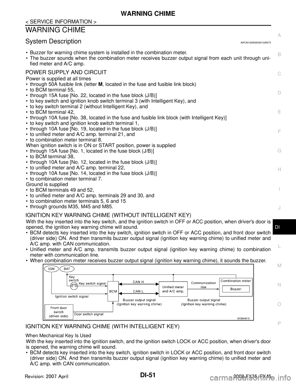
IGNITION KEY WARNING CHIME (WITHOUT INTELLIGENT KEY)
With the key inserted into the key switch, and the igniti on switch in OFF or ACC position, when driver's door is
opened, the ignition key warning chime will sound.
BCM detects key inserted into the key switch, igniti on switch in OFF or ACC position, and front door switch
(driver side) ON. And then transmits buzzer output signal (ignition key warning chime) to unified meter and
A/C amp. with CAN communication.
Unified meter and A/C amp. transmits buzzer output signal (ignition key warning chime) to combination
meter with communication line.
When combination meter receives buzzer output signal (ignition key warning chime), it sounds the buzzer.
IGNITION KEY WARNING CHIME (WITH INTELLIGENT KEY)
When Mechanical Key Is Used
With the key inserted into the ignition switch, and the i gnition switch LOCK or ACC position, when driver's door
is opened, the warning chime will sound.
BCM detects key inserted into the key switch, ignition switch in LOCK or ACC position, and front door switch
(driver side) ON. And then transmits buzzer output signal (ignition key warning chime) to unified meter and
A/C amp. with CAN communication.
SKIB6481E
3AA93ABC3ACD3AC03ACA3AC03AC63AC53A913A773A893A873A873A8E3A773A983AC73AC93AC03AC3
3A893A873A873A8F3A773A9D3AAF3A8A3A8C3A863A9D3AAF3A8B3A8C
Page 1187 of 3924
![INFINITI FX35 2008 Service Manual
WARNING CHIMEDI-61
< SERVICE INFORMATION >
C
DE
F
G H
I
J
L
M A
B
DI
N
O P
If “CAN communication [U1000]” is indicated, after prin ting the monitor item, go to “LAN system”. Refer to
LAN-43, INFINITI FX35 2008 Service Manual
WARNING CHIMEDI-61
< SERVICE INFORMATION >
C
DE
F
G H
I
J
L
M A
B
DI
N
O P
If “CAN communication [U1000]” is indicated, after prin ting the monitor item, go to “LAN system”. Refer to
LAN-43,](/manual-img/42/57017/w960_57017-1186.png)
WARNING CHIMEDI-61
< SERVICE INFORMATION >
C
DE
F
G H
I
J
L
M A
B
DI
N
O P
If “CAN communication [U1000]” is indicated, after prin ting the monitor item, go to “LAN system”. Refer to
LAN-43, "
CAN System Specification Chart".
Trouble DiagnosisINFOID:0000000001328482
HOW TO PERFORM TROUBLE DIAGNOSIS
1. Confirm the symptom or customer complaint.
2. Understand operation description and function description. Refer to DI-51, "
System Description".
3. Perform the preliminary inspection. Refer to "PRELIMINARY INSPECTION".
4. Referring to trouble diagnosis chart, make sure the cause of the malfunction and repair or replace applica-
ble parts. Refer to DI-61, "
Symptom Chart".
5. Does the warning chime operate normally? If so, GO TO 6. If not, GO TO 3.
6. INSPECTION END
PRELIMINARY INSPECTION
1.CHECK BCM (CONSULT-III)
Perform self-diagnosis of BCM. Refer to DI-60, "
CONSULT-III Function (BCM)".
Self
-diagnosis results
No malfunction detected >> GO TO 2.
Malfunction detected >> Check applicable parts, and repair or replace corresponding parts.
2.CHECK UNIFIED METER AND A/C AMP. (CONSULT-III)
Perform self-diagnosis of unified meter and A/C amp. Refer to DI-27, "
CONSULT-III Function (METER/M&A)".
Self
-diagnosis results
No malfunction detected >> INSPECTION END
Malfunction detected >> Check applicable parts, and repair or replace corresponding parts.
Symptom ChartINFOID:0000000001328483
Power Supply and Ground Circuit InspectionINFOID:0000000001328484
1.CHECK FUSE AND FUSIBLE LINK
Check for blown BCM fuses and fusible link.
Symptom Diagnoses/Service procedure
All warning chimes do not activate. Perform the following inspections.
1.
DI-62, "
Combination Meter Buzzer Circuit Inspection".
2. DI-61, "
Power Supply and Ground Circuit Inspection".
Replace BCM, found normal function in the above inspections.
Ignition key
warning chime
does not acti-
vate. Without Intelligent Key.
Perform the following inspections.
1.
DI-63, "
Front Door Switch (Drive r Side) Signal Inspection".
2. DI-64, "
Key Switch Signal Inspection (Without Intelligent Key)".
Replace BCM, found normal function in the above inspections.
With Intelligent Key, when mechan-
ical key is used. Perform the following inspections.
1.
DI-63, "
Front Door Switch (Drive r Side) Signal Inspection".
2. DI-65, "
Key Switch and Ignition Knob Switch Signal Inspection (With In-
telligent Key, When Mechanical Key Is Used)".
Replace BCM, found normal function in the above inspections.
With Intelligent Key, when Intelli-
gent Key is carried with the driver. Refer to
BL-106, "
Trouble Diagnosis Symptom Chart".
Light warning chime does not activate. Perform the following inspections.
1.
DI-63, "
Front Door Switch (Drive r Side) Signal Inspection".
2. LT- 1 0 4 , "
Combination Switch Inspection".
Replace BCM, found normal function in the above inspections.
Seat belt warning chime does not activate. Perform
DI-66, "
Seat Belt Buckle Switch (D river Side) Signal Inspection".
Replace BCM, found normal function in the above inspection.
3AA93ABC3ACD3AC03ACA3AC03AC63AC53A913A773A893A873A873A8E3A773A983AC73AC93AC03AC3
3A893A873A873A8F3A773A9D3AAF3A8A3A8C3A863A9D3AAF3A8B3A8C
Page 1188 of 3924
DI-62
< SERVICE INFORMATION >
WARNING CHIME
OK or NG
OK >> GO TO 2.
NG >> Be sure to eliminate cause of malfunction before installing new fuse or fusible link. Refer to PG-3
.
2.CHECK POWER SUPPLY CIRCUIT
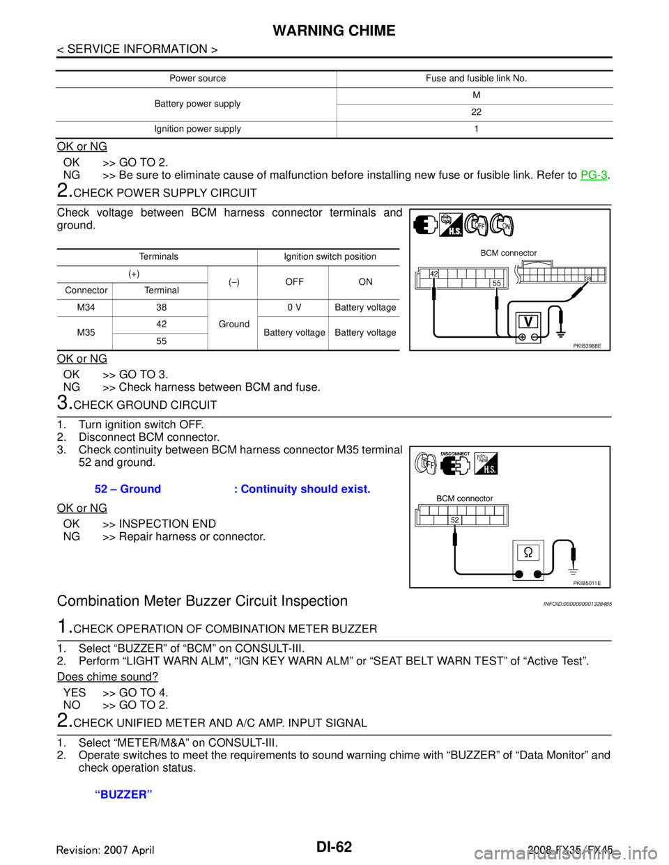
Check voltage between BCM harness connector terminals and
ground.
OK or NG
OK >> GO TO 3.
NG >> Check harness between BCM and fuse.
3.CHECK GROUND CIRCUIT
1. Turn ignition switch OFF.
2. Disconnect BCM connector.
3. Check continuity between BCM harness connector M35 terminal 52 and ground.
OK or NG
OK >> INSPECTION END
NG >> Repair harness or connector.
Combination Meter Buzzer Circuit InspectionINFOID:0000000001328485
1.CHECK OPERATION OF COMBINATION METER BUZZER
1. Select “BUZZER” of “BCM” on CONSULT-III.
2. Perform “LIGHT WARN ALM”, “IGN KEY WARN AL M” or “SEAT BELT WARN TEST” of “Active Test”.
Does chime sound?
YES >> GO TO 4.
NO >> GO TO 2.
2.CHECK UNIFIED METER AND A/C AMP. INPUT SIGNAL
1. Select “METER/M&A” on CONSULT-III.
2. Operate switches to meet the requirements to s ound warning chime with “BUZZER” of “Data Monitor” and
check operation status.
Power source Fuse and fusible link No.
Battery power supply M
22
Ignition power supply 1
Terminals Ignition switch position
(+) (–) OFF ON
Connector Terminal
M34 38 Ground0 V Battery voltage
M35 42
Battery voltage Battery voltage
55
PKIB3988E
52 – Ground : Continui ty should exist.
PKIB5011E
“BUZZER”
3AA93ABC3ACD3AC03ACA3AC03AC63AC53A913A773A893A873A873A8E3A773A983AC73AC93AC03AC3
3A893A873A873A8F3A773A9D3AAF3A8A3A8C3A863A9D3AAF3A8B3A8C
Page 1189 of 3924

WARNING CHIMEDI-63
< SERVICE INFORMATION >
C
DE
F
G H
I
J
L
M A
B
DI
N
O P
OK or NG
OK >> GO TO 3.
NG >> Replace BCM. Refer to BCS-13, "
Removal and Installation of BCM".
3.CHECK BATTERY POWER SUPPLY CIRCUIT OF COMBINATION METER
Check battery power supply circuit of combination meter. Refer to DI-16, "
Power Supply and Ground Circuit
Inspection".
OK or NG
OK >> Replace combination meter.
NG >> Check harness between combination meter and fuse.
4.CHECK BATTERY POWER SUPPLY CIRCUI T OF UNIFIED METER AND A/C AMP.
Check battery power supply circuit of unified meter and A/C amp. Refer to DI-29, "
Power Supply and Ground
Circuit Inspection".
OK or NG
OK >> INSPECTION END
NG >> Check harness between unified meter and A/C amp. and fuse.
Front Door Switch (Drive r Side) Signal InspectionINFOID:0000000001328486
1.CHECK BCM INPUT SIGNAL
With CONSULT-III
1. Select “BCM” on consult-III.
2. With “Data Monitor” of “BUZZER”, confirm “D OOR SW-DR” when the driver side door is operated.
Without CONSULT-III
Check voltage between BCM harness connector B14 terminal 62 and ground.
OK or NG
OK >> INSPECTION END
NG >> GO TO 2.
2.CHECK FRONT DOOR SWIT CH (DRIVER SIDE) CIRCUIT
1. Turn ignition switch OFF.
2. Disconnect BCM connector and front door switch (driver side) connector. When meeting the requirements
to sound warning chime
: On
Except above : Off
“DOOR SW-DR”
When driver side door is opened : On
When driver side door is closed : Off
62 – Ground
When driver side door is opened : Approx. 0 V
When driver side door is closed : Approx. 12 V
3AA93ABC3ACD3AC03ACA3AC03AC63AC53A913A773A893A873A873A8E3A773A983AC73AC93AC03AC3
3A893A873A873A8F3A773A9D3AAF3A8A3A8C3A863A9D3AAF3A8B3A8C
Page 1191 of 3924
WARNING CHIMEDI-65
< SERVICE INFORMATION >
C
DE
F
G H
I
J
L
M A
B
DI
N
O P
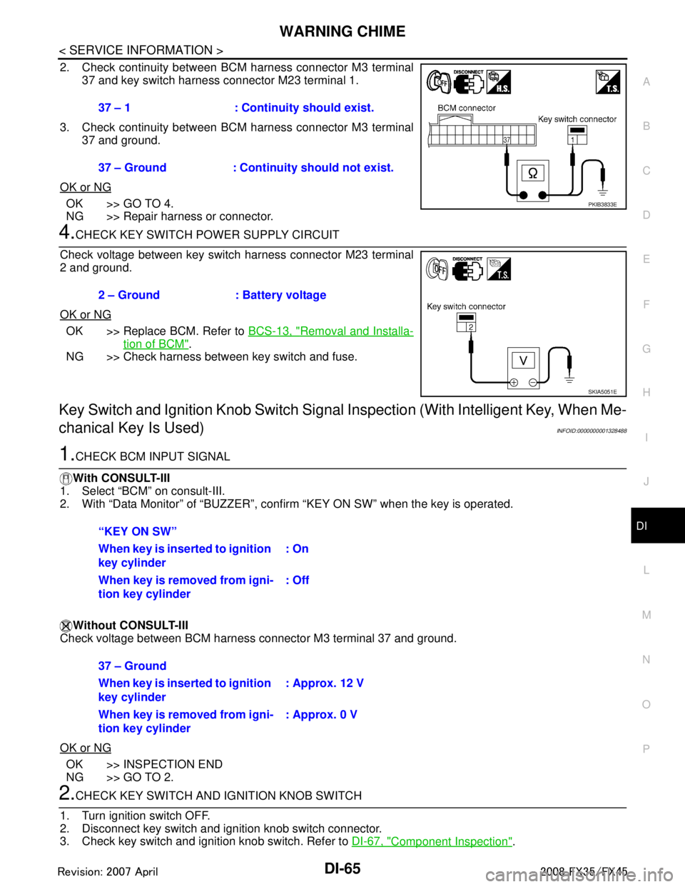
2. Check continuity between BCM harness connector M3 terminal 37 and key switch harness connector M23 terminal 1.
3. Check continuity between BCM harness connector M3 terminal 37 and ground.
OK or NG
OK >> GO TO 4.
NG >> Repair harness or connector.
4.CHECK KEY SWITCH POWER SUPPLY CIRCUIT
Check voltage between key switch harness connector M23 terminal
2 and ground.
OK or NG
OK >> Replace BCM. Refer to BCS-13, "Removal and Installa-
tion of BCM".
NG >> Check harness between key switch and fuse.
Key Switch and Ignition Knob Switch Signal Inspection (With Intelligent Key, When Me-
chanical Key Is Used)
INFOID:0000000001328488
1.CHECK BCM INPUT SIGNAL
With CONSULT-III
1. Select “BCM” on consult-III.
2. With “Data Monitor” of “BUZZER”, conf irm “KEY ON SW” when the key is operated.
Without CONSULT-III
Check voltage between BCM harness connector M3 terminal 37 and ground.
OK or NG
OK >> INSPECTION END
NG >> GO TO 2.
2.CHECK KEY SWITCH AND IG NITION KNOB SWITCH
1. Turn ignition switch OFF.
2. Disconnect key switch and i gnition knob switch connector.
3. Check key switch and ignition knob switch. Refer to DI-67, "
Component Inspection".
37 – 1 : Continuity should exist.
37 – Ground : Continuity should not exist.
PKIB3833E
2 – Ground : Battery voltage
SKIA5051E
“KEY ON SW”
When key is inserted to ignition
key cylinder
: On
When key is removed from igni-
tion key cylinder : Off
37 – Ground
When key is inserted to ignition
key cylinder: Approx. 12 V
When key is removed from igni-
tion key cylinder : Approx. 0 V
3AA93ABC3ACD3AC03ACA3AC03AC63AC53A913A773A893A873A873A8E3A773A983AC73AC93AC03AC3
3A893A873A873A8F3A773A9D3AAF3A8A3A8C3A863A9D3AAF3A8B3A8C