2008 INFINITI FX35 display
[x] Cancel search: displayPage 3891 of 3924

WW-16
< SERVICE INFORMATION >
FRONT WIPER AND WASHER SYSTEM
NOTE:
This item is displayed, but cannot be monitored.
ACTIVE TEST
Display Item List
CONSULT-III Functions (IPDM E/R)INFOID:0000000001328553
CONSULT-III can display each diagnostic item using the diagnostic test mode shown following.
DATA MONITOR
All Signals, Main Signals, Selection From Menu
NOTE:
Perform monitoring of IPDM E/R data with ignition switch ON. When ignition switch is at ACC, the display may
not be correct.
ACTIVE TEST
FR WIPER INT “ON/OFF” Displays status (front wiper switch intermittent position: ON/other: OFF) of front wiper intermit-
tent switch judged from the front wiper switch signal.
FR WASHER SW “ON/OFF” Displays status (front washer switch ON posi
tion: ON/other: OFF) of front washer switch
judged from the front wiper switch signal.
INT VOLUME “1 - 7” Displays status (wiper intermittent dial position setting 1- 7) of intermittent volume switch
judged from the front wiper switch signal.
FR WIPER STOP “ON/OFF” Displays status (front wiper stop position: ON/move: OFF) of front wiper motor stop judged
from the front wiper auto stop signal.
VEHICLE SPEED “km/h” Displays st atus vehicle speed as judged from vehicle speed signal.
RR WIPER ON “OFF” Displays status (rear wiper switch ON position
: ON/other: OFF) of rear wiper switch judged
from the rear wiper switch signal.
RR WIPER INT “OFF” Displays status (rear wiper switch intermittent position: ON/other: OFF) of rear wiper intermit-
tent switch judged from the rear wiper switch signal.
RR WASHER SW “OFF” Displays status (rear washer switch ON position: ON/other: OFF) of rear washer switch judged
from the rear wiper switch signal.
RR WIPER STOP “OFF” Displays status (rear wiper stop position: OFF/move: ON) of rear wiper motor stop judged from
the rear wiper auto stop signal.
H/L WASH SW
NOTE“ON/OFF” —
Monitor item Contents
Test item Display on CONSULT-III screen Description
Front wiper output FR WIPER With a certain operation (OFF, HI, LO, INT), front wiper can be operated. Rear wiper output RR WIPER Rear wiper can be operated by any ON-OFF operation
Diagnosis Mode Description
SELF-DIAG RESULTS Refer to PG-18, "
CONSULT-III Function (IPDM E/R)".
DATA MONITOR The input/output data of IPDM E/R is displayed in real time.
CAN DIAG SUPPORT MNTR The result of transmit/receive diagnosis of CAN communication can be read.
ACTIVE TEST IPDM E/R sends a drive signal to electronic components to check their operation.
Item name CONSULT-III
screen display Display or unit Monitor item selection
Description
ALL
SIGNALS MAIN
SIGNALS SELECTION
FROM MENU
FR wiper request FR WIP REQ STOP/LOW/HI ×× ×Signal status input from BCM
Wiper auto stop WIP AUTO STOP ACT P/STOP P ×× ×Output status of IPDM E/R
Wiper protection WIP PROT OFF/BLOCK ×× ×Control status of IPDM E/R
3AA93ABC3ACD3AC03ACA3AC03AC63AC53A913A773A893A873A873A8E3A773A983AC73AC93AC03AC3
3A893A873A873A8F3A773A9D3AAF3A8A3A8C3A863A9D3AAF3A8B3A8C
Page 3892 of 3924
FRONT WIPER AND WASHER SYSTEMWW-17
< SERVICE INFORMATION >
C
DE
F
G H
I
J
L
M A
B
WW
N
O P
Front Wiper Does Not OperateINFOID:0000000001328554
CAUTION:
During IPDM E/R fail-safe control, fr ont wipers may not operate. Refer to PG-17, "
System Description"
in “PG IPDM E/R” to make sure that it is not in fail-safe status.
1.ACTIVE TEST
With CONSULT-III
1. Select “FRONT WIPER” of IPDM E/R active test item.
2. With operating the test item, check that front wiper “LO” and “HI” operation.
Without CONSULT-III
Start up auto active test. Refer to PG-20, "
Auto Active Test".
Does front wiper operate normally?
YES >> GO TO 5.
NO >> GO TO 2.
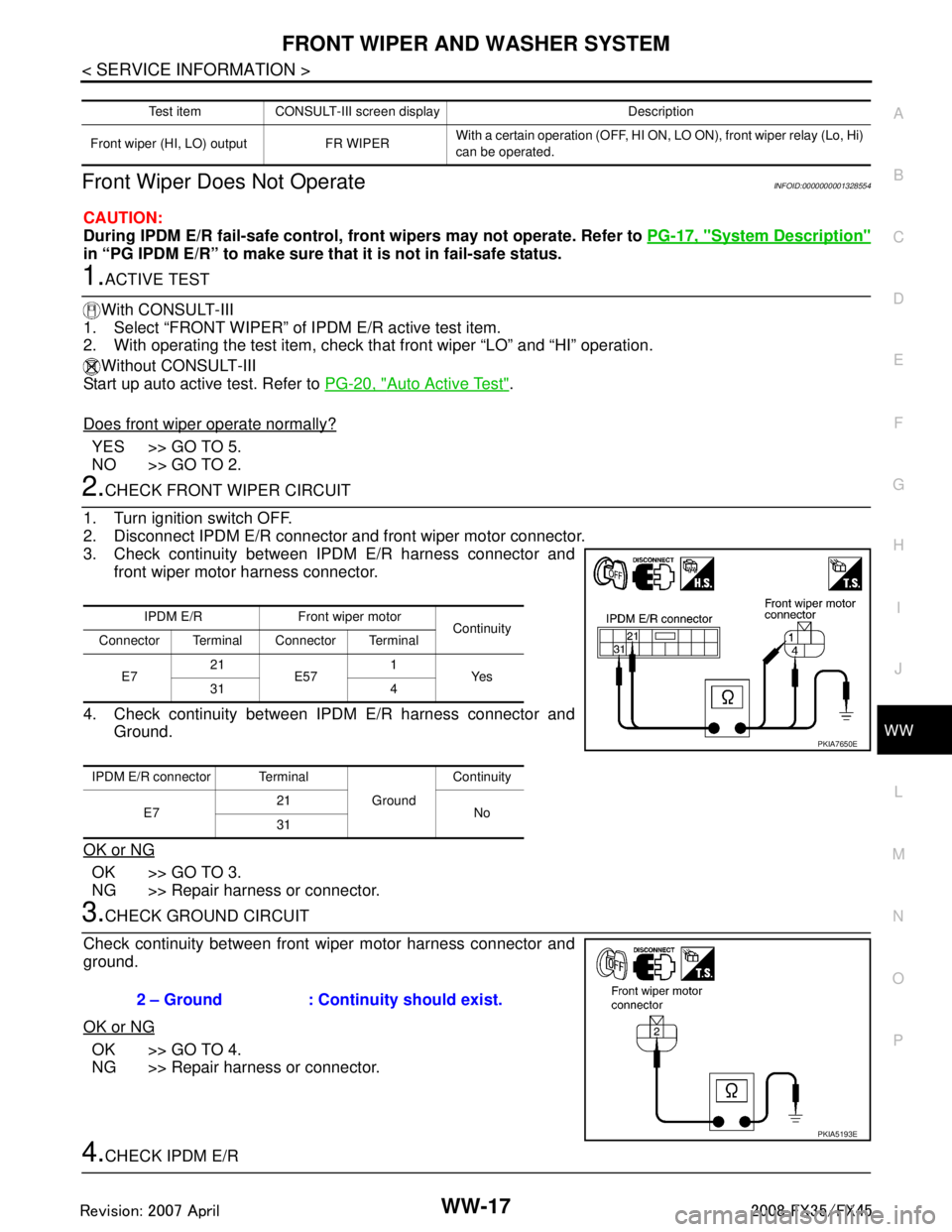
2.CHECK FRONT WIPER CIRCUIT
1. Turn ignition switch OFF.
2. Disconnect IPDM E/R connector and front wiper motor connector.
3. Check continuity between IPDM E/R harness connector and front wiper motor harness connector.
4. Check continuity between IPDM E/R harness connector and Ground.
OK or NG
OK >> GO TO 3.
NG >> Repair harness or connector.
3.CHECK GROUND CIRCUIT
Check continuity between front wiper motor harness connector and
ground.
OK or NG
OK >> GO TO 4.
NG >> Repair harness or connector.
4.CHECK IPDM E/R
Test item CONSULT-III screen display Description
Front wiper (HI, LO) output FR WIPER With a certain operation (OFF, HI ON,
LO ON), front wiper relay (Lo, Hi)
can be operated.
IPDM E/R Front wiper motor Continuity
Connector Terminal Connector Terminal
E7 21
E57 1
Ye s
31 4
IPDM E/R connector Terminal GroundContinuity
E7 21
No
31
PKIA7650E
2 – Ground : Continuity should exist.
PKIA5193E
3AA93ABC3ACD3AC03ACA3AC03AC63AC53A913A773A893A873A873A8E3A773A983AC73AC93AC03AC3
3A893A873A873A8F3A773A9D3AAF3A8A3A8C3A863A9D3AAF3A8B3A8C
Page 3893 of 3924
WW-18
< SERVICE INFORMATION >
FRONT WIPER AND WASHER SYSTEM
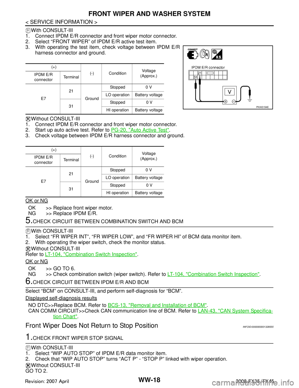
With CONSULT-III
1. Connect IPDM E/R connector and front wiper motor connector.
2. Select “FRONT WIPER” of IPDM E/R active test item.
3. With operating the test item , check voltage between IPDM E/R
harness connector and ground.
Without CONSULT-III
1. Connect IPDM E/R connector and front wiper motor connector.
2. Start up auto active test. Refer to PG-20, "
Auto Active Test".
3. Check voltage between IPDM E/R harness connector and ground.
OK or NG
OK >> Replace front wiper motor.
NG >> Replace IPDM E/R.
5.CHECK CIRCUIT BETWEEN COMB INATION SWITCH AND BCM
With CONSULT-III
1. Select “FR WIPER INT”, “FR WIPER LOW”, and “FR WIPER HI” of BCM data monitor item.
2. With operating the wiper switch, check the monitor status.
Without CONSULT-III
Refer to LT-104, "
Combination Switch Inspection".
OK or NG
OK >> GO TO 6.
NG >> Check combination switch (wiper switch). Refer to LT-104, "
Combination Switch Inspection".
6.CHECK CIRCUIT BETWEEN IPDM E/R AND BCM
Select “BCM” on CONSULT-III, and perform self-diagnosis for “BCM”.
Displayed self
-diagnosis results
NO DTC>>Replace BCM. Refer to BCS-13, "Removal and Installation of BCM".
CAN COMM CIRCUIT>>Check CAN communi cation line of BCM. Refer to LAN-43, "
CAN System Specifica-
tion Chart".
Front Wiper Does Not Return to Stop PositionINFOID:0000000001328555
1.CHECK FRONT WIPER STOP SIGNAL
With CONSULT-III
1. Select “WIP AUTO STOP” of IPDM E/R data monitor item.
2. Check that “WIP AUTO STOP” turns “ACT P” - “STOP P” linked with wiper operation.
Without CONSULT-III
GO TO 2.
(+)
(-) Condition Vol tag e
(Approx.)
IPDM E/R
connector Te r m i n a l
E7 21
Ground Stopped 0 V
LO operation Battery voltage
31 Stopped 0 V
HI operation Battery voltage
(+) (-) Condition Vol tag e
(Approx.)
IPDM E/R
connector Te r m i n a l
E7 21
Ground Stopped 0 V
LO operation Battery voltage
31 Stopped 0 V
HI operation Battery voltage
PKIA5194E
3AA93ABC3ACD3AC03ACA3AC03AC63AC53A913A773A893A873A873A8E3A773A983AC73AC93AC03AC3
3A893A873A873A8F3A773A9D3AAF3A8A3A8C3A863A9D3AAF3A8B3A8C
Page 3897 of 3924
WW-22
< SERVICE INFORMATION >
FRONT WIPER AND WASHER SYSTEM
Displayed self-diagnosis results
NO DTC>>Replace BCM. Refer to BCS-13, "Removal and Installation of BCM".
CAN COMM CIRCUIT>>Check CAN communi cation line of BCM. Refer to LAN-43, "
CAN System Specifica-
tion Chart".
Front Wiper Intermittent Operation S witch Position Cannot Be AdjustedINFOID:0000000001328560
1.CHECK CIRCUIT BETWEEN COMB INATION SWITCH AND BCM
With CONSULT-III
1. Select “INT VOLUME” of BCM data monitor item.
2. Check that “INT VOLUME”, changes in order fo rm 1 to 7 according to wiper switch operation.
Without CONSULT-III
Refer to LT-104, "
Combination Switch Inspection".
OK or NG
OK >> Replace BCM. Refer to BCS-13, "Removal and Installation of BCM".
NG >> Check combination switch (wiper switch). Refer to LT-104, "
Combination Switch Inspection".
Wiper Does Not Wipe When Front Washer OperatesINFOID:0000000001328561
1.CHECK CIRCUIT BETWEEN COMB INATION SWITCH AND BCM
With CONSULT-III
1. Select “FR WASHER SW” of BCM data monitor item.
2. Check that “FR WASHER SW” turn ON-OFF according to front wiper switch operation.
Without CONSULT-III
Refer to LT-104, "
Combination Switch Inspection".
OK or NG
OK >> Replace BCM Refer to BCS-13, "Removal and Installation of BCM".
NG >> Check combination switch (wiper switch). Refer to LT-104, "
Combination Switch Inspection".
After Front Wiper Operate for 10 Seconds, They Stop for 20 Seconds, and After Re-
peating the Operation Five Time s, They Become Inoperative
INFOID:0000000001328562
CAUTION:
When auto-stop signal has not varied for 10 seconds or longer while IPDM E/R is operating front wip-
ers, IPDM E/R considers that front wipers are locked, and stops wiper output. That causes this symp-
tom.
This status can be checked by “DATA MONITOR” of “IPDM E/R” on which “WIPER PROTECTION”
item shows “BLOCK”.
1.CHECK WIPER MOTOR SIGNAL
With CONSULT-III
1. Select “WIP AUTO STOP” of BCM data monitor item.
2. Check that “WIP AUTO STOP” turns “ACT P” - “STOP P” linked with wiper operation.
Without CONSULT-III
GO TO 2.
OK or NG
OK >> Replace IPDM E/R.
NG >> GO TO 2.
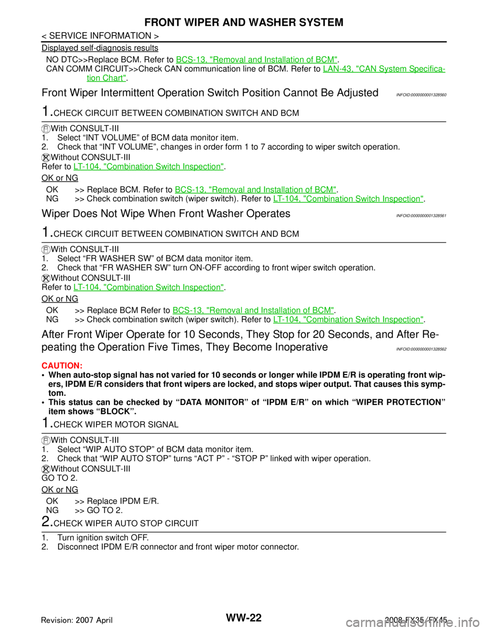
2.CHECK WIPER AUTO STOP CIRCUIT
1. Turn ignition switch OFF.
2. Disconnect IPDM E/R connector and front wiper motor connector.
3AA93ABC3ACD3AC03ACA3AC03AC63AC53A913A773A893A873A873A8E3A773A983AC73AC93AC03AC3
3A893A873A873A8F3A773A9D3AAF3A8A3A8C3A863A9D3AAF3A8B3A8C
Page 3911 of 3924
WW-36
< SERVICE INFORMATION >
REAR WIPER AND WASHER SYSTEM
2. Understand operation description and function description. Refer to WW-30, "System Description".
3. Perform the Preliminary Check. Refer to WW-36, "
Preliminary Check".
4. Check symptom and repair or r eplace the cause of malfunction.
5. Does the rear wiper and washer operate no rmally? If YES, GO TO 6. If NO, GO TO 4.
6. INSPECTION END
Preliminary CheckINFOID:0000000001328581
CHECK POWER SUPPLY AND GROUND CIRCUIT
1.CHECK FUSES
Check for blown fuses.
Refer to WW-32, "Wiring Diagram - WIP/ R -".
OK or NG
OK >> GO TO 2.
NG >> If fuse is blown, be sure to eliminate caus e of malfunction before installing new fuse, Refer to PG-
3, "Schematic".
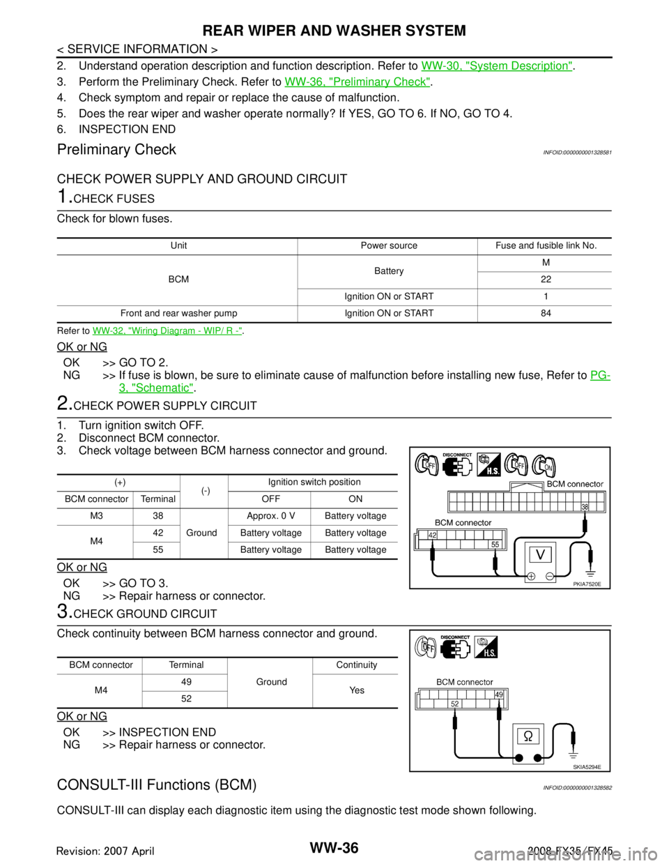
2.CHECK POWER SUPPLY CIRCUIT
1. Turn ignition switch OFF.
2. Disconnect BCM connector.
3. Check voltage between BCM harness connector and ground.
OK or NG
OK >> GO TO 3.
NG >> Repair harness or connector.
3.CHECK GROUND CIRCUIT
Check continuity between BCM harness connector and ground.
OK or NG
OK >> INSPECTION END
NG >> Repair harness or connector.
CONSULT-III Functions (BCM)INFOID:0000000001328582
CONSULT-III can display each diagnostic item using the diagnostic test mode shown following.
Unit Power source Fuse and fusible link No.
BCM BatteryM
22
Ignition ON or START 1
Front and rear washer pump Ignition ON or START 84
(+) (-)Ignition switch position
BCM connector Terminal OFF ON M3 38 GroundApprox. 0 V Battery voltage
M4 42 Battery voltage Battery voltage
55 Battery voltage Battery voltage
PKIA7520E
BCM connector Terminal
GroundContinuity
M4 49
Ye s
52
SKIA5294E
3AA93ABC3ACD3AC03ACA3AC03AC63AC53A913A773A893A873A873A8E3A773A983AC73AC93AC03AC3
3A893A873A873A8F3A773A9D3AAF3A8A3A8C3A863A9D3AAF3A8B3A8C
Page 3912 of 3924
REAR WIPER AND WASHER SYSTEMWW-37
< SERVICE INFORMATION >
C
DE
F
G H
I
J
L
M A
B
WW
N
O P
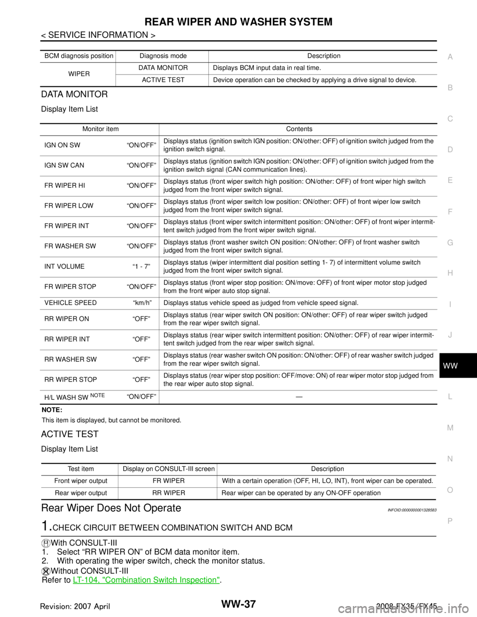
DATA MONITOR
Display Item List
NOTE:
This item is displayed, but cannot be monitored.
ACTIVE TEST
Display Item List
Rear Wiper Does Not OperateINFOID:0000000001328583
1.CHECK CIRCUIT BETWEEN COMB INATION SWITCH AND BCM
With CONSULT-III
1. Select “RR WIPER ON” of BCM data monitor item.
2. With operating the wiper switch, check the monitor status.
Without CONSULT-III
Refer to LT-104, "
Combination Switch Inspection".
BCM diagnosis position Diagnosis mode Description
WIPER DATA MONITOR Displays BCM input data in real time.
ACTIVE TEST Device operation can be checked by applying a drive signal to device.
Monitor item Contents
IGN ON SW “ON/OFF” Displays status (ignition switch IGN position: ON/other: OFF) of ignition switch judged from the
ignition switch signal.
IGN SW CAN “ON/OFF” Displays status (ignition switch IGN position: ON/other: OFF) of ignition switch judged from the
ignition switch signal (CAN communication lines).
FR WIPER HI “ON/OFF” Displays status (front wiper switch high position: ON/other: OFF) of front wiper high switch
judged from the front wiper switch signal.
FR WIPER LOW “ON/OFF” Displays status (front wiper switch low position: ON/other: OFF) of front wiper low switch
judged from the front wiper switch signal.
FR WIPER INT “ON/OFF” Displays status (front wiper switch intermittent
position: ON/other: OFF) of front wiper intermit-
tent switch judged from the front wiper switch signal.
FR WASHER SW “ON/OFF” Displays status (front washer switch ON position: ON/other: OFF) of front washer switch
judged from the front wiper switch signal.
INT VOLUME “1 - 7” Displays status (wiper intermittent dial position setting 1- 7) of intermittent volume switch
judged from the front wiper switch signal.
FR WIPER STOP “ON/OFF” Displays status (front wiper stop position: ON/move: OFF) of front wiper motor stop judged
from the front wiper auto stop signal.
VEHICLE SPEED “km/h” Displays status vehicle sp eed as judged from vehicle speed signal.
RR WIPER ON “OFF” Displays status (rear wiper switch ON position: ON/other: OFF) of rear wiper switch judged
from the rear wiper switch signal.
RR WIPER INT “OFF” Displays status (rear wiper switch intermittent position: ON/other: OFF) of rear wiper intermit-
tent switch judged from the rear wiper switch signal.
RR WASHER SW “OFF” Displays status (rear washer switch ON position: ON/other: OFF) of rear washer switch judged
from the rear wiper switch signal.
RR WIPER STOP “OFF” Displays status (rear wiper stop position: OFF/move: ON) of rear wiper motor stop judged from
the rear wiper auto stop signal.
H/L WASH SW
NOTE“ON/OFF” —
Test item Display on CONSULT-III screen Description
Front wiper output FR WIPER With a certain operation (OFF, HI, LO, INT), front wiper can be operated. Rear wiper output RR WIPER Rear wiper can be operated by any ON-OFF operation
3AA93ABC3ACD3AC03ACA3AC03AC63AC53A913A773A893A873A873A8E3A773A983AC73AC93AC03AC3
3A893A873A873A8F3A773A9D3AAF3A8A3A8C3A863A9D3AAF3A8B3A8C