2008 INFINITI FX35 display
[x] Cancel search: displayPage 3852 of 3924
WT-12
< SERVICE INFORMATION >
TIRE PRESSURE MONITORING SYSTEM
Note 1: Standard air pressure is for 220 kpa (2.2 kg/cm2, 32 psi) vehicles.
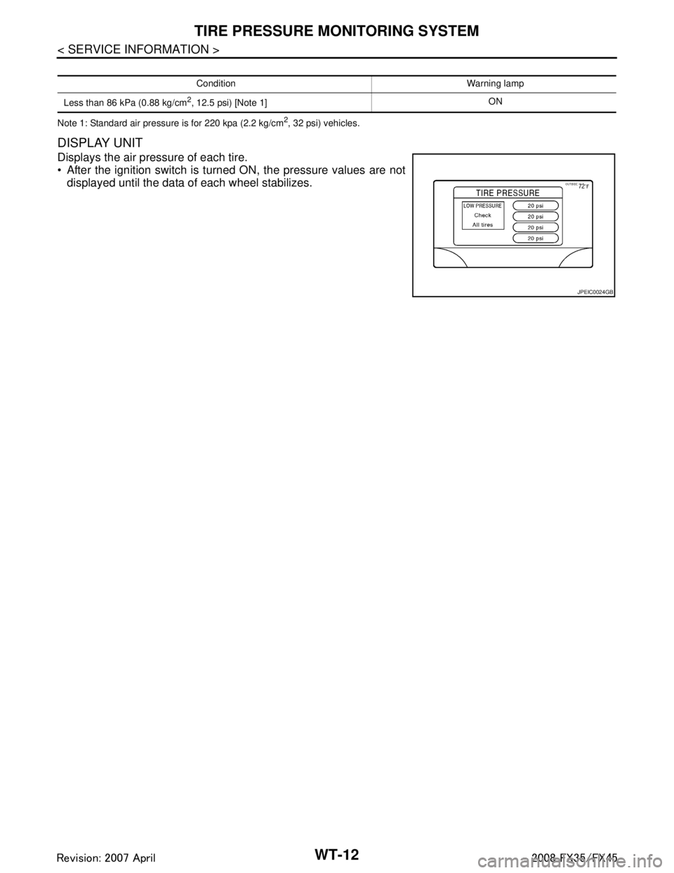
DISPLAY UNIT
Displays the air pressure of each tire.
After the ignition switch is turned ON, the pressure values are notdisplayed until the data of each wheel stabilizes.
Condition Warning lamp
Less than 86 kPa (0.88 kg/cm
2, 12.5 psi) [Note 1] ON
JPEIC0024GB
3AA93ABC3ACD3AC03ACA3AC03AC63AC53A913A773A893A873A873A8E3A773A983AC73AC93AC03AC3
3A893A873A873A8F3A773A9D3AAF3A8A3A8C3A863A9D3AAF3A8B3A8C
Page 3862 of 3924
WT-22
< SERVICE INFORMATION >
TROUBLE DIAGNOSES
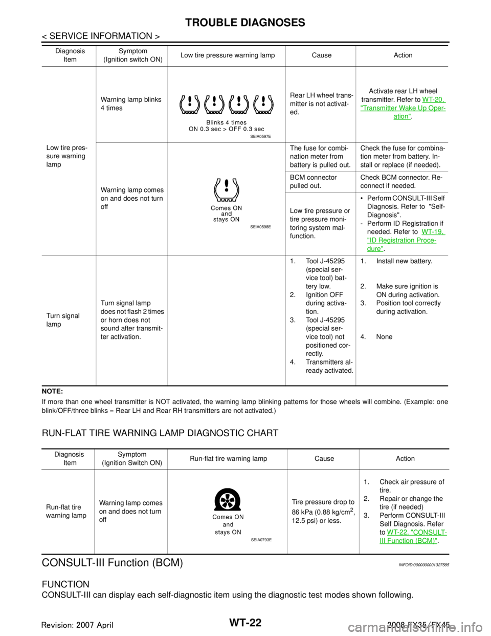
NOTE:
If more than one wheel transmitter is NOT activated, the warning lamp blinking patterns for those wheels will combine. (Example: one
blink/OFF/three blinks = Rear LH and Rear RH transmitters are not activated.)
RUN-FLAT TIRE WARNING LAMP DIAGNOSTIC CHART
CONSULT-III Function (BCM)INFOID:0000000001327585
FUNCTION
CONSULT-III can display each self-diagnostic item using the diagnostic test modes shown following.
Low tire pres-
sure warning
lampWarning lamp blinks
4 times
Rear LH wheel trans-
mitter is not activat-
ed.Activate rear LH wheel
transmitter. Refer to WT-20,
"Transmitter Wake Up Oper-
ation".
Warning lamp comes
on and does not turn
off The fuse for combi-
nation meter from
battery is pulled out.
Check the fuse for combina-
tion meter from battery. In-
stall or replace (if needed).
BCM connector
pulled out. Check BCM connector. Re-
connect if needed.
Low tire pressure or
tire pressure moni-
toring system mal-
function. Perform CONSULT-III Self
Diagnosis. Refer to "Self-
Diagnosis".
- Perform ID Registration if needed. Refer to WT-19,
"ID Registration Proce-
dure".
Turn signal
lamp Turn signal lamp
does not flash 2 times
or horn does not
sound after transmit-
ter activation. 1. Tool J-45295
(special ser-
vice tool) bat-
tery low.
2. Ignition OFF
during activa-
tion.
3. Tool J-45295
(special ser-
vice tool) not
positioned cor-
rectly.
4. Transmitters al- ready activated. 1. Install new battery.
2. Make sure ignition is
ON during activation.
3. Position tool correctly during activation.
4. None
Diagnosis
Item Symptom
(Ignition switch ON) Low tire pressure wa
rning lamp Cause Action
SEIA0597E
SEIA0598E
Diagnosis
Item Symptom
(Ignition Switch ON) Run-flat tire warning lamp Cause Action
Run-flat tire
warning lamp Warning lamp comes
on and does not turn
off Tire pressure drop to
86 kPa (0.88 kg/cm
2,
12.5 psi) or less. 1. Check air pressure of
tire.
2. Repair or change the
tire (if needed)
3. Perform CONSULT-III Self Diagnosis. Refer
to WT-22, "
CONSULT-
III Function (BCM)".SEIA0793E
3AA93ABC3ACD3AC03ACA3AC03AC63AC53A913A773A893A873A873A8E3A773A983AC73AC93AC03AC3
3A893A873A873A8F3A773A9D3AAF3A8A3A8C3A863A9D3AAF3A8B3A8C
Page 3863 of 3924
TROUBLE DIAGNOSESWT-23
< SERVICE INFORMATION >
C
DF
G H
I
J
K L
M A
B
WT
N
O P
WORK SUPPORT MODE
Test Item
ID Read
ID Regist
ID Read
The registered ID number is displayed.
ID Regist
Refer to WT-19, "ID Registration Procedure".
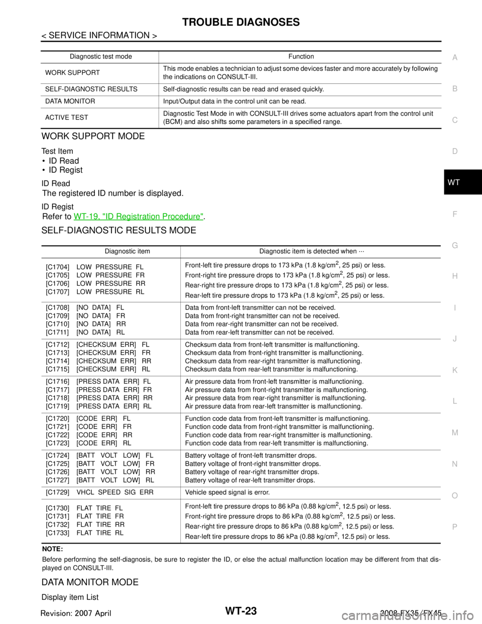
SELF-DIAGNOSTIC RESULTS MODE
NOTE:
Before performing the self-diagnosis, be sure to register the ID, or else the actual malfunction location may be different from that dis-
played on CONSULT-III.
DATA MONITOR MODE
Display item List
Diagnostic test mode Function
WORK SUPPORT This mode enables a technician to adjust some devices faster and more accurately by following
the indications on CONSULT-III.
SELF-DIAGNOSTIC RESULTS Self-diagnostic results can be read and erased quickly.
DATA MONITOR Input/Output data in the control unit can be read.
ACTIVE TEST Diagnostic Test Mode in with CONSULT-III drives some actuators apart from the control unit
(BCM) and also shifts some pa
rameters in a specified range.
Diagnostic item Diagnostic item is detected when ···
[C1704]
[C1705]
[C1706]
[C1707] LOW PRESSURE FL
LOW PRESSURE FR
LOW PRESSURE RR
LOW PRESSURE RL Front-left tire pressure drops to 173 kPa (1.8 kg/cm
2, 25 psi) or less.
Front-right tire pressure drops to 173 kPa (1.8 kg/cm2, 25 psi) or less.
Rear-right tire pressure dr ops to 173 kPa (1.8 kg/cm2, 25 psi) or less.
Rear-left tire pressure drops to 173 kPa (1.8 kg/cm2, 25 psi) or less.
[C1708]
[C1709]
[C1710]
[C1711] [NO DATA] FL
[NO DATA] FR
[NO DATA] RR
[NO DATA] RL Data from front-left transmitter can not be received.
Data from front-right transmitter can not be received.
Data from rear-right transm
itter can not be received.
Data from rear-left transmitter can not be received.
[C1712]
[C1713]
[C1714]
[C1715] [CHECKSUM ERR] FL
[CHECKSUM ERR] FR
[CHECKSUM ERR] RR
[CHECKSUM ERR] RL Checksum data from front-left transmitter is malfunctioning.
Checksum data from front-right transmitter is malfunctioning.
Checksum data from
rear-right transmitter is malfunctioning.
Checksum data from rear-left transmitter is malfunctioning.
[C1716]
[C1717]
[C1718]
[C1719] [PRESS DATA ERR] FL
[PRESS DATA ERR] FR
[PRESS DATA ERR] RR
[PRESS DATA ERR] RL Air pressure data from front-left transmitter is malfunctioning.
Air pressure data from front-right transmitter is malfunctioning.
Air pressure data from
rear-right transmitter is malfunctioning.
Air pressure data from rear-left transmitter is malfunctioning.
[C1720]
[C1721]
[C1722]
[C1723] [CODE ERR] FL
[CODE ERR] FR
[CODE ERR] RR
[CODE ERR] RL Function code data from front-left transmitter is malfunctioning.
Function code data from front-right transmitter is malfunctioning.
Function code data from rear-righ
t transmitter is malfunctioning.
Function code data from rear-left transmitter is malfunctioning.
[C1724]
[C1725]
[C1726]
[C1727] [BATT VOLT LOW] FL
[BATT VOLT LOW] FR
[BATT VOLT LOW] RR
[BATT VOLT LOW] RL Battery voltage of front-left transmitter drops.
Battery voltage of front-right transmitter drops.
Battery voltage of rea
r-right transmitter drops.
Battery voltage of rear-left transmitter drops.
[C1729] VHCL SPEED SIG ERR Veh icle speed signal is error.
[C1730]
[C1731]
[C1732]
[C1733] FLAT TIRE FL
FLAT TIRE FR
FLAT TIRE RR
FLAT TIRE RL Front-left tire pressure drops to 86 kPa (0.88 kg/cm
2, 12.5 psi) or less.
Front-right tire pressure drops to 86 kPa (0.88 kg/cm2, 12.5 psi) or less.
Rear-right tire pressure dr ops to 86 kPa (0.88 kg/cm2, 12.5 psi) or less.
Rear-left tire pressure drops to 86 kPa (0.88 kg/cm2, 12.5 psi) or less.
3AA93ABC3ACD3AC03ACA3AC03AC63AC53A913A773A893A873A873A8E3A773A983AC73AC93AC03AC3
3A893A873A873A8F3A773A9D3AAF3A8A3A8C3A863A9D3AAF3A8B3A8C
Page 3868 of 3924
WT-28
< SERVICE INFORMATION >
TROUBLE DIAGNOSIS FOR SELF-DIAGNOSTIC ITEMS
TROUBLE DIAGNOSIS FOR SELF-DIAGNOSTIC ITEMS
Transmitter or Control Unit (BCM)INFOID:0000000001327589
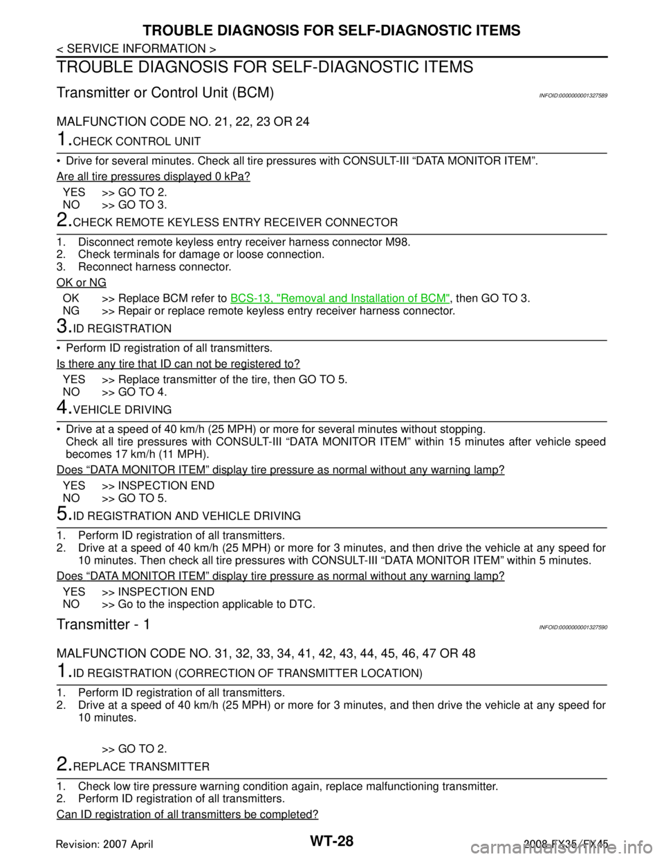
MALFUNCTION CODE NO. 21, 22, 23 OR 24
1.CHECK CONTROL UNIT
Drive for several minutes. Check all tire pr essures with CONSULT-III “DATA MONITOR ITEM”.
Are all tire pressures displayed 0 kPa?
YES >> GO TO 2.
NO >> GO TO 3.
2.CHECK REMOTE KEYLESS EN TRY RECEIVER CONNECTOR
1. Disconnect remote keyless entry receiver harness connector M98.
2. Check terminals for damage or loose connection.
3. Reconnect harness connector.
OK or NG
OK >> Replace BCM refer to BCS-13, "Removal and Installation of BCM", then GO TO 3.
NG >> Repair or replace remote keyless entry receiver harness connector.
3.ID REGISTRATION
Perform ID registration of all transmitters.
Is there any tire that ID can not be registered to?
YES >> Replace transmitter of the tire, then GO TO 5.
NO >> GO TO 4.
4.VEHICLE DRIVING
Drive at a speed of 40 km/h (25 MPH) or more for several minutes without stopping. Check all tire pressures with CONSULT-III “DATA MONITOR ITEM” within 15 minutes after vehicle speed
becomes 17 km/h (11 MPH).
Does
“DATA MONITOR ITEM” display tire pressure as normal without any warning lamp?
YES >> INSPECTION END
NO >> GO TO 5.
5.ID REGISTRATION AND VEHICLE DRIVING
1. Perform ID registration of all transmitters.
2. Drive at a speed of 40 km/h (25 MPH) or more fo r 3 minutes, and then drive the vehicle at any speed for
10 minutes. Then check all tire pressures with CO NSULT-III “DATA MONITOR ITEM” within 5 minutes.
Does
“DATA MONITOR ITEM” display tire pressure as normal without any warning lamp?
YES >> INSPECTION END
NO >> Go to the inspection applicable to DTC.
Transmitter - 1INFOID:0000000001327590
MALFUNCTION CODE NO. 31, 32, 33, 34, 41, 42, 43, 44, 45, 46, 47 OR 48
1.ID REGISTRATION (CORRECTION OF TRANSMITTER LOCATION)
1. Perform ID registration of all transmitters.
2. Drive at a speed of 40 km/h (25 MPH) or more fo r 3 minutes, and then drive the vehicle at any speed for
10 minutes.
>> GO TO 2.
2.REPLACE TRANSMITTER
1. Check low tire pressure warning condition again, replace malfunctioning transmitter.
2. Perform ID registration of all transmitters.
Can ID registration of all transmitters be completed?
3AA93ABC3ACD3AC03ACA3AC03AC63AC53A913A773A893A873A873A8E3A773A983AC73AC93AC03AC3
3A893A873A873A8F3A773A9D3AAF3A8A3A8C3A863A9D3AAF3A8B3A8C
Page 3869 of 3924
TROUBLE DIAGNOSIS FOR SELF-DIAGNOSTIC ITEMS
WT-29
< SERVICE INFORMATION >
C
D F
G H
I
J
K L
M A
B
WT
N
O P
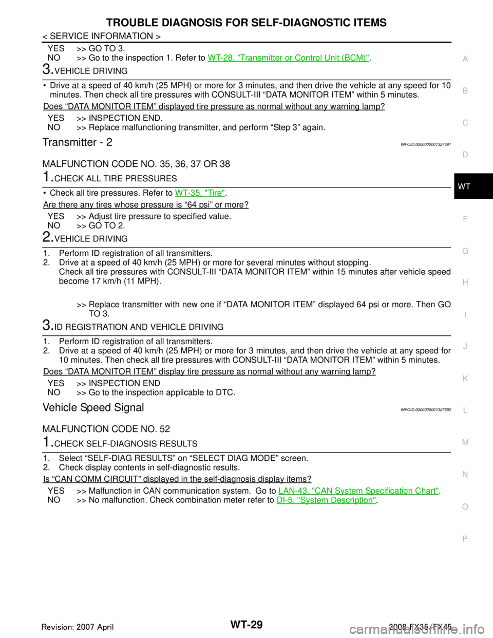
YES >> GO TO 3.
NO >> Go to the inspection 1. Refer to WT-28, "
Transmitter or Control Unit (BCM)".
3.VEHICLE DRIVING
Drive at a speed of 40 km/h (25 MPH) or more for 3 minutes, and then drive the vehicle at any speed for 10
minutes. Then check all tire pressures with CO NSULT-III “DATA MONITOR ITEM” within 5 minutes.
Does
“DATA MONITOR ITEM” displayed tire pressure as normal without any warning lamp?
YES >> INSPECTION END.
NO >> Replace malfunctioning transmitter, and perform “Step 3” again.
Transmitter - 2INFOID:0000000001327591
MALFUNCTION CODE NO. 35, 36, 37 OR 38
1.CHECK ALL TIRE PRESSURES
Check all tire pressures. Refer to WT-35, "
Tire".
Are there any tires whose pressure is
“64 psi” or more?
YES >> Adjust tire pressure to specified value.
NO >> GO TO 2.
2.VEHICLE DRIVING
1. Perform ID registration of all transmitters.
2. Drive at a speed of 40 km/h (25 MPH) or more for several minutes without stopping.
Check all tire pressures with CONSULT-III “DATA MO NITOR ITEM” within 15 minutes after vehicle speed
become 17 km/h (11 MPH).
>> Replace transmitter with new one if “DATA MO NITOR ITEM” displayed 64 psi or more. Then GO
TO 3.
3.ID REGISTRATION AND VEHICLE DRIVING
1. Perform ID registration of all transmitters.
2. Drive at a speed of 40 km/h (25 MPH) or more fo r 3 minutes, and then drive the vehicle at any speed for
10 minutes. Then check all tire pressures with CONS ULT-III “DATA MONITOR ITEM” within 5 minutes.
Does
“DATA MONITOR ITEM” display tire pressure as normal without any warning lamp?
YES >> INSPECTION END
NO >> Go to the inspection applicable to DTC.
Vehicle Speed SignalINFOID:0000000001327592
MALFUNCTION CODE NO. 52
1.CHECK SELF-DIAGNOSIS RESULTS
1. Select “SELF-DIAG RESULTS” on “SELECT DIAG MODE” screen.
2. Check display contents in self-diagnostic results.
Is
“CAN COMM CIRCUIT” displayed in the self-diagnosis display items?
YES >> Malfunction in CAN communication system. Go to LAN-43, "CAN System Specification Chart".
NO >> No malfunction. Check combination meter refer to DI-5, "
System Description".
3AA93ABC3ACD3AC03ACA3AC03AC63AC53A913A773A893A873A873A8E3A773A983AC73AC93AC03AC3
3A893A873A873A8F3A773A9D3AAF3A8A3A8C3A863A9D3AAF3A8B3A8C
Page 3870 of 3924
WT-30
< SERVICE INFORMATION >
TROUBLE DIAGNOSIS FOR SYMPTOMS
TROUBLE DIAGNOSIS FOR SYMPTOMS
Low Tire Pressure Warning Lamp Does Not Come On When Ignition Switch Is Turned
On
INFOID:0000000001327593
DIAGNOSTIC PROCEDURE
1.CHECK SELF-DIAGNOSIS RESULTS
1. Select “SELF-DIAG RESULTS” on “SELECT DIAG MODE” screen.
2. Check display contents in self-diagnostic results.
Is
“CAN COMM CIRCUIT” displayed in the self-diagnosis display items?
YES >> Malfunction in CAN communication system. Go to LAN-43, "CAN System Specification Chart".
NO >> No malfunction. GO TO 2.
2.CHECK COMBINATION METER
Check combination meter function.
OK or NG
OK >> GO TO 3.
NG >> Check combination meter. Refer to DI-5, "
System Description".
3.CHECK LOW TIRE PRESSURE WARNING LAMP
Disconnect BCM harness connectors M3 and M4.
Does the warning lamp activate?
YES >> Replace BCM. Refer to BCS-13, "Removal and Installation of BCM".
NO >> Check combination meter and repair or replace.
Low Tire Pressure Warning Lamp Stays On When Ignition Switch Is Turned On
INFOID:0000000001327594
DIAGNOSTIC PROCEDURE
1.CHECK CONNECTOR
1. Disconnect BCM harness connectors M3 and M4.
2. Check terminals for damage or loose connections.
OK or NG
OK >> GO TO 2.
NG >> Repair or replace damaged parts.
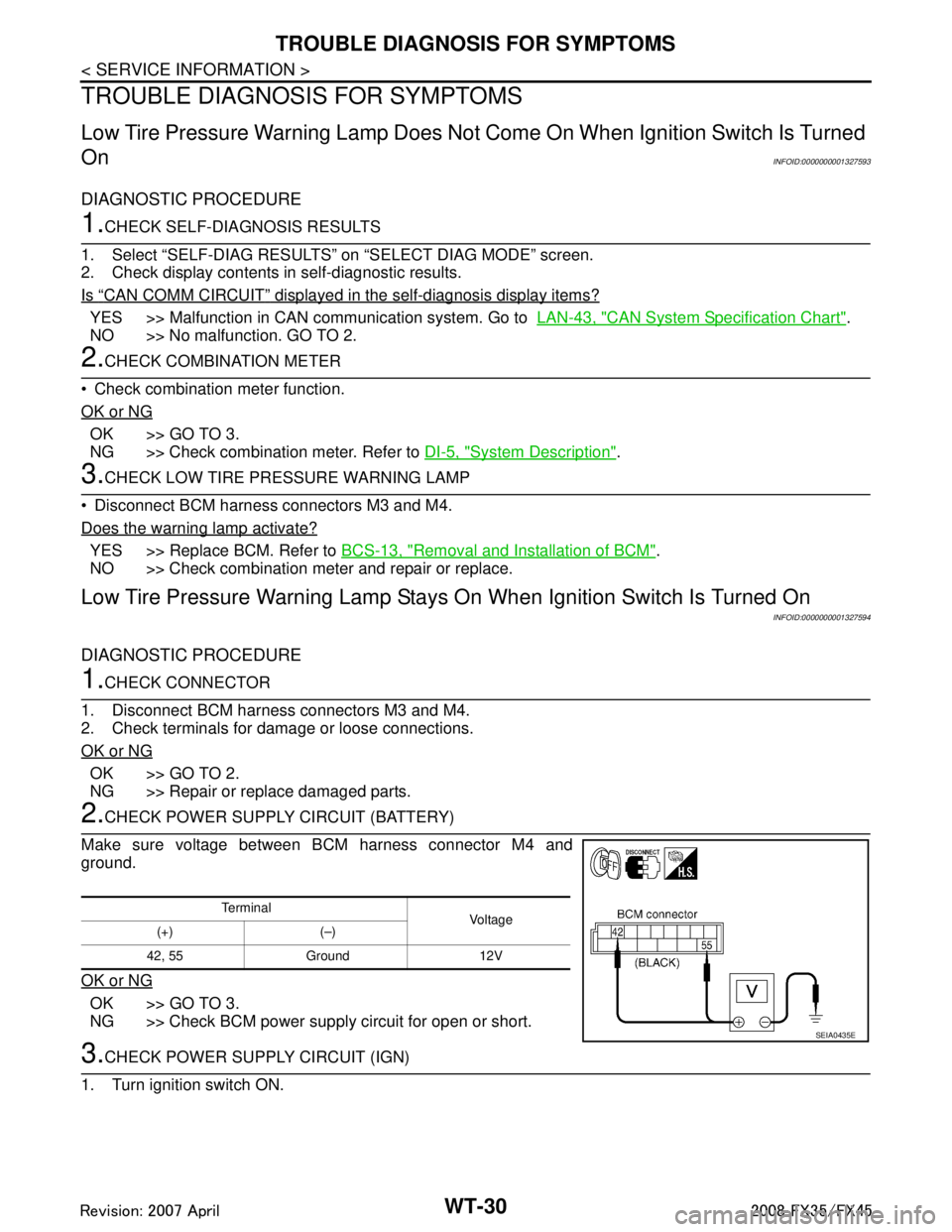
2.CHECK POWER SUPPLY CIRCUIT (BATTERY)
Make sure voltage between BCM harness connector M4 and
ground.
OK or NG
OK >> GO TO 3.
NG >> Check BCM power supply circuit for open or short.
3.CHECK POWER SUPPLY CIRCUIT (IGN)
1. Turn ignition switch ON.
Te r m i n a l Vol tag e
(+) (–)
42, 55 Ground 12V
SEIA0435E
3AA93ABC3ACD3AC03ACA3AC03AC63AC53A913A773A893A873A873A8E3A773A983AC73AC93AC03AC3
3A893A873A873A8F3A773A9D3AAF3A8A3A8C3A863A9D3AAF3A8B3A8C
Page 3880 of 3924

FRONT WIPER AND WASHER SYSTEMWW-5
< SERVICE INFORMATION >
C
DE
F
G H
I
J
L
M A
B
WW
N
O P
to BCM terminals 49 and 52
through grounds M35, M45 and M85,
to IPDM E/R terminals 38 and 60
through grounds E21, E50 and E51,
to combination switch terminal 12
through grounds M35, M45 and M85.
LOW SPEED WIPER OPERATION
When wiper switch is in LOW position, BCM detects low speed wiper ON signal by BCM wiper switch reading
function.
BCM sends front wiper request signal (LO) through CAN communication
from BCM terminals 39 and 40
to IPDM E/R terminals 48 and 49.
When IPDM E/R receives front wiper request signal (LO), it turns ON front wiper relay located in IPDM E/R,
power is supplied
through front wiper relay
through front wiper high relay
through IPDM E/R terminal 21
to front wiper motor terminal 1.
Ground is supplied
to front wiper motor terminal 2
through grounds E21, E50 and E51.
With power and ground supplied, the front wiper motor operates at low speed.
HIGH SPEED WIPER OPERATION
When wiper switch is in HI position, BCM detects high speed wiper ON signal by BCM wiper switch reading
function.
BCM sends front wiper request signal (HI) through CAN communication
from BCM terminals 39 and 40
to IPDM E/R terminals 48 and 49.
When IPDM E/R receives front wiper r equest signal (HI), it turns ON front wiper relay (located in IPDM E/R),
power is supplied
through front wiper relay
through front wiper high relay
through IPDM E/R terminal 31
to front wiper motor terminal 4.
Ground is supplied
to front wiper motor terminal 2
through grounds E21, E50 and E51.
With power and ground supplied, the front wiper motor operates at high speed.
INTERMITTENT OPERATION
Front wiper intermittent operation delay interval is det ermined from a combination of 3 switches (intermittent
operation dial position 1, 2, and 3) and vehicle speed signal.
Speed dependent wiper controlled mode can be changed by the function setting of CONSULT-III or display.
During each intermittent operation delay interval, BCM sends front wiper request signal to IPDM E/R.
Wiper Dial Position Setting
Example: For wiper intermittent dial position 1
Wiper intermittent dial position Intermittent operation
interval Combination switch
INT VOLUME 1 INT VOLUME 2 INT VOLUME 3
1Short
↑
↓
Long ON ON ON
2ONONOFF
3ONOFFOFF
4 OFF OFF OFF
5OFFOFFON
6OFFONON
7 OFF ON OFF
3AA93ABC3ACD3AC03ACA3AC03AC63AC53A913A773A893A873A873A8E3A773A983AC73AC93AC03AC3
3A893A873A873A8F3A773A9D3AAF3A8A3A8C3A863A9D3AAF3A8B3A8C
Page 3890 of 3924
FRONT WIPER AND WASHER SYSTEMWW-15
< SERVICE INFORMATION >
C
DE
F
G H
I
J
L
M A
B
WW
N
O P
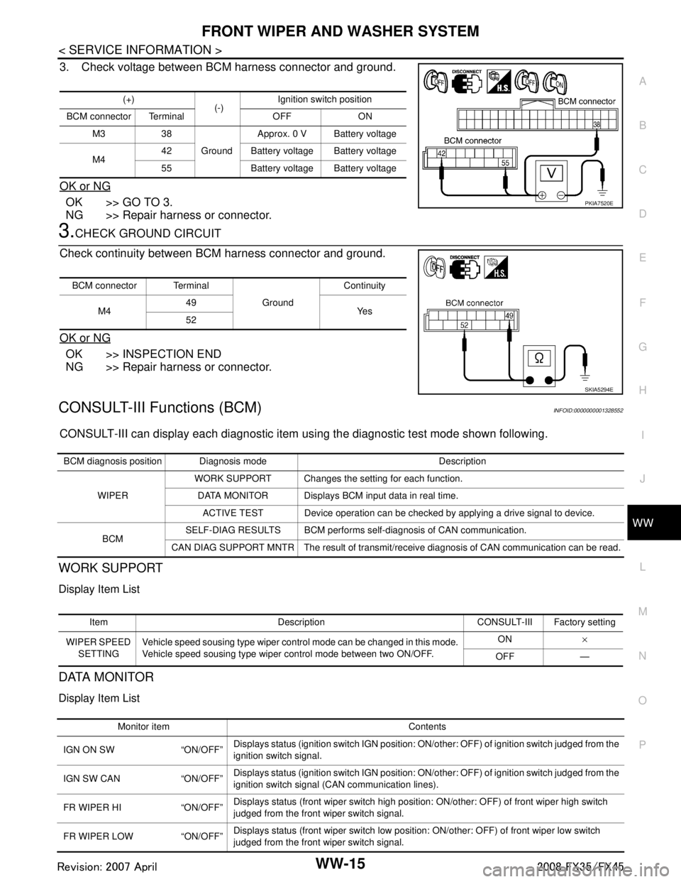
3. Check voltage between BCM harness connector and ground.
OK or NG
OK >> GO TO 3.
NG >> Repair harness or connector.
3.CHECK GROUND CIRCUIT
Check continuity between BCM harness connector and ground.
OK or NG
OK >> INSPECTION END
NG >> Repair harness or connector.
CONSULT-III Functions (BCM)INFOID:0000000001328552
CONSULT-III can display each diagnostic item using the diagnostic test mode shown following.
WORK SUPPORT
Display Item List
DATA MONITOR
Display Item List
(+)
(-)Ignition switch position
BCM connector Terminal OFF ON M3 38 GroundApprox. 0 V Battery voltage
M4 42 Battery voltage Battery voltage
55 Battery voltage Battery voltage
PKIA7520E
BCM connector Terminal
GroundContinuity
M4 49
Ye s
52
SKIA5294E
BCM diagnosis position Diagnosis mode Description
WIPER WORK SUPPORT Changes the setting for each function.
DATA MONITOR Displays BCM input data in real time. ACTIVE TEST Device operation can be checked by applying a drive signal to device.
BCM SELF-DIAG RESULTS BCM performs self-diagnosis of CAN communication.
CAN DIAG SUPPORT MNTR The result of transmit/receive diagnosis of CAN communication can be read.
Item Description CONSULT-III Factory setting
WIPER SPEED SETTING Vehicle speed sousing type wiper control mode can be changed in this mode.
Vehicle speed sousing type wiper control mode between two ON/OFF. ON
×
OFF —
Monitor item Contents
IGN ON SW “ON/OFF” Displays status (ignition switch IGN position: ON/other: OFF) of ignition switch judged from the
ignition switch signal.
IGN SW CAN “ON/OFF” Displays status (ignition switch IGN position: ON/other: OFF) of ignition switch judged from the
ignition switch signal (CAN communication lines).
FR WIPER HI “ON/OFF” Displays status (front wiper switch high position: ON/other: OFF) of front wiper high switch
judged from the front wiper switch signal.
FR WIPER LOW “ON/OFF” Displays status (front wiper switch low position: ON/other: OFF) of front wiper low switch
judged from the front wiper switch signal.
3AA93ABC3ACD3AC03ACA3AC03AC63AC53A913A773A893A873A873A8E3A773A983AC73AC93AC03AC3
3A893A873A873A8F3A773A9D3AAF3A8A3A8C3A863A9D3AAF3A8B3A8C