2008 INFINITI FX35 suspension
[x] Cancel search: suspensionPage 2899 of 3924
LIFTING POINTGI-37
< SERVICE INFORMATION >
C
DE
F
G H
I
J
K L
M B
GI
N
O PLIFTING POINT
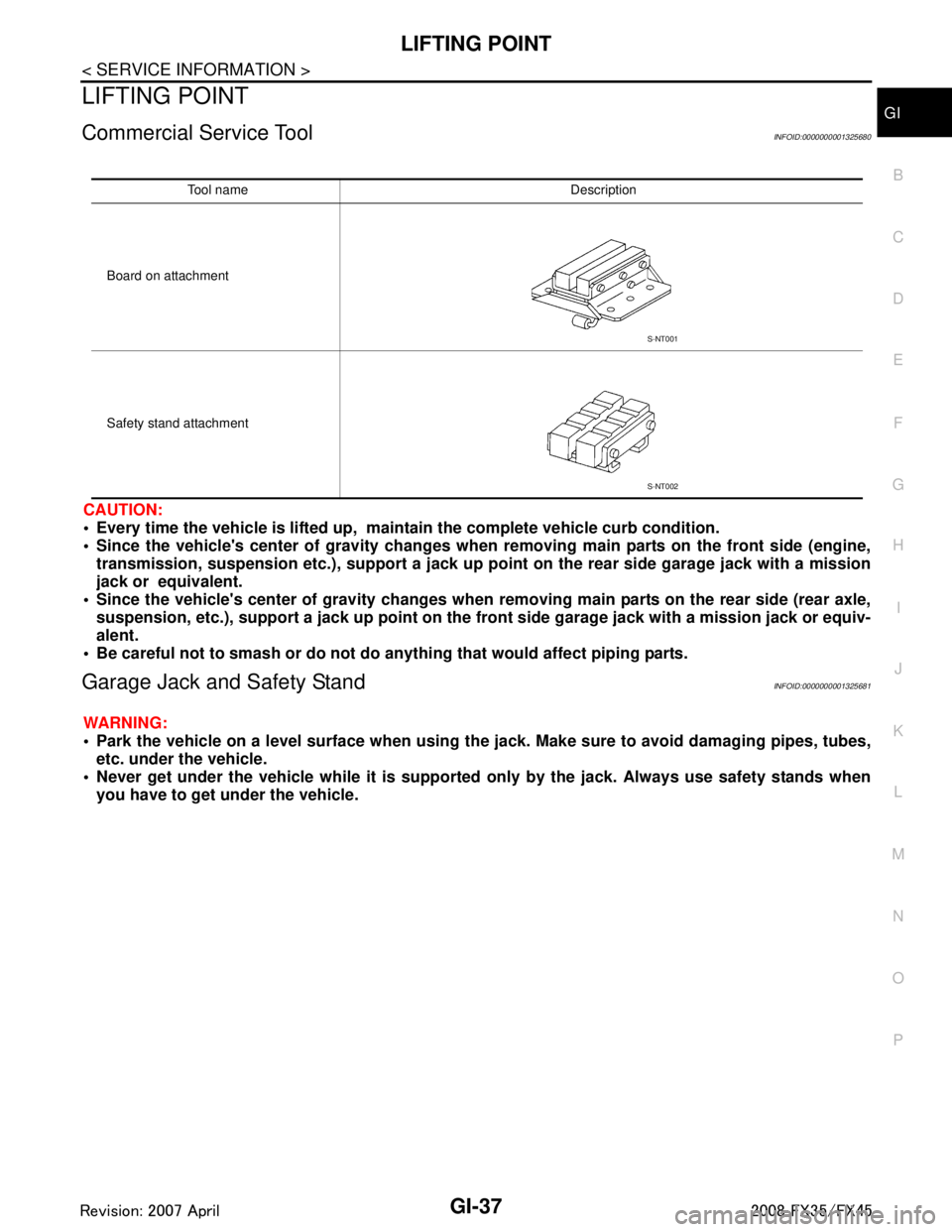
Commercial Service ToolINFOID:0000000001325680
CAUTION:
Every time the vehicle is lifted up, main tain the complete vehicle curb condition.
Since the vehicle's center of gravity changes when removing main parts on the front side (engine,
transmission, suspension etc.), support a jack up poi nt on the rear side garage jack with a mission
jack or equivalent.
Since the vehicle's center of gravity changes when removing main parts on the rear side (rear axle,
suspension, etc.), support a jack up point on the fr ont side garage jack with a mission jack or equiv-
alent.
Be careful not to smash or do not do an ything that would affect piping parts.
Garage Jack and Safety StandINFOID:0000000001325681
WARNING:
Park the vehicle on a level surface when using th e jack. Make sure to avoid damaging pipes, tubes,
etc. under the vehicle.
Never get under the vehicle while it is supported only by the jack. Always use safety stands when
you have to get under the vehicle.
Tool name Description
Board on attachment
Safety stand attachment
S-NT001
S-NT002
3AA93ABC3ACD3AC03ACA3AC03AC63AC53A913A773A893A873A873A8E3A773A983AC73AC93AC03AC3
3A893A873A873A8F3A773A9D3AAF3A8A3A8C3A863A9D3AAF3A8B3A8C
Page 2903 of 3924
TOW TRUCK TOWINGGI-41
< SERVICE INFORMATION >
C
DE
F
G H
I
J
K L
M B
GI
N
O P
AWD MODELS
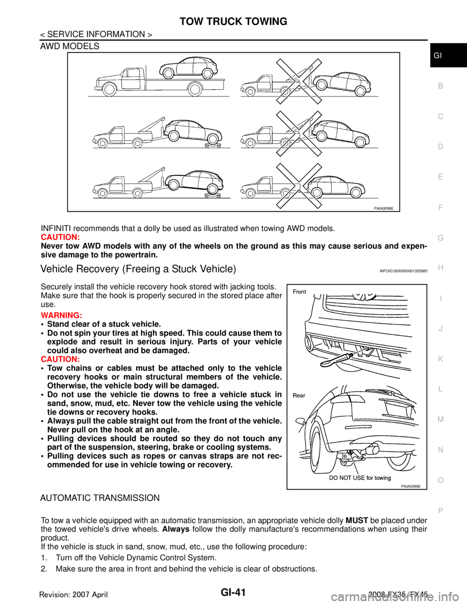
INFINITI recommends that a dolly be used as illustrated when towing AWD models.
CAUTION:
Never tow AWD models with any of the wheels on the ground as this may cause serious and expen-
sive damage to the powertrain.
Vehicle Recovery (Freeing a Stuck Vehicle)INFOID:0000000001325685
Securely install the vehicle recovery hook stored with jacking tools.
Make sure that the hook is properly secured in the stored place after
use.
WARNING:
Stand clear of a stuck vehicle.
Do not spin your tires at high speed. This could cause them to
explode and result in serious injury. Parts of your vehicle
could also overheat and be damaged.
CAUTION:
Tow chains or cables must be attached only to the vehicle recovery hooks or main struct ural members of the vehicle.
Otherwise, the vehicle body will be damaged.
Do not use the vehicle tie downs to free a vehicle stuck in
sand, snow, mud, etc. Never to w the vehicle using the vehicle
tie downs or recovery hooks.
Always pull the cable straight out from the front of the vehicle.
Never pull on the hook at an angle.
Pulling devices should be rout ed so they do not touch any
part of the suspension, steer ing, brake or cooling systems.
Pulling devices such as ropes or canvas straps are not rec- ommended for use in vehicle towing or recovery.
AUTOMATIC TRANSMISSION
To tow a vehicle equipped with an automatic tr ansmission, an appropriate vehicle dolly MUST be placed under
the towed vehicle's drive wheels. Always follow the dolly manufacture's recommendations when using their
product.
If the vehicle is stuck in sand, snow , mud, etc., use the following procedure:
1. Turn off the Vehicle Dynamic Control System.
2. Make sure the area in front and behind the vehicle is clear of obstructions.
PAIA0098E
PAIA0099E
3AA93ABC3ACD3AC03ACA3AC03AC63AC53A913A773A893A873A873A8E3A773A983AC73AC93AC03AC3
3A893A873A873A8F3A773A9D3AAF3A8A3A8C3A863A9D3AAF3A8B3A8C
Page 3318 of 3924
MA-1
MAINTENANCE
C
DE
F
G H
I
J
K
M
SECTION MA
A
B
MA
N
O P
CONTENTS
MAINTENANCE
SERVICE INFORMATION .. ..........................2
PREPARATION .............................................. .....2
Special Service Tool ........................................... ......2
Commercial Service Tool ..........................................2
GENERAL MAINTENANCE ................................3
Explanation of General Maintenance .................. ......3
PERIODIC MAINTENANCE ................................5
Introduction of Periodic Maintenance .................. ......5
Schedule 1 ................................................................5
Schedule 2 ................................................................7
RECOMMENDED FLUIDS AND LUBRI-
CANTS .................................................................
9
Fluids and Lubricants .......................................... ......9
Engine Oil Recommendation ....................................9
Anti-Freeze Coolant Mixture Ratio ..........................10
ENGINE MAINTENANCE (VQ35DE ENGINE) ....11
Checking Drive Belts ........................................... ....11
Drive Belts Tension Adjustment ..............................11
Changing Engine Coolant .......................................12
Checking Fuel Line .................................................15
Changing Air Cleaner Filter .....................................15
Changing Engine Oil ...............................................15
Changing Oil Filter ..................................................16
Changing Spark Plugs (Platinum-Tipped Type) ......17
Checking EVAP Vapor Line ....................................18
ENGINE MAINTENANCE (VK45DE ENGINE) ....19
Checking Drive Belts ........................................... ....19
Tension Adjustment ................................................19
Changing Engine Coolant .......................................19
Checking Fuel Line .............................................. ....22
Changing Air Cleaner Filter .....................................22
Changing Engine Oil ................................................22
Changing Oil Filter ...................................................23
Changing Spark Plugs (Platinum-Tipped Type) ......24
Checking EVAP Vapor Line .....................................25
CHASSIS AND BODY MAINTENANCE ...........26
Checking Exhaust System ................................... ....26
Checking A/T Fluid ..................................................26
Changing A/T Fluid ..................................................27
Checking Transfer Fluid ..........................................28
Changing Transfer Fluid ..........................................28
Checking Propeller Shaft .........................................29
Checking Differential Gear Oil .................................29
Changing Differential Gear Oil .................................29
Balancing Wheels (Bonding Weight Type) ..............30
Tire Rotation ............................................................31
Checking Brake Fluid Level and Leaks ...................32
Checking Brake Line and Cables ............................32
Changing Brake Fluid ..............................................32
Checking Disc Brake ...............................................32
Checking Steering Gear and Linkage ......................33
Checking Power Steering Fluid and Line ................33
Axle and Suspension Parts .....................................34
Drive Shaft ...............................................................34
Lubricating Locks, Hinges and Hood Latch .............35
Checking Seat Belt, Buckles, Retractors, Anchors
and Adjusters ...........................................................
35
SERVICE DATA AND SPECIFICATIONS
(SDS) .................................................................
37
Standard and Limit ..................................................37
3AA93ABC3ACD3AC03ACA3AC03AC63AC53A913A773A893A873A873A8E3A773A983AC73AC93AC03AC3
3A893A873A873A8F3A773A9D3AAF3A8A3A8C3A863A9D3AAF3A8B3A8C
Page 3325 of 3924
MA-8
< SERVICE INFORMATION >
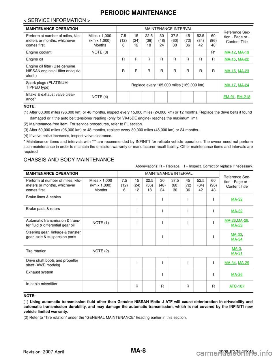
PERIODIC MAINTENANCE
NOTE:
(1) After 60,000 miles (96,000 km) or 48 months, inspect every 15,000 miles (24,000 km) or 12 months. Replace the drive belts if found
damaged or if the auto belt tensioner reading (only for VK45DE engine) reaches the maximum limit.
(2) Maintenance-free item. For service procedures, refer to FL section.
(3) After 60,000 miles (96,000 km) or 48 months, replace every 30,000 miles (48,000 km) or 24 months.
(4) If valve noise increases, inspect valve clearance.
* Maintenance items and intervals with “*” are recommended by INFINITI for reliable vehicle operation. The owner need not perfo rm
such maintenance in order to maintain the emission warranty or manufacturer recall liability. Other maintenance items and inter vals are
required
CHASSIS AND BODY MAINTENANCE
Abbreviations: R = Replace. I = Inspec t. Correct or replace if necessary.
NOTE:
(1) Using automatic transmission fluid other than Genuine NISSAN Matic J ATF will cause deterioration in driveability and
automatic transmission durability, and may damage the automatic transmission, which is not covered by the INFINITI new
vehicle limited warranty.
(2) Refer to “Tire rotation” under the “GENERAL MAINTENANCE” heading earlier in this section.
Engine coolant NOTE (3) R*
MA-12
, MA-19
Engine oil R R R R R R R R MA-15, MA-22
Engine oil filter (Use genuine
NISSAN engine oil filter or equiv-
alent.) RRRR R RRR
MA-16
, MA-23
Spark plugs (PLATINUM-
TIPPED type) Replace every 105,000 miles (169,000 km).
MA-17, MA-24
Intake & exhaust valve clear-
ance* NOTE (4)
EM-91, EM-218
MAINTENANCE OPERATION MAINTENANCE INTERVAL
Reference Sec-
tion - Page or -
Content Title
Perform at number of miles, kilo-
meters or months, whichever
comes first. Miles x 1,000
(km x 1,000)
Months 7.5
(12)
6 15
(24)
12 22.5
(36)
18 30
(48)
24 37.5
(60)
30 45
(72)
36 52.5
(84)
42 60
(96)
48
MAINTENANCE OPERATION MAINTENANCE INTERVAL
Reference Sec-
tion - Page or - Content Title
Perform at number of miles, kilo-
meters or months, whichever
comes first. Miles x 1,000
(km x 1,000) Months 7.5
(12) 6 15
(24) 12 22.5
(36) 18 30
(48) 24 37.5
(60) 30 45
(72) 36 52.5
(84) 42 60
(96) 48
Brake lines & cables IIIIMA-32
Brake pads & rotors
IIIIMA-32
Automatic transmission & trans-
fer fluid & differential gear oilNOTE (1) IIII MA-26,
MA-28,
MA-29
Steering gear, linkage & transfer
gear, axle & suspension parts I I MA-33,
MA-34
Tire rotation NOTE (2) MA-3,
MA-31
Drive shaft boots and propeller
shaft (AWD models) IIII
MA-34, MA-29
Exhaust system
IIMA-26
In-cabin microfilter
RRRRAT C - 1 0 7
3AA93ABC3ACD3AC03ACA3AC03AC63AC53A913A773A893A873A873A8E3A773A983AC73AC93AC03AC3
3A893A873A873A8F3A773A9D3AAF3A8A3A8C3A863A9D3AAF3A8B3A8C
Page 3351 of 3924
MA-34
< SERVICE INFORMATION >
CHASSIS AND BODY MAINTENANCE
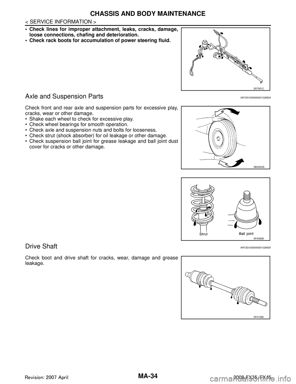
Check lines for improper attachment, leaks, cracks, damage,loose connections, chaf ing and deterioration.
Check rack boots for accumulati on of power steering fluid.
Axle and Suspension PartsINFOID:0000000001328934
Check front and rear axle and suspension parts for excessive play,
cracks, wear or other damage.
Shake each wheel to check for excessive play.
Check wheel bearings for smooth operation.
Check axle and suspension nuts and bolts for looseness.
Check strut (shock absorber) for oil leakage or other damage.
Check suspension ball joint for grease leakage and ball joint dust
cover for cracks or other damage.
Drive ShaftINFOID:0000000001328935
Check boot and drive shaft for cracks, wear, damage and grease
leakage.
SST851C
SMA525A
SFA392B
SFA108A
3AA93ABC3ACD3AC03ACA3AC03AC63AC53A913A773A893A873A873A8E3A773A983AC73AC93AC03AC3
3A893A873A873A8F3A773A9D3AAF3A8A3A8C3A863A9D3AAF3A8B3A8C
Page 3445 of 3924
NOISE, VIBRATION AND HARSHNESS (NVH) TROUBLESHOOTINGPR-3
< SERVICE INFORMATION >
CEF
G H
I
J
K L
M A
B
PR
N
O P
NOISE, VIBRATION AND HARSHN ESS (NVH) TROUBLESHOOTING
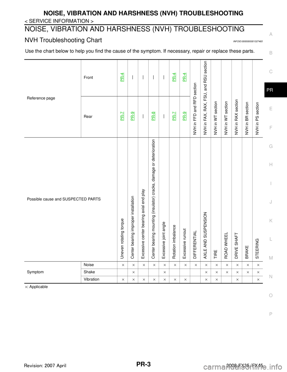
NVH Troubleshooting ChartINFOID:0000000001327465
Use the chart below to help you find t he cause of the symptom. If necessary, repair or replace these parts.
×: Applicable
Reference page
Front
PR-4—
—
—
—
PR-4PR-4
NVH in FFD an d RFD section
NVH in FAX, RAX, FS U, and RSU section
NVH in WT section
NVH in WT section
NVH in RAX section
NVH in BR section
NVH in PS section
RearPR-7PR-9—
PR-8—
PR-7PR-9
Possible cause and SUSPECTED PARTS
Uneven rotating torque
Center bearing improper installation
Excessive center bearing axial end play
Center bearing mounting (insulator) cracks, damage or deterioration
Excessive joint angle
Rotation imbalance
Excessive runout
DIFFERENTIAL
AXLE AND SUSPENSION
TIRE
ROAD WHEEL
DRIVE SHAFT
BRAKE
STEERING
Symptom Noise
××××××××××××××
Shake × × ××××××
Vibration ××××××× ×× × ×
3AA93ABC3ACD3AC03ACA3AC03AC63AC53A913A773A893A873A873A8E3A773A983AC73AC93AC03AC3
3A893A873A873A8F3A773A9D3AAF3A8A3A8C3A863A9D3AAF3A8B3A8C
Page 3461 of 3924
PS-6
< SERVICE INFORMATION >
NOISE, VIBRATION AND HARSHNESS (NVH) TROUBLESHOOTING
NOISE, VIBRATION AND HARSHNESS (NVH) TROUBLESHOOTING
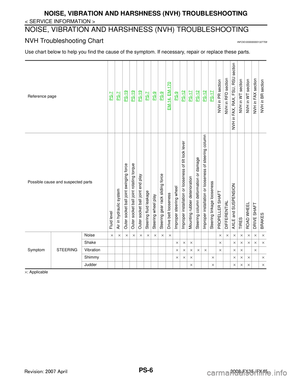
NVH Troubleshooting ChartINFOID:0000000001327708
Use chart below to help you find the cause of the symp tom. If necessary, repair or replace these parts.
×: ApplicableReference page
PS-7PS-7PS-19PS-19PS-19PS-7PS-9PS-9
EM-14
,
EM-170PS-9PS-12PS-17PS-12PS-12PS-17
NVH in PR section
NVH in RFD section
NVH in FAX, RAX, FSU, RSU section NVH in WT section
NVH in WT section
NVH in FAX section
NVH in BR section
Possible cause and suspected parts
Fluid level
Air in hydraulic system
Outer socket ball joint swinging force
Outer socket ball joint rotating torque
Outer socket ball joint end play
Steering fluid leakage
Steering wheel play
Steering gear rack sliding force
Drive belt looseness
Improper steering wheel
Improper installation or looseness of tilt lock lever
Mounting rubber deterioration
Steering column deformation or damage
Improper installation or looseness of steering column
Steering linkage looseness
PROPELLER SHAFT
DIFFERENTIAL
AXLE and SUSPENSION
TIRES
ROAD WHEEL
DRIVE SHAFT
BRAKES
Symptom STEERING Noise
× × ××××× × × ×××××× ×
Shake ××× × ×××× ×
Vibration ××××× × ×× ×
Shimmy ××× × ××× ×
Judder ××××××
3AA93ABC3ACD3AC03ACA3AC03AC63AC53A913A773A893A873A873A8E3A773A983AC73AC93AC03AC3
3A893A873A873A8F3A773A9D3AAF3A8A3A8C3A863A9D3AAF3A8B3A8C
Page 3464 of 3924
STEERING WHEELPS-9
< SERVICE INFORMATION >
C
DE
F
H I
J
K L
M A
B
PS
N
O P
STEERING WHEEL
On-Vehicle Inspection and ServiceINFOID:0000000001327712
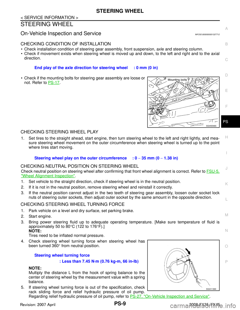
CHECKING CONDITION OF INSTALLATION
Check installation condition of steering gear assemb ly, front suspension, axle and steering column.
Check if movement exists when steering wheel is mo ved up and down, to the left and right and to the axial
direction.
Check if the mounting bolts for steering gear assembly are loose or not. Refer to PS-17
.
CHECKING STEERING WHEEL PLAY
1. Set tires to the straight ahead, start engine, then turn steering wheel to the left and right lightly, and mea-
sure steering wheel movement on the outer circumfe rence when steering wheel is turned up to the point
where tires start moving.
CHECKING NEUTRAL POSITION ON STEERING WHEEL
Check neutral position on steering wheel after confirming that front wheel alignment is correct. Refer to FSU-5,
"Wheel Alignment Inspection".
1. Set vehicle to the straight direction, chec k if steering wheel is in the neutral position.
2. If it is not in the neutral position, remo ve steering wheel and reinstall it correctly.
3. If the neutral position cannot adjust in the two teeth of steering gear assembly, loosen outer socket lock
nuts of steering outer sockets, then adjust outer so cket by the same amount in the opposite direction.
CHECKING STEERING WHEEL TURNING FORCE
1. Park vehicle on a level and dry surface, set parking brake.
2. Start engine.
3. Bring power steering fluid up to adequate operating te mperature. [Make sure temperature of fluid is
approximately 50 to 80 °C (122 to 176 °F).]
NOTE:
Tires need to be inflated normal pressure.
4. Check steering wheel turning force when steering wheel has been turned 360 ° from neutral position.
NOTE:
Multiply the distance L from the hook of spring balance to the
center of steering wheel by the measurement value with a spring
balance.
5. If steering wheel turning force is out of the specification, check
rack sliding force and relief hydraulic pressure of oil pump.
Regarding relief hydraulic pressure of oil pump, refer to PS-27, "
On-Vehicle Inspection and Service".
End play of the axle direction for steering wheel : 0 mm (0 in)
SGIA0546E
Steering wheel play on the
outer circumference : 0 − 35 mm (0 − 1.38 in)
Steering wheel turning force : Less than 7.45 N·m (0.76 kg-m, 66 in-lb)
SGIA1136E
3AA93ABC3ACD3AC03ACA3AC03AC63AC53A913A773A893A873A873A8E3A773A983AC73AC93AC03AC3
3A893A873A873A8F3A773A9D3AAF3A8A3A8C3A863A9D3AAF3A8B3A8C