Page 3713 of 3924

SE-74
< SERVICE INFORMATION >
AUTOMATIC DRIVE POSITIONER
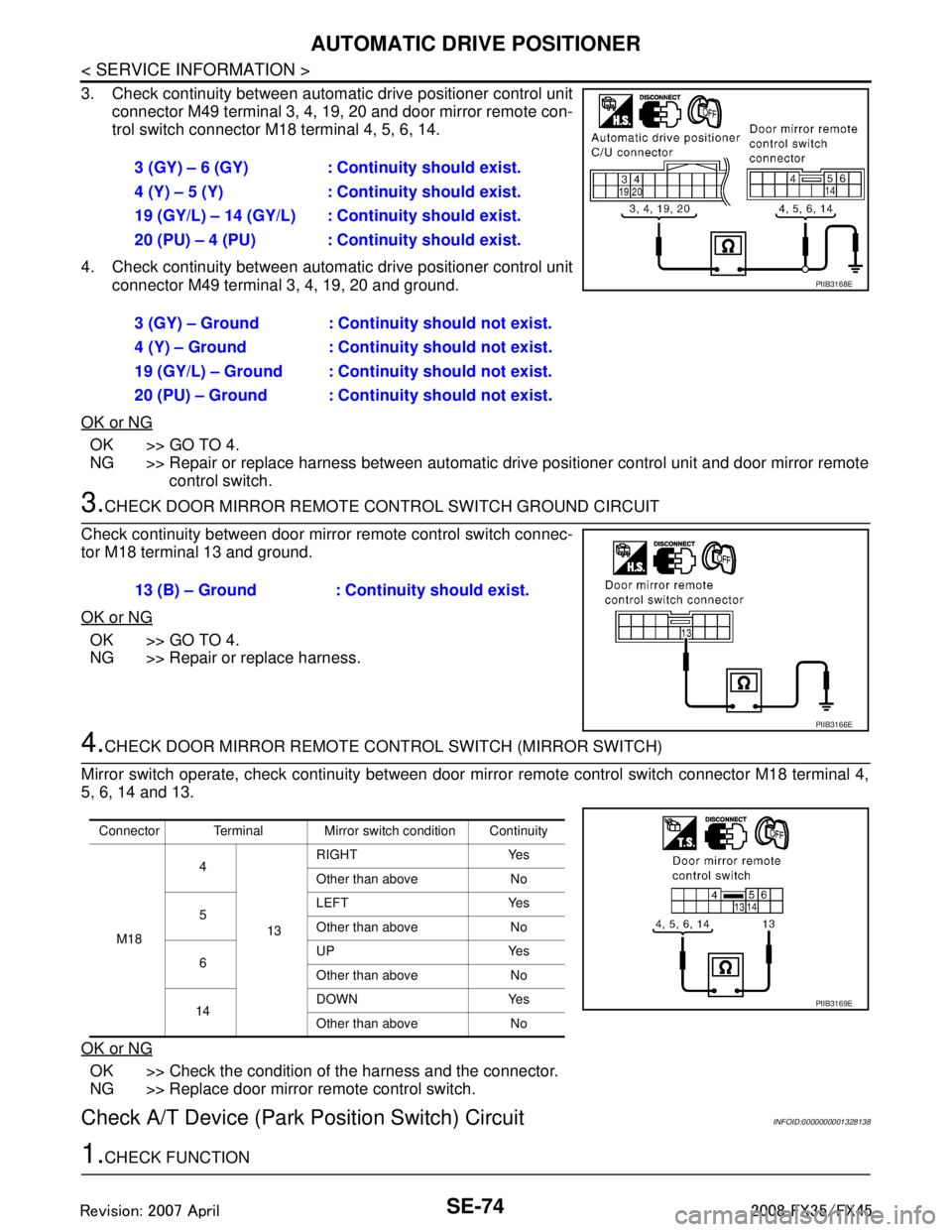
3. Check continuity between automatic drive positioner control unit
connector M49 terminal 3, 4, 19, 20 and door mirror remote con-
trol switch connector M18 terminal 4, 5, 6, 14.
4. Check continuity between automat ic drive positioner control unit
connector M49 terminal 3, 4, 19, 20 and ground.
OK or NG
OK >> GO TO 4.
NG >> Repair or replace harness between automatic drive positioner control unit and door mirror remote
control switch.
3.CHECK DOOR MIRROR REMOTE CONTROL SWITCH GROUND CIRCUIT
Check continuity between door mirro r remote control switch connec-
tor M18 terminal 13 and ground.
OK or NG
OK >> GO TO 4.
NG >> Repair or replace harness.
4.CHECK DOOR MIRROR REMOTE CONTROL SWITCH (MIRROR SWITCH)
Mirror switch operate, check continuity between door mi rror remote control switch connector M18 terminal 4,
5, 6, 14 and 13.
OK or NG
OK >> Check the condition of the harness and the connector.
NG >> Replace door mirror remote control switch.
Check A/T Device (Park Position Switch) CircuitINFOID:0000000001328138
1.CHECK FUNCTION3 (GY) – 6 (GY) : Continuity should exist.
4 (Y) – 5 (Y) : Continuity should exist.
19 (GY/L) – 14 (GY/L) : Co
ntinuity should exist.
20 (PU) – 4 (PU) : Continuity should exist.
3 (GY) – Ground : Continuity should not exist.
4 (Y) – Ground : Continuity should not exist.
19 (GY/L) – Ground : Continuity should not exist.
20 (PU) – Ground : Continuity should not exist.
PIIB3168E
13 (B) – Ground : Continuity should exist.
PIIB3166E
Connector Terminal Mirror switch condition Continuity
M18 4
13RIGHT Yes
Other than above No
5 LEFT Yes
Other than above No
6 UP Yes
Other than above No
14 DOWN Yes
Other than above No
PIIB3169E
3AA93ABC3ACD3AC03ACA3AC03AC63AC53A913A773A893A873A873A8E3A773A983AC73AC93AC03AC3
3A893A873A873A8F3A773A9D3AAF3A8A3A8C3A863A9D3AAF3A8B3A8C
Page 3735 of 3924

SE-96
< SERVICE INFORMATION >
REAR SEAT
REMOVAL
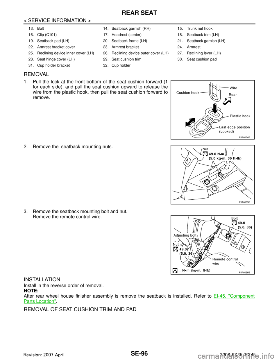
1. Pull the lock at the front bottom of the seat cushion forward (1
for each side), and pull the seat cushion upward to release the
wire from the plastic hook, then pull the seat cushion forward to
remove.
2. Remove the seatback mounting nuts.
3. Remove the seatback mounting bolt and nut. Remove the remote control wire.
INSTALLATION
Install in the reverse order of removal.
NOTE:
After rear wheel house finisher assembly is remove the seatback is installed. Refer to EI-45, "
Component
Parts Location".
REMOVAL OF SEAT CUSHION TRIM AND PAD
13. Bolt 14. Seatback garnish (RH) 15. Trunk net hook
16. Clip (C101) 17. Headrest (center) 18. Seatback trim (LH)
19. Seatback pad (LH) 20. Seatback frame (LH) 21. Seatback garnish (LH)
22. Armrest bracket cover 23. Armrest bracket 24. Armrest
25. Reclining device inner cover (LH) 26. Reclining device outer cover (LH) 27. Reclining lever (LH)
28. Seat hinge cover (LH) 29. Seat cushion trim 30. Seat cushion pad
31. Cup holder bracket 32. Cup holder
PIIA6034E
PIIA6035E
PIIA6036E
3AA93ABC3ACD3AC03ACA3AC03AC63AC53A913A773A893A873A873A8E3A773A983AC73AC93AC03AC3
3A893A873A873A8F3A773A9D3AAF3A8A3A8C3A863A9D3AAF3A8B3A8C
Page 3737 of 3924
SE-98
< SERVICE INFORMATION >
REAR SEAT
REMOVAL OF REMOTE CONTROL LEVER
1. Remove the rear seat. Refer to "REMOVAL".
2. Remove the luggage side finisher assembly. Refer to EI-45, "
Component Parts Location".
3. Remove the remote control lever.
4. Remove the remote control lever mounting bolt.
5. Remove the remote control lever assembly.
INSTALLATION OF REMOTE CONTROL LEVER
Install in the reverse order of removal.
PIIB1434E
1. Remote control wire 2. Bolt 3. Remote control lever
3AA93ABC3ACD3AC03ACA3AC03AC63AC53A913A773A893A873A873A8E3A773A983AC73AC93AC03AC3
3A893A873A873A8F3A773A9D3AAF3A8A3A8C3A863A9D3AAF3A8B3A8C
Page 3850 of 3924
WT-10
< SERVICE INFORMATION >
TIRE PRESSURE MONITORING SYSTEM
TIRE PRESSURE MONITORING SYSTEM
System ComponentINFOID:0000000001327576
System DescriptionINFOID:0000000001327577
TRANSMITTER
A sensor-transmitter integrated with a valve is installed on a wheel,
and transmits a detected air pressure signal in the form of a radio
wave.
REMOTE KEYLESS ENTRY RECEIVER
The remote keyless entry receiver receives the air pressure signal
transmitted by the transmitter in each wheel.
BCM (BODY CONTROL MODULE)
SEIA0599E
SEIA0521E
SEIA0431E
3AA93ABC3ACD3AC03ACA3AC03AC63AC53A913A773A893A873A873A8E3A773A983AC73AC93AC03AC3
3A893A873A873A8F3A773A9D3AAF3A8A3A8C3A863A9D3AAF3A8B3A8C
Page 3851 of 3924

TIRE PRESSURE MONITORING SYSTEMWT-11
< SERVICE INFORMATION >
C
DF
G H
I
J
K L
M A
B
WT
N
O P
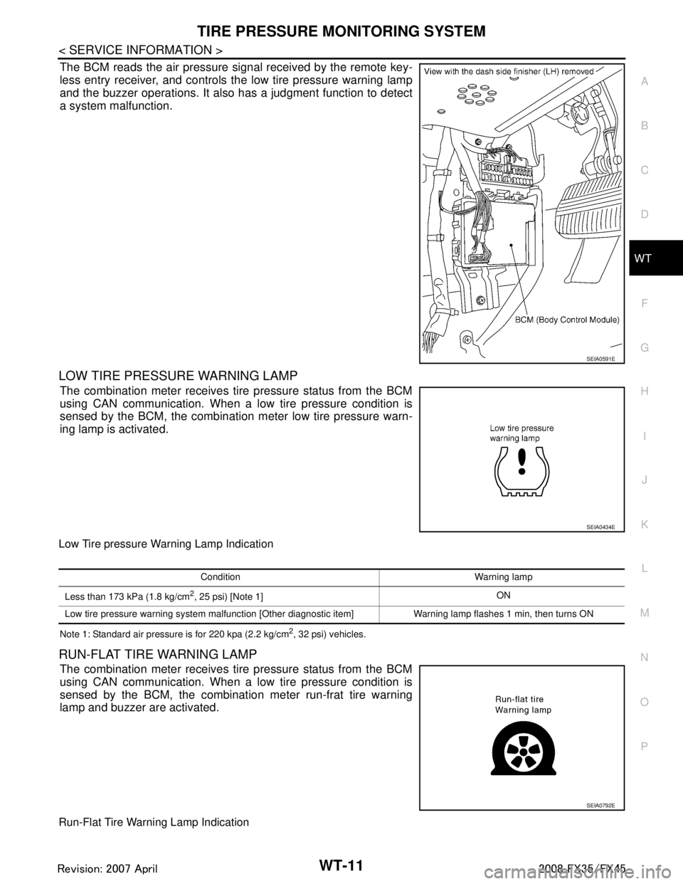
The BCM reads the air pressure signal received by the remote key-
less entry receiver, and controls the low tire pressure warning lamp
and the buzzer operations. It also has a judgment function to detect
a system malfunction.
LOW TIRE PRESSURE WARNING LAMP
The combination meter receives tire pressure status from the BCM
using CAN communication. When a low tire pressure condition is
sensed by the BCM, the combination meter low tire pressure warn-
ing lamp is activated.
Low Tire pressure Warning Lamp Indication
Note 1: Standard air pressure is for 220 kpa (2.2 kg/cm2, 32 psi) vehicles.
RUN-FLAT TIRE WARNING LAMP
The combination meter receives tire pressure status from the BCM
using CAN communication. When a low tire pressure condition is
sensed by the BCM, the combination meter run-frat tire warning
lamp and buzzer are activated.
Run-Flat Tire Warning Lamp Indication
SEIA0591E
SEIA0434E
Condition Warning lamp
Less than 173 kPa (1.8 kg/cm
2, 25 psi) [Note 1] ON
Low tire pressure warning system malfunction [Other diagnostic item] Warning lamp flashes 1 min, then turns ON
SEIA0792E
3AA93ABC3ACD3AC03ACA3AC03AC63AC53A913A773A893A873A873A8E3A773A983AC73AC93AC03AC3
3A893A873A873A8F3A773A9D3AAF3A8A3A8C3A863A9D3AAF3A8B3A8C
Page 3868 of 3924

WT-28
< SERVICE INFORMATION >
TROUBLE DIAGNOSIS FOR SELF-DIAGNOSTIC ITEMS
TROUBLE DIAGNOSIS FOR SELF-DIAGNOSTIC ITEMS
Transmitter or Control Unit (BCM)INFOID:0000000001327589
MALFUNCTION CODE NO. 21, 22, 23 OR 24
1.CHECK CONTROL UNIT
Drive for several minutes. Check all tire pr essures with CONSULT-III “DATA MONITOR ITEM”.
Are all tire pressures displayed 0 kPa?
YES >> GO TO 2.
NO >> GO TO 3.
2.CHECK REMOTE KEYLESS EN TRY RECEIVER CONNECTOR
1. Disconnect remote keyless entry receiver harness connector M98.
2. Check terminals for damage or loose connection.
3. Reconnect harness connector.
OK or NG
OK >> Replace BCM refer to BCS-13, "Removal and Installation of BCM", then GO TO 3.
NG >> Repair or replace remote keyless entry receiver harness connector.
3.ID REGISTRATION
Perform ID registration of all transmitters.
Is there any tire that ID can not be registered to?
YES >> Replace transmitter of the tire, then GO TO 5.
NO >> GO TO 4.
4.VEHICLE DRIVING
Drive at a speed of 40 km/h (25 MPH) or more for several minutes without stopping. Check all tire pressures with CONSULT-III “DATA MONITOR ITEM” within 15 minutes after vehicle speed
becomes 17 km/h (11 MPH).
Does
“DATA MONITOR ITEM” display tire pressure as normal without any warning lamp?
YES >> INSPECTION END
NO >> GO TO 5.
5.ID REGISTRATION AND VEHICLE DRIVING
1. Perform ID registration of all transmitters.
2. Drive at a speed of 40 km/h (25 MPH) or more fo r 3 minutes, and then drive the vehicle at any speed for
10 minutes. Then check all tire pressures with CO NSULT-III “DATA MONITOR ITEM” within 5 minutes.
Does
“DATA MONITOR ITEM” display tire pressure as normal without any warning lamp?
YES >> INSPECTION END
NO >> Go to the inspection applicable to DTC.
Transmitter - 1INFOID:0000000001327590
MALFUNCTION CODE NO. 31, 32, 33, 34, 41, 42, 43, 44, 45, 46, 47 OR 48
1.ID REGISTRATION (CORRECTION OF TRANSMITTER LOCATION)
1. Perform ID registration of all transmitters.
2. Drive at a speed of 40 km/h (25 MPH) or more fo r 3 minutes, and then drive the vehicle at any speed for
10 minutes.
>> GO TO 2.
2.REPLACE TRANSMITTER
1. Check low tire pressure warning condition again, replace malfunctioning transmitter.
2. Perform ID registration of all transmitters.
Can ID registration of all transmitters be completed?
3AA93ABC3ACD3AC03ACA3AC03AC63AC53A913A773A893A873A873A8E3A773A983AC73AC93AC03AC3
3A893A873A873A8F3A773A9D3AAF3A8A3A8C3A863A9D3AAF3A8B3A8C