2008 INFINITI FX35 belt
[x] Cancel search: beltPage 1119 of 3924
![INFINITI FX35 2008 Service Manual
CO-48
< SERVICE INFORMATION >[VK45DE]
COOLING FAN
COOLING FAN
Component (Crankshaft Driven type)INFOID:0000000001325877
Removal and InstallationINFOID:0000000001325878
REMOVAL
1. Remove air duct (inl INFINITI FX35 2008 Service Manual
CO-48
< SERVICE INFORMATION >[VK45DE]
COOLING FAN
COOLING FAN
Component (Crankshaft Driven type)INFOID:0000000001325877
Removal and InstallationINFOID:0000000001325878
REMOVAL
1. Remove air duct (inl](/manual-img/42/57017/w960_57017-1118.png)
CO-48
< SERVICE INFORMATION >[VK45DE]
COOLING FAN
COOLING FAN
Component (Crankshaft Driven type)INFOID:0000000001325877
Removal and InstallationINFOID:0000000001325878
REMOVAL
1. Remove air duct (inlet). Refer to
EM-173, "Component".
2. Remove engine front undercover with power tool.
3. Remove radiator shroud (lower). Refer to CO-40, "
Component".
4. Remove drive belts. Refer to EM-170, "
Component".
5. Remove fan coupling and cooling fan assembly. CAUTION:
Do not damage or scratch ra diator core when removing.
6. Remove cooling fan from fan coupling.
INSPECTION AFTER REMOVAL
Fan Coupling
Inspect fan coupling for oil leakage and bimetal conditions.
If anything is found, replace fan coupling.
Cooling Fan
Inspect cooling fan for crack or unusual bend.
If anything is found, replace cooling fan.
INSTALLATION
Note the following, install in the reverse order of removal.
Install cooling fan with its front mark “F” facing fr ont of vehicle. Refer to "Removal and Installation".
1. Cooling fan 2. Fan coupling 3. Fan and water pump pulley
4. Water pump
PBIC1537E
SLC072
3AA93ABC3ACD3AC03ACA3AC03AC63AC53A913A773A893A873A873A8E3A773A983AC73AC93AC03AC3
3A893A873A873A8F3A773A9D3AAF3A8A3A8C3A863A9D3AAF3A8B3A8C
Page 1121 of 3924
![INFINITI FX35 2008 Service Manual
CO-50
< SERVICE INFORMATION >[VK45DE]
WATER PUMP
WATER PUMP
ComponentINFOID:0000000001325882
Removal and InstallationINFOID:0000000001325883
CAUTION:
When removing water pump, be careful no
t to ge INFINITI FX35 2008 Service Manual
CO-50
< SERVICE INFORMATION >[VK45DE]
WATER PUMP
WATER PUMP
ComponentINFOID:0000000001325882
Removal and InstallationINFOID:0000000001325883
CAUTION:
When removing water pump, be careful no
t to ge](/manual-img/42/57017/w960_57017-1120.png)
CO-50
< SERVICE INFORMATION >[VK45DE]
WATER PUMP
WATER PUMP
ComponentINFOID:0000000001325882
Removal and InstallationINFOID:0000000001325883
CAUTION:
When removing water pump, be careful no
t to get engine coolant on drive belts.
Water pump can not be disassembled and should be replaced as a unit.
After installing water pump, connect hose and clamp securely, then check for leaks using radiator
cap tester (commercial service tool) and radiator cap tester adapter (commercial service tool).
REMOVAL
1. Drain engine coolant from drain plugs on radiator and both side of cylinder block. Refer to CO-37, "Chang-
ing Engine Coolant" and EM-242, "Disassembly and Assembly".
CAUTION:
Perform this step when engine is cold.
Do not spill engine coolant on drive belts.
2. Remove following parts: Engine front undercover
Air duct (inlet): Refer to EM-173, "
Component".
Alternator, water pump and A/C compressor belt: Refer to EM-170, "
Component".
3. Remove fan coupling with cooling fan, and then fan and water pump pulley.
4. Remove water pump. Engine coolant will leak from cylinder block, so have a receptacle ready under vehicle.
CAUTION:
Handle the water pump vane so that it does not contact any other parts.
Do not disassemble water pump.
INSPECTION AFTER REMOVAL
1. Fan and water pump pulley 2. Water pump 3. Gasket
PBIC1538E
3AA93ABC3ACD3AC03ACA3AC03AC63AC53A913A773A893A873A873A8E3A773A983AC73AC93AC03AC3
3A893A873A873A8F3A773A9D3AAF3A8A3A8C3A863A9D3AAF3A8B3A8C
Page 1124 of 3924
![INFINITI FX35 2008 Service Manual
THERMOSTAT AND WATER CONTROL VALVECO-53
< SERVICE INFORMATION > [VK45DE]
C
D
E
F
G H
I
J
K L
M A
CO
NP
O
Refer to
GI-8, "Component" for symbols in the figure.
Removal and InstallationINFOID:000000 INFINITI FX35 2008 Service Manual
THERMOSTAT AND WATER CONTROL VALVECO-53
< SERVICE INFORMATION > [VK45DE]
C
D
E
F
G H
I
J
K L
M A
CO
NP
O
Refer to
GI-8, "Component" for symbols in the figure.
Removal and InstallationINFOID:000000](/manual-img/42/57017/w960_57017-1123.png)
THERMOSTAT AND WATER CONTROL VALVECO-53
< SERVICE INFORMATION > [VK45DE]
C
D
E
F
G H
I
J
K L
M A
CO
NP
O
Refer to
GI-8, "Component" for symbols in the figure.
Removal and InstallationINFOID:0000000001325885
REMOVAL
1. Drain engine coolant from drain plugs on radiat or and both side of cylinder block. Refer to CO-37, "Chang-
ing Engine Coolant" and EM-242, "Disassembly and Assembly".
CAUTION:
Perform this step when engine is cold.
Do not spill engine coolant on drive belts.
2. Remove engine cover with power tool. Refer to EM-169, "
Component".
3. Remove air duct (inlet). Refer to EM-173, "
Component".
4. Disconnect water suction hose from water inlet.
5. Remove water inlet and thermostat. CAUTION:
Do not disassemble thermostat.
6. Remove intake manifolds (upper and lower). Refer to EM-175, "
Component".
7. Disconnect radiator hose (upper) and wa ter hoses from thermostat housing.
8. Disconnect heater hoses from water outlet and heater pipe.
9. Remove thermostat housing, water outlet pipe, water connector, water control valve, water outlet and heater pipe.
CAUTION:
Do not disassemble water control valve.
INSPECTION AFTER REMOVAL
Make sure that valves both in thermostat and water c ontrol valve are completely closing at normal tempera-
ture.
Place a thread so that it is caught in the valves of the thermostat
and water control valve. Immerse fully in a container filled with
water. Heat while stirring. (The example in the figure shows ther-
mostat.)
The valve opening temperature is the temperature at which the valve opens and falls from the thread.
Continue heating. Check the maximum valve lift. NOTE:
The maximum valve lift standard temperature for water control
valve is the reference value.
After checking the maximum valve lift, lower the water tempera-
ture and check the valve closing temperature.
Standard values:
If the malfunctioning condition, when closing valve at nor mal temperature, or measured values are out of the
standard, replace thermostat and/or water control valve.
INSTALLATION
Note the following, and install in the reverse order of removal.
CAUTION:
Be careful not to spill engine coolant over en gine room. Use rag to absorb engine coolant.
Thermostat and Water Control Valve
D. To heater core E. To cylinder head (left bank) F. To cylinder head (right bank)
G. To intake manifold adapter
SLC252B
Thermostat Water control valve
Valve opening temperature 80 - 84 °C (176 - 183 °F) 93.5 - 96.5 °C (200 - 206 °F)
Maximum valve lift More than 10 mm/95
°C
(0.39 in/203 °F) More than 8 mm/108
°C
(0.315 in/226 °F)
Valve closing temperature 77 °C (171 °F) 90 °C (194 °F)
3AA93ABC3ACD3AC03ACA3AC03AC63AC53A913A773A893A873A873A8E3A773A983AC73AC93AC03AC3
3A893A873A873A8F3A773A9D3AAF3A8A3A8C3A863A9D3AAF3A8B3A8C
Page 1127 of 3924

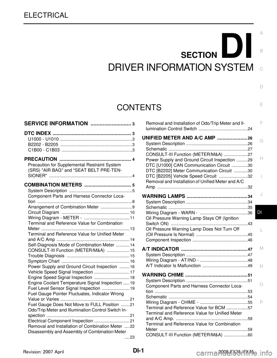
DI-1
ELECTRICAL
C
DE
F
G H
I
J
L
M
SECTION DI
A
B
DI
N
O P
CONTENTS
DRIVER INFORMATION SYSTEM
SERVICE INFORMATION .. ..........................3
DTC INDEX ..................................................... .....3
U1000 - U1010 .................................................... ......3
B2202 - B2205 ..........................................................3
C1B00 - C1B03 .........................................................3
PRECAUTION .....................................................4
Precaution for Supplemental Restraint System
(SRS) "AIR BAG" and "SEAT BELT PRE-TEN-
SIONER" ............................................................. ......
4
COMBINATION METERS ...................................5
System Description ............................................. ......5
Component Parts and Harness Connector Loca-
tion ............................................................................
8
Arrangement of Combination Meter ..........................9
Circuit Diagram .......................................................10
Wiring Diagram - METER - .....................................11
Terminal and Reference Value for Combination
Meter .......................................................................
13
Terminal and Reference Value for Unified Meter
and A/C Amp ...........................................................
14
Self-Diagnosis Mode of Combination Meter ............14
CONSULT-III Function (METER/M&A) ...................15
Trouble Diagnosis ...................................................15
Symptom Chart .......................................................16
Power Supply and Ground Circuit Inspection .........16
Vehicle Speed Signal Inspection .............................17
Engine Speed Signal Inspection .............................18
Engine Coolant Temperature Signal Inspection ......19
Fuel Level Sensor Signal Inspection .......................19
Fuel Gauge Pointer Fluctuates, Indicator Wrong
Value or Varies ........................................................
21
Fuel Gauge Does Not Move to FULL Position ........21
Odo/Trip Meter and Illumination Control Switch In-
spection ............................................................... ....
21
Electrical Component Inspection .............................21
Removal and Installation of Combination Meter .....22
Disassembly and Assembly of Combination Meter
....
23
Removal and Installation of Odo/Trip Meter and Il-
lumination Control Switch .................................... ....
24
UNIFIED METER AND A/C AMP ......................26
System Description ..................................................26
Schematic ................................................................27
CONSULT-III Function (METER/M&A) ....................27
Power Supply and Ground Circuit Inspection ..........29
DTC [U1000] CAN Communication Circuit ..............30
DTC [B2202] Meter Commun ication Circuit ............30
DTC [B2205] Vehicle Speed Circuit .................... ....32
Removal and Installation of Unified Meter and A/C
Amp .........................................................................
32
WARNING LAMPS ............................................34
System Description .............................................. ....34
Schematic ................................................................35
Wiring Diagram - WARN - .......................................36
Oil Pressure Warning Lamp Stays Off (Ignition
Switch ON) .......................................................... ....
43
Oil Pressure Warning Lamp Does Not Turn Off
(Oil Pressure Is Normal) ...................................... ....
45
Component Inspection .............................................46
A/T INDICATOR ................................................47
System Description ..................................................47
Wiring Diagram - AT/IND - .......................................48
A/T Indicator Is Malfunction .....................................49
WARNING CHIME .............................................51
System Description .............................................. ....51
Component Parts and Harness Connector Loca-
tion ...........................................................................
53
Schematic ................................................................54
Wiring Diagram - CHIME - .......................................55
Terminal and Reference Value for BCM ..................57
Terminal and Reference Value for Unified Meter
and A/C Amp. ...................................................... ....
59
Terminal and Reference Value for Combination
Meter .......................................................................
59
CONSULT-III Function (METER/M&A) ....................60
3AA93ABC3ACD3AC03ACA3AC03AC63AC53A913A773A893A873A873A8E3A773A983AC73AC93AC03AC3
3A893A873A873A8F3A773A9D3AAF3A8A3A8C3A863A9D3AAF3A8B3A8C
Page 1128 of 3924

DI-2
CONSULT-III Function (BCM) ................................60
Trouble Diagnosis ...................................................61
Symptom Chart .......................................................61
Power Supply and Ground Circuit Inspection .........61
Combination Meter Buzzer Circuit Inspection .........62
Front Door Switch (Driver Side) Signal Inspection ...63
Key Switch Signal Inspection (Without Intelligent
Key) ..................................................................... ...
64
Key Switch and Ignition Knob Switch Signal In-
spection (With Intelligent Key, When Mechanical
Key Is Used) ........................................................ ...
65
Lighting Switch Signal Inspection ...........................66
Seat Belt Buckle Switch (Driver Side) Signal In-
spection ............................................................... ...
66
Component Inspection ............................................67
LANE DEPARTURE WARNING SYSTEM ........69
Precaution for Lane Departure Warning (LDW)
system ................................................................. ...
69
System Description .................................................69
Action Test ..............................................................71
Camera Aiming Adjustment ....................................71
Component Parts and Harness Connector Loca-
tion ..........................................................................
76
Schematic ...............................................................77
Wiring Diagram - LDW - .........................................78
Terminal and Reference Value for LDW Camera
Unit .........................................................................
81
CONSULT-III Function (LDW) ................................81
Trouble Diagnosis ...................................................83
Preliminary Check ..................................................84
Power Supply and Ground Circuit Inspection .........84
DTC [C1B00] CAMERA UNIT MALF ......................85
DTC [C1B01] CAM AIMING INCMP .......................85
DTC [C1B02] VHCL SPD DATA MALF ..................85
DTC [C1B03] ABNRML TEMP DETECT ................86
DTC [U1000] CAN COMM CIRCUIT ......................86
DTC [U1010] CONTROL UNIT (CAN) ....................86
LDW Chime Circuit Inspection ................................86
LDW Switch Circuit Inspection ...............................88
LDW Indicator Lamp Circuit Inspection ..................90
Turn Signal Input Inspection ................................ ...91
Electrical Component Inspection ............................91
Removal and Installation for LDW Camera Unit .....91
Removal and Installation for LDW Chime ............ ...91
Removal and Installation for LDW Switch ...............92
CAN COMMUNICATION ...................................93
System Description .............................................. ...93
CAN Communication Unit .......................................93
COMPASS .........................................................94
Precaution for Compass ...................................... ...94
System Description .................................................94
Troubleshooting ......................................................94
Zone Variation Setting Procedure ...........................95
Calibration Procedure .............................................95
Wiring Diagram - COMPAS - ..................................97
Removal and Installation of Compass ....................97
CLOCK ..............................................................98
Wiring Diagram - CLOCK - .................................. ...98
Removal and Installation of Clock ...........................98
REAR VIEW MONITOR ....................................100
System Description .............................................. .100
Component Parts and Harness Connector Loca-
tion ........................................................................
101
Schematic .............................................................102
Wiring Diagram - R/VIEW - ...................................103
Terminal and Reference Value for Rear View
Camera Control Unit .............................................
106
CONSULT-III Function (REARVIEW CAMERA) ...106
Side Distance Guideline Correction ......................107
Power Supply and Ground Circuit Inspection .......108
Rear View Is Not Displayed with the A/T Selector
Lever in R-Position ................................................
108
The Rear View Image Is Distorted ........................112
Removal and Installation of Rear View Camera
Control Unit .......................................................... .
113
Removal and Installation of Rear View Camera ...113
3AA93ABC3ACD3AC03ACA3AC03AC63AC53A913A773A893A873A873A8E3A773A983AC73AC93AC03AC3
3A893A873A873A8F3A773A9D3AAF3A8A3A8C3A863A9D3AAF3A8B3A8C
Page 1130 of 3924

DI-4
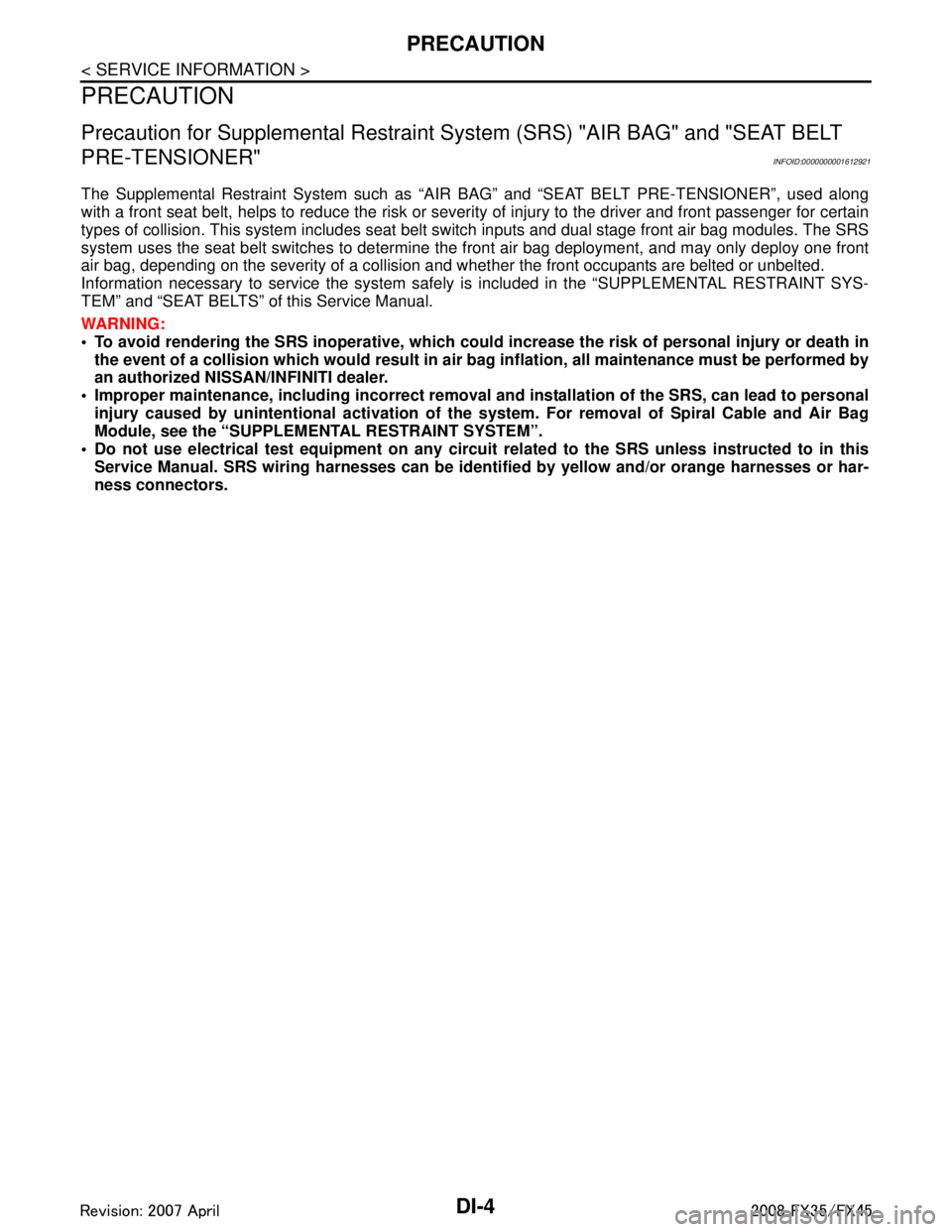
< SERVICE INFORMATION >
PRECAUTION
PRECAUTION
Precaution for Supplemental Restraint System (SRS) "AIR BAG" and "SEAT BELT
PRE-TENSIONER"
INFOID:0000000001612921
The Supplemental Restraint System such as “A IR BAG” and “SEAT BELT PRE-TENSIONER”, used along
with a front seat belt, helps to reduce the risk or severi ty of injury to the driver and front passenger for certain
types of collision. This system includes seat belt switch inputs and dual stage front air bag modules. The SRS
system uses the seat belt switches to determine the front air bag deployment, and may only deploy one front
air bag, depending on the severity of a collision and w hether the front occupants are belted or unbelted.
Information necessary to service the system safely is included in the “SUPPLEMENTAL RESTRAINT SYS-
TEM” and “SEAT BELTS” of this Service Manual.
WARNING:
• To avoid rendering the SRS inopera tive, which could increase the risk of personal injury or death in
the event of a collision which would result in air bag inflation, all maintenance must be performed by
an authorized NISS AN/INFINITI dealer.
Improper maintenance, including in correct removal and installation of the SRS, can lead to personal
injury caused by unintent ional activation of the system. For re moval of Spiral Cable and Air Bag
Module, see the “SUPPLEMEN TAL RESTRAINT SYSTEM”.
Do not use electrical test equipmen t on any circuit related to the SRS unless instructed to in this
Service Manual. SRS wiring harnesses can be identi fied by yellow and/or orange harnesses or har-
ness connectors.
3AA93ABC3ACD3AC03ACA3AC03AC63AC53A913A773A893A873A873A8E3A773A983AC73AC93AC03AC3
3A893A873A873A8F3A773A9D3AAF3A8A3A8C3A863A9D3AAF3A8B3A8C
Page 1152 of 3924

DI-26
< SERVICE INFORMATION >
UNIFIED METER AND A/C AMP
UNIFIED METER AND A/C AMP
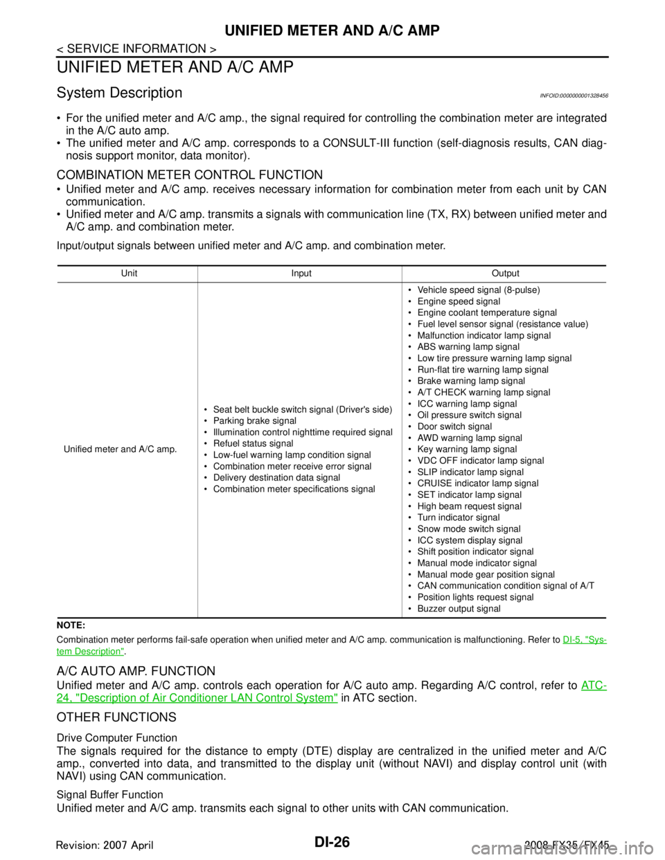
System DescriptionINFOID:0000000001328456
For the unified meter and A/C amp., the signal required for controlling the combination meter are integrated
in the A/C auto amp.
The unified meter and A/C amp. corresponds to a CONS ULT-III function (self-diagnosis results, CAN diag-
nosis support monitor, data monitor).
COMBINATION METER CONTROL FUNCTION
Unified meter and A/C amp. receives necessary information for combination meter from each unit by CAN communication.
Unified meter and A/C amp. transmits a signals with communication line (TX, RX) between unified meter and A/C amp. and combination meter.
Input/output signals between unified meter and A/C amp. and combination meter.
NOTE:
Combination meter performs fail-safe operation when unified meter and A/C amp. communication is malfunctioning. Refer to DI-5, "
Sys-
tem Description".
A/C AUTO AMP. FUNCTION
Unified meter and A/C amp. controls each operation for A/C auto amp. Regarding A/C control, refer to AT C -
24, "Description of Air Conditioner LAN Control System" in ATC section.
OTHER FUNCTIONS
Drive Computer Function
The signals required for the distance to empty (DTE) display are centralized in the unified meter and A/C
amp., converted into data, and transmitted to the disp lay unit (without NAVI) and display control unit (with
NAVI) using CAN communication.
Signal Buffer Function
Unified meter and A/C amp. transmits each signal to other units with CAN communication.
Unit Input Output
Unified meter and A/C amp. Seat belt buckle switch signal (Driver's side)
Parking brake signal
Illumination control nighttime required signal
Refuel status signal
Low-fuel warning lamp condition signal
Combination meter receive error signal
Delivery destination data signal
Combination meter specifications signal Vehicle speed signal (8-pulse)
Engine speed signal
Engine coolant temperature signal
Fuel level sensor signal (resistance value)
Malfunction indicator lamp signal
ABS warning lamp signal
Low tire pressure warning lamp signal
Run-flat tire wa
rning lamp signal
Brake warning lamp signal
A/T CHECK warning lamp signal
ICC warning lamp signal
Oil pressure switch signal
Door switch signal
AWD warning lamp signal
Key warning lamp signal
VDC OFF indicator lamp signal
SLIP indicator lamp signal
CRUISE indicator lamp signal
SET indicator lamp signal
High beam request signal
Turn indicator signal
Snow mode switch signal
ICC system display signal
Shift position indicator signal
Manual mode indicator signal
Manual mode gear position signal
CAN communication condition signal of A/T
Position lights request signal
Buzzer output signal
3AA93ABC3ACD3AC03ACA3AC03AC63AC53A913A773A893A873A873A8E3A773A983AC73AC93AC03AC3
3A893A873A873A8F3A773A9D3AAF3A8A3A8C3A863A9D3AAF3A8B3A8C
Page 1154 of 3924

DI-28
< SERVICE INFORMATION >
UNIFIED METER AND A/C AMP
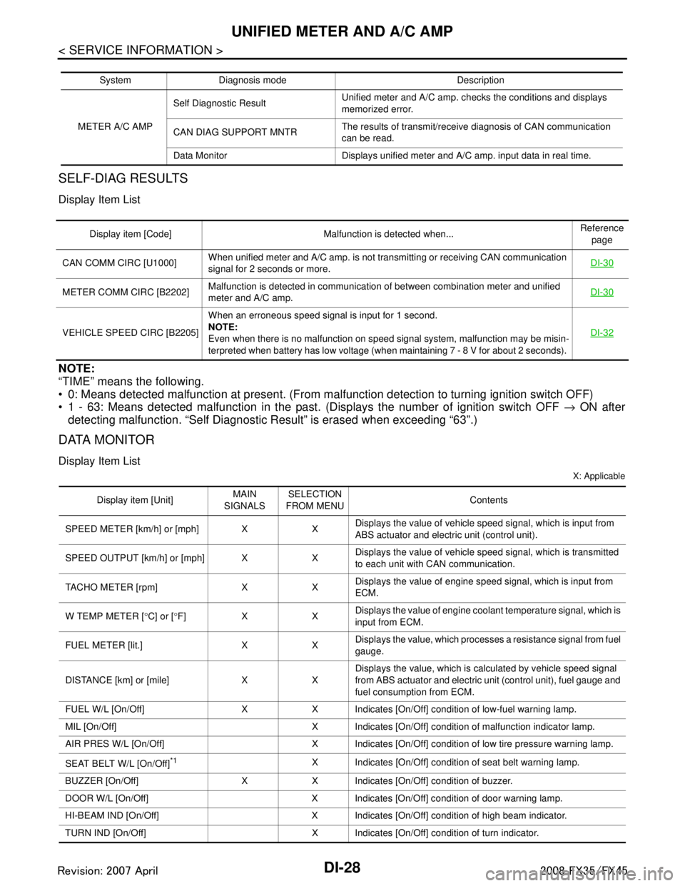
SELF-DIAG RESULTS
Display Item List
NOTE:
“TIME” means the following.
0: Means detected malfunction at present. (From malfunction detection to turning ignition switch OFF)
1 - 63: Means detected malfunction in the past . (Displays the number of ignition switch OFF → ON after
detecting malfunction. “Self Diagnostic Result” is erased when exceeding “63”.)
DATA MONITOR
Display Item List
X: Applicable
System Diagnosis mode Description
METER A/C AMP Self Diagnostic Result
Unified meter and A/C amp. checks the conditions and displays
memorized error.
CAN DIAG SUPPORT MNTR The results of transmit/receive diagnosis of CAN communication
can be read.
Data Monitor Displays unified meter and A/C amp. input data in real time.
Display item [Code] Malfunction is detected when... Reference
page
CAN COMM CIRC [U1000] When unified meter and A/C amp. is not transmitting or receiving CAN communication
signal for 2 seconds or more. DI-30
METER COMM CIRC [B2202]Malfunction is detected in communication of between combination meter and unified
meter and A/C amp.
DI-30
VEHICLE SPEED CIRC [B2205]When an erroneous speed signal is input for 1 second.
NOTE:
Even when there is no malfunction on speed signal system, malfunction may be misin-
terpreted when battery has low voltage (when maintaining 7 - 8 V for about 2 seconds). DI-32
Display item [Unit]
MAIN
SIGNALS SELECTION
FROM MENU Contents
SPEED METER [km/h] or [mph] X X Displays the value of vehicle speed signal, which is input from
ABS actuator and electric unit (control unit).
SPEED OUTPUT [km/h] or [mph] X X Displays the value of vehicle speed signal, which is transmitted
to each unit with CAN communication.
TACHO METER [rpm] X X Displays the value of engine speed signal, which is input from
ECM.
W TEMP METER [ °C] or [ °F] X X Displays the value of engine coolant temperature signal, which is
input from ECM.
FUEL METER [lit.] X X Displays the value, which processes a resistance signal from fuel
gauge.
DISTANCE [km] or [mile] X X Displays the value, which is calculated by vehicle speed signal
from ABS actuator and electric unit
(control unit), fuel gauge and
fuel consumption from ECM.
FUEL W/L [On/Off] X X Indicates [On/Off] condition of low-fuel warning lamp.
MIL [On/Off] X Indicates [On/Off] condition of malfunction indicator lamp.
AIR PRES W/L [On/Off] X Indicates [On/Off] condition of low tire pressure warning lamp.
SEAT BELT W/L [On/Off]
*1X Indicates [On/Off] condition of seat belt warning lamp.
BUZZER [On/Off] X X Indicates [On/Off] condition of buzzer.
DOOR W/L [On/Off] X Indicates [On/Off] condition of door warning lamp.
HI-BEAM IND [On/Off] X Indicates [On/Off] condition of high beam indicator.
TURN IND [On/Off] X Indicates [On/Off] condition of turn indicator.
3AA93ABC3ACD3AC03ACA3AC03AC63AC53A913A773A893A873A873A8E3A773A983AC73AC93AC03AC3
3A893A873A873A8F3A773A9D3AAF3A8A3A8C3A863A9D3AAF3A8B3A8C