Page 3626 of 3924
STARTING SYSTEMSC-17
< SERVICE INFORMATION >
C
DE
F
G H
I
J
L
M A
B
SC
N
O P
VQ35DE ENGINE MODELS (AWD) (S114-881A)
1. Magnetic switch assembly 2. Dust cover kit 3. Shift lever set
4. Center bracket (A) 5. Yoke assembly 6. Armature assembly
7. Brush holder assembly 8. Thrust washer 9. Rear cover assembly
10. Shaft gear assembly 11. Packing 12. Thrust washer
13. Center bracket (P) 14. E-ring 15. Pinion assembly
16. Ball bearing 17. Caul 18. Gear case assembly (H): High-temperatu re grease point
PKID0694E
3AA93ABC3ACD3AC03ACA3AC03AC63AC53A913A773A893A873A873A8E3A773A983AC73AC93AC03AC3
3A893A873A873A8F3A773A9D3AAF3A8A3A8C3A863A9D3AAF3A8B3A8C
Page 3627 of 3924
SC-18
< SERVICE INFORMATION >
STARTING SYSTEM
Inspection After Disassembly
INFOID:0000000001328253
PINION/CLUTCH CHECK
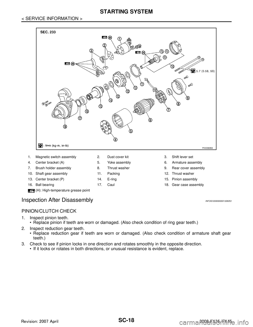
1. Inspect pinion teeth. Replace pinion if teeth are worn or damaged. (Also check condition of ring gear teeth.)
2. Inspect reduction gear teeth. Replace reduction gear if teeth are worn or dam aged. (Also check condition of armature shaft gear
teeth.)
3. Check to see if pinion locks in one directi on and rotates smoothly in the opposite direction.
If it locks or rotates in both directions , or unusual resistance is evident, replace.
1. Magnetic switch assembly 2. Dust cover kit 3. Shift lever set
4. Center bracket (A) 5. Yoke assembly 6. Armature assembly
7. Brush holder assembly 8. Thrust washer 9. Rear cover assembly
10. Shaft gear assembly 11. Packing 12. Thrust washer
13. Center bracket (P) 14. E-ring 15. Pinion assembly
16. Ball bearing 17. Caul 18. Gear case assembly
(H): High-temperatu re grease point
PKID0695E
3AA93ABC3ACD3AC03ACA3AC03AC63AC53A913A773A893A873A873A8E3A773A983AC73AC93AC03AC3
3A893A873A873A8F3A773A9D3AAF3A8A3A8C3A863A9D3AAF3A8B3A8C
Page 3639 of 3924

SC-30
< SERVICE INFORMATION >
SERVICE DATA AND SPECIFICATIONS (SDS)
SERVICE DATA AND SPECIFICATIONS (SDS)
BatteryINFOID:0000000001328260
StarterINFOID:0000000001328261
AlternatorINFOID:0000000001328262
Typ e11 0 D 2 6 L
Capacity V - AH 12 - 75
Cold cranking current (F or reference value) A 720
Applied model VK45DE VQ3 5DE (2WD) VQ35DE (AWD)
Ty p e M002T85075 S114-880A S114-881A
MITSUBISHI make HITACHI make Reduction gear type
System voltage V 12
No-load Te r m i n a l v o l t a g e V 11
Current A Less than 145 Less than 90
Revolution rpm More than 3,300 More than 2,880
Minimum diameter of commutator mm (in) 31.4 (1.236) 28.0 (1.102)
Minimum length of brush mm (in) 11.0 (0.433) 10.5 (0.413)
Brush spring tension N (kg, lb) 26.7 - 36.1
(2.72 - 3.68,
6.80 - 8.12) 16.2 (1.65, 3.6)
Clearance between bearing metal and armature shaft mm (in) Less than 0.2 (0.008)
Clearance between pinion front edge and pinion stopper mm (in) 0.5 - 2.0
(0.020 - 0.079) —
Movement in height of pinion assembly mm (in) — 0.3 - 2.5 (0.012 - 0.098)
Applied model VK45DE VQ35DE
Ty p e LR1110 - 716B A3TG0191
HITACHI make MITSUBISHI make
Nominal rating V - A 12 - 110
Ground polarity Negative
Minimum revolution under no-load (When 13.5 V is applied) rpm Less than 1,100 Less than 1,000
Hot output current (When 13.5 V is applied) A/rpm More than 70/1,800
More than 91/2,500
More than 110/5,000 More than 37/1,300
More than 92/2,500
More than 103/5,000
Regulated output voltage V 14.1 - 14.7
Minimum length of brush mm (in) More than 6.00 (0.236) More than 5.00 (0.197)
Brush spring pressure N (g, oz) 1.00 - 3.43
(102 - 350, 3.60 - 12.34) 4.8 - 6.0
(490 - 612, 17.28 - 21.60)
Slip ring minimum outer diameter mm (in) More than 26.0 (1.024) More than 22.1 (0.870)
Rotor (Field coil) resistance Ω2.31 1.7 - 2.1
3AA93ABC3ACD3AC03ACA3AC03AC63AC53A913A773A893A873A873A8E3A773A983AC73AC93AC03AC3
3A893A873A873A8F3A773A9D3AAF3A8A3A8C3A863A9D3AAF3A8B3A8C
Page 3648 of 3924
SQUEAK AND RATTLE TROUBLE DIAGNOSESSE-9
< SERVICE INFORMATION >
C
DE
F
G H
J
K L
M A
B
SE
N
O P
Most of these incidents can be repaired by adjusting, se curing or insulating the item(s) or component(s) caus-
ing the noise.
SUNROOF/HEADLINING
Noises in the sunroof/headlining area can often be traced to one of the following:
1. Sunroof lid, rail, linkage or seals making a rattle or light knocking noise
2. Sun-visor shaft shaking in the holder
3. Front or rear windshield touching headlining and squeaking
Again, pressing on the components to stop the noise while duplicating the conditions can isolate most of these
incidents. Repairs usually consist of insulating with felt cloth tape.
SEATS
When isolating seat noise it's important to note the pos ition the seat is in and the load placed on the seat when
the noise is present. These conditions should be duplic ated when verifying and isolating the cause of the
noise.
Cause of seat noise include:
1. Headrest rods and holder
2. A squeak between the seat pad cushion and frame
3. The rear seatback lock and bracket
These noises can be isolated by moving or pressing on the suspected components while duplicating the con-
ditions under which the noise occurs. Most of thes e incidents can be repaired by repositioning the component
or applying urethane tape to the contact area.
UNDERHOOD
Some interior noise may be caused by components under the hood or on the engine wall. The noise is then
transmitted into the passenger compartment.
Causes of transmitted under-hood noise include:
1. Any component mounted to the engine wall
2. Components that pass through the engine wall
3. Engine wall mounts and connectors
4. Loose radiator mounting pins
5. Hood bumpers out of adjustment
6. Hood striker out of adjustment
These noises can be difficult to isolate since they cannot be reached from the interior of the vehicle. The best
method is to secure, move or insulate one component at a time and test drive the vehicle. Also, engine RPM
or load can be changed to isolate the noise. Repairs c an usually be made by moving, adjusting, securing, or
insulating the component causing the noise.
3AA93ABC3ACD3AC03ACA3AC03AC63AC53A913A773A893A873A873A8E3A773A983AC73AC93AC03AC3
3A893A873A873A8F3A773A9D3AAF3A8A3A8C3A863A9D3AAF3A8B3A8C
Page 3747 of 3924
SRS-10
< SERVICE INFORMATION >
SUPPLEMENTAL RESTRAINT SYSTEM (SRS)
Front Seat Belt Pre-te nsioner with Load Limiter
INFOID:0000000001524155
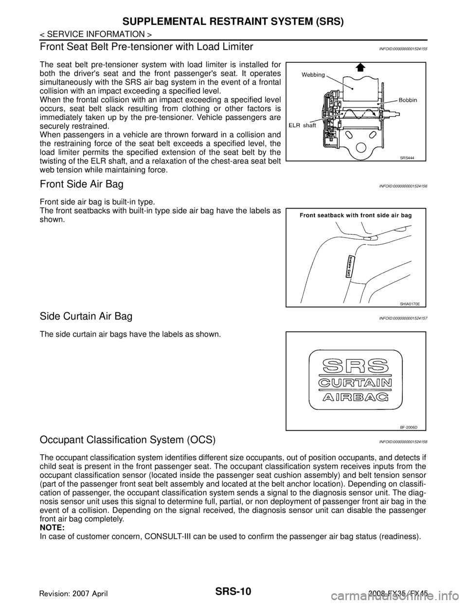
The seat belt pre-tensioner system wi th load limiter is installed for
both the driver's seat and the front passenger's seat. It operates
simultaneously with the SRS air bag system in the event of a frontal
collision with an impact exceeding a specified level.
When the frontal collision with an impact exceeding a specified level
occurs, seat belt slack resulting from clothing or other factors is
immediately taken up by the pre-tensioner. Vehicle passengers are
securely restrained.
When passengers in a vehicle are thrown forward in a collision and
the restraining force of the seat belt exceeds a specified level, the
load limiter permits the specified extension of the seat belt by the
twisting of the ELR shaft, and a relaxation of the chest-area seat belt
web tension while maintaining force.
Front Side Air BagINFOID:0000000001524156
Front side air bag is built-in type.
The front seatbacks with built-in type side air bag have the labels as
shown.
Side Curtain Air BagINFOID:0000000001524157
The side curtain air bags have the labels as shown.
Occupant Classification System (OCS)INFOID:0000000001524158
The occupant classification system identifies different si ze occupants, out of position occupants, and detects if
child seat is present in the front passenger seat. The oc cupant classification system receives inputs from the
occupant classification sensor (located inside the pa ssenger seat cushion assembly) and belt tension sensor
(part of the passenger front seat belt assembly and located at the belt anchor location). Depending on classifi-
cation of passenger, the occupant clas sification system sends a signal to the diagnosis sensor unit. The diag-
nosis sensor unit uses this signal to determine full, pa rtial, or non deployment of passenger front air bag in the
event of a collision. Depending on the signal received, the diagnosis sensor unit can disable the passenger
front air bag completely.
NOTE:
In case of customer concern, CONSULT-III can be used to confirm the passenger air bag status (readiness).
SRS444
SHIA0170E
BF-2006D
3AA93ABC3ACD3AC03ACA3AC03AC63AC53A913A773A893A873A873A8E3A773A983AC73AC93AC03AC3
3A893A873A873A8F3A773A9D3AAF3A8A3A8C3A863A9D3AAF3A8B3A8C
Page 3792 of 3924
TF-6
< SERVICE INFORMATION >
PREPARATION
PREPARATION
Special Service ToolINFOID:0000000001327426
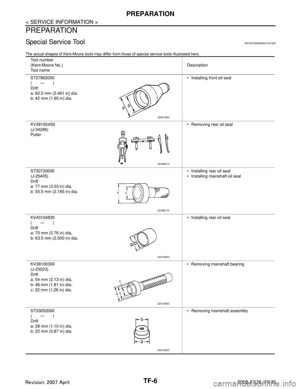
The actual shapes of Kent-Moore tools may differ from those of special service tools illustrated here.
Tool number
(Kent-Moore No.)
Tool name Description
ST27862000
(—)
Drift
a: 62.5 mm (2.461 in) dia.
b: 42 mm (1.65 in) dia. Installing front oil seal
KV381054S0
(J-34286)
Puller Removing rear oil seal
ST30720000
(J-25405)
Drift
a: 77 mm (3.03 in) dia.
b: 55.5 mm (2.185 in) dia. Installing rear oil seal
Installing mainshaft oil seal
KV40104830
(—)
Drift
a: 70 mm (2.76 in) dia.
b: 63.5 mm (2.500 in) dia. Installing rear oil seal
KV38100300
(J-25523)
Drift
a: 54 mm (2.13 in) dia.
b: 46 mm (1.81 in) dia.
c: 32 mm (1.26 in) dia. Removing mainshaft bearing
ST33052000
(—)
Drift
a: 28 mm (1.10 in) dia.
b: 22 mm (0.87 in) dia. Removing mainshaft assembly
ZZA0194D
ZZA0601D
ZZA0811D
ZZA1003D
ZZA1046D
ZZA1000D
3AA93ABC3ACD3AC03ACA3AC03AC63AC53A913A773A893A873A873A8E3A773A983AC73AC93AC03AC3
3A893A873A873A8F3A773A9D3AAF3A8A3A8C3A863A9D3AAF3A8B3A8C
Page 3793 of 3924
PREPARATIONTF-7
< SERVICE INFORMATION >
CEF
G H
I
J
K L
M A
B
TF
N
O P
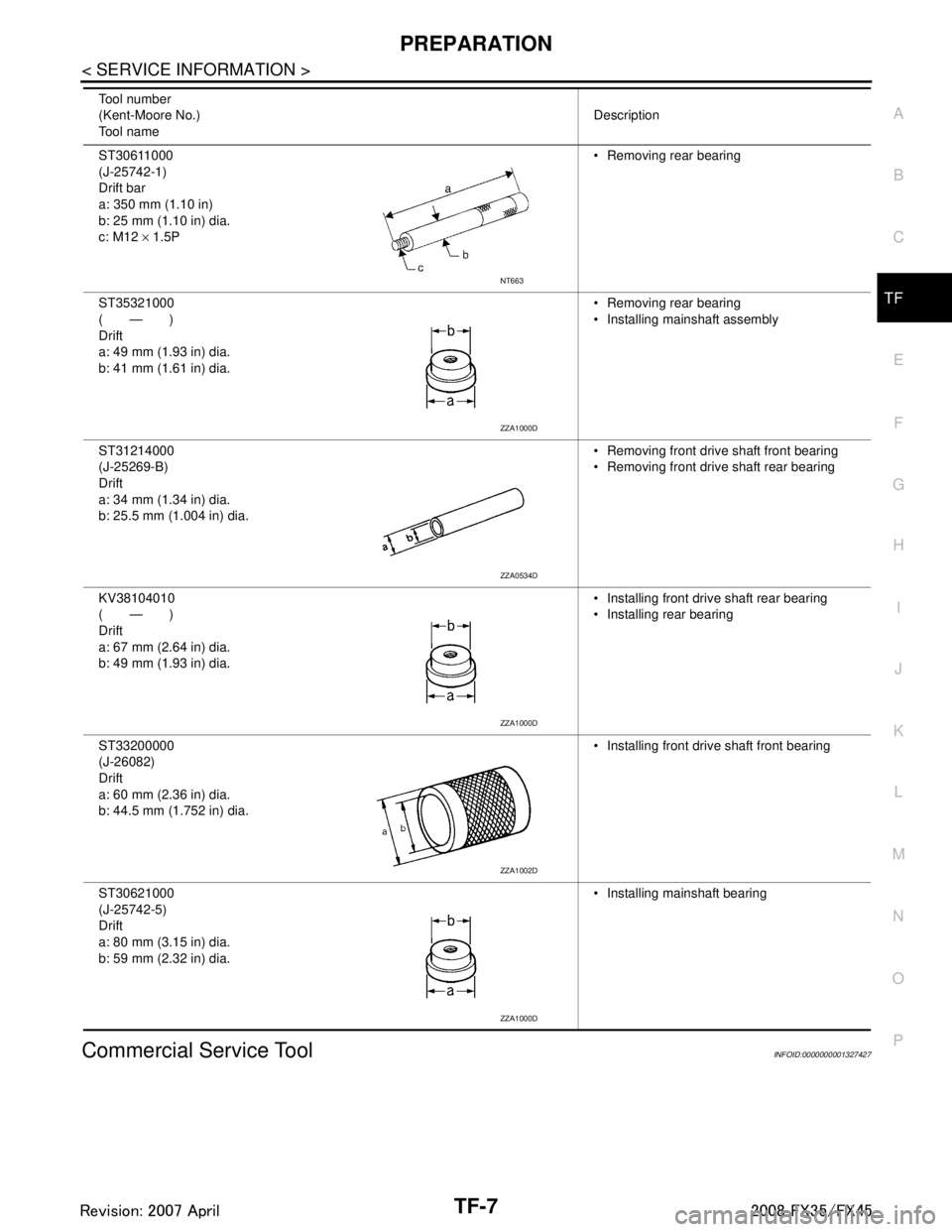
Commercial Service ToolINFOID:0000000001327427
ST30611000
(J-25742-1)
Drift bar
a: 350 mm (1.10 in)
b: 25 mm (1.10 in) dia.
c: M12 × 1.5P Removing rear bearing
ST35321000
(—)
Drift
a: 49 mm (1.93 in) dia.
b: 41 mm (1.61 in) dia. Removing rear bearing
Installing mainshaft assembly
ST31214000
(J-25269-B)
Drift
a: 34 mm (1.34 in) dia.
b: 25.5 mm (1.004 in) dia. Removing front drive shaft front bearing
Removing front drive shaft rear bearing
KV38104010
(—)
Drift
a: 67 mm (2.64 in) dia.
b: 49 mm (1.93 in) dia. Installing front drive shaft rear bearing
Installing rear bearing
ST33200000
(J-26082)
Drift
a: 60 mm (2.36 in) dia.
b: 44.5 mm (1.752 in) dia. Installing front drive shaft front bearing
ST30621000
(J-25742-5)
Drift
a: 80 mm (3.15 in) dia.
b: 59 mm (2.32 in) dia. Installing mainshaft bearing
Tool number
(Kent-Moore No.)
Tool name
Description
NT663
ZZA1000D
ZZA0534D
ZZA1000D
ZZA1002D
ZZA1000D
3AA93ABC3ACD3AC03ACA3AC03AC63AC53A913A773A893A873A873A8E3A773A983AC73AC93AC03AC3
3A893A873A873A8F3A773A9D3AAF3A8A3A8C3A863A9D3AAF3A8B3A8C
Page 3794 of 3924
TF-8
< SERVICE INFORMATION >
PREPARATION
Tool nameDescription
Puller Removing companion flange
Flange wrench Removing and installing self-lock nut
Puller Removing front drive shaft front bearing
Removing front drive shaft rear bearing
Power tool Loosening bolts and nuts
NT077
NT771
ZZB0823D
PBIC0190E
3AA93ABC3ACD3AC03ACA3AC03AC63AC53A913A773A893A873A873A8E3A773A983AC73AC93AC03AC3
3A893A873A873A8F3A773A9D3AAF3A8A3A8C3A863A9D3AAF3A8B3A8C