Page 3818 of 3924

TF-32
< SERVICE INFORMATION >
TROUBLE DIAGNOSIS FOR SYMPTOMS
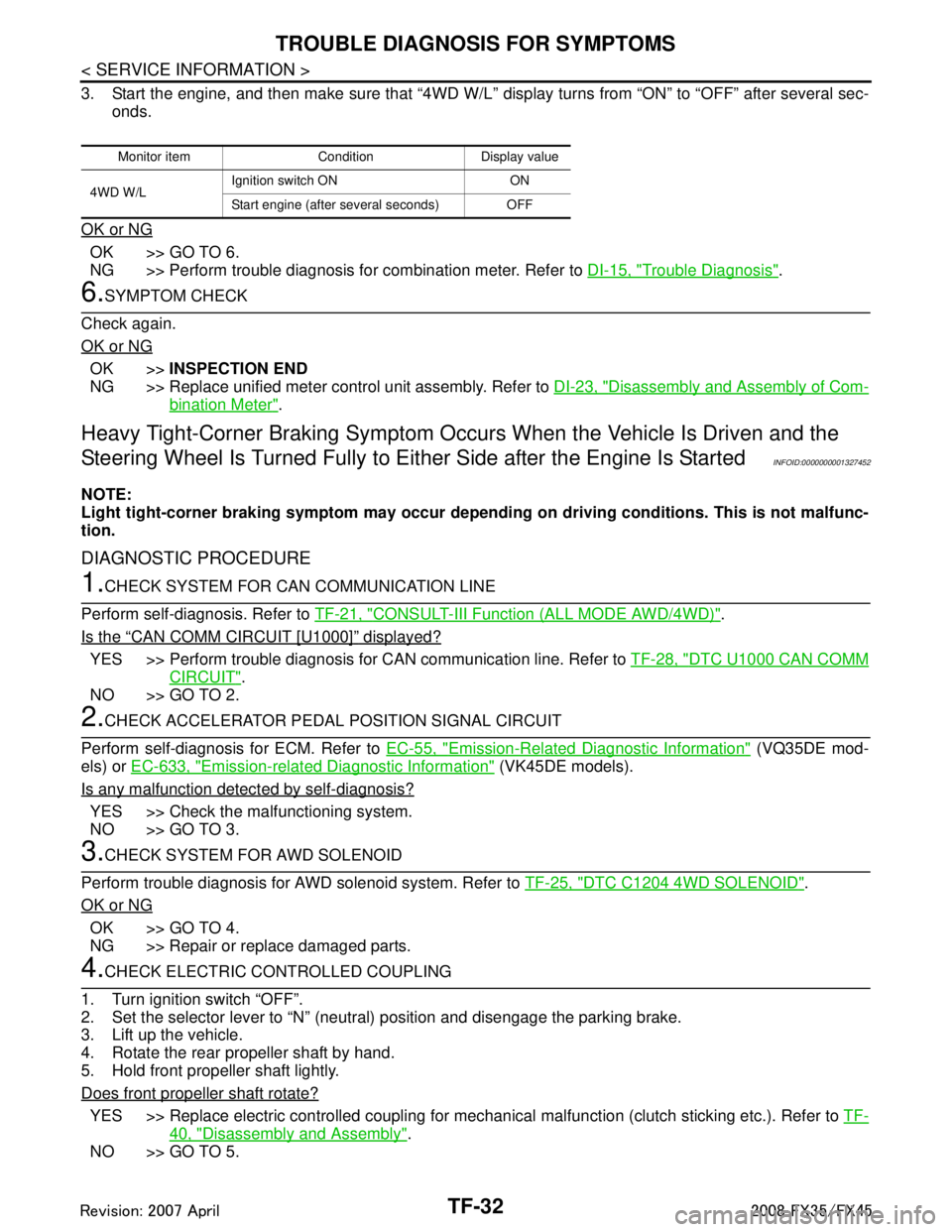
3. Start the engine, and then make sure that “4WD W/L” display turns from “ON” to “OFF” after several sec-
onds.
OK or NG
OK >> GO TO 6.
NG >> Perform trouble diagnosis for combination meter. Refer to DI-15, "
Trouble Diagnosis".
6.SYMPTOM CHECK
Check again.
OK or NG
OK >> INSPECTION END
NG >> Replace unified meter control unit assembly. Refer to DI-23, "
Disassembly and Assembly of Com-
bination Meter".
Heavy Tight-Corner Braking Symptom Occurs When the Vehicle Is Driven and the
Steering Wheel Is Turned Fu lly to Either Side after the Engine Is Started
INFOID:0000000001327452
NOTE:
Light tight-corner braking symptom may occur depending on driving conditions. This is not malfunc-
tion.
DIAGNOSTIC PROCEDURE
1.CHECK SYSTEM FOR CAN COMMUNICATION LINE
Perform self-diagnosis. Refer to TF-21, "
CONSULT-III Function (ALL MODE AWD/4WD)".
Is the
“CAN COMM CIRCUIT [U1000]” displayed?
YES >> Perform trouble diagnosis for CAN communication line. Refer to TF-28, "DTC U1000 CAN COMM
CIRCUIT".
NO >> GO TO 2.
2.CHECK ACCELERATOR PEDAL POSITION SIGNAL CIRCUIT
Perform self-diagnosis for ECM. Refer to EC-55, "
Emission-Related Diagnostic Information" (VQ35DE mod-
els) or EC-633, "
Emission-related Diagnostic Information" (VK45DE models).
Is any malfunction detec ted by self-diagnosis?
YES >> Check the malfunctioning system.
NO >> GO TO 3.
3.CHECK SYSTEM FOR AWD SOLENOID
Perform trouble diagnosis for AWD solenoid system. Refer to TF-25, "
DTC C1204 4WD SOLENOID".
OK or NG
OK >> GO TO 4.
NG >> Repair or replace damaged parts.
4.CHECK ELECTRIC CONTROLLED COUPLING
1. Turn ignition switch “OFF”.
2. Set the selector lever to “N” (neutral) position and disengage the parking brake.
3. Lift up the vehicle.
4. Rotate the rear propeller shaft by hand.
5. Hold front propeller shaft lightly.
Does front propeller shaft rotate?
YES >> Replace electric controlled coupling for mec hanical malfunction (clutch sticking etc.). Refer to TF-
40, "Disassembly and Assembly".
NO >> GO TO 5.
Monitor item Condition Display value
4WD W/L Ignition switch ON ON
Start engine (after several seconds) OFF
3AA93ABC3ACD3AC03ACA3AC03AC63AC53A913A773A893A873A873A8E3A773A983AC73AC93AC03AC3
3A893A873A873A8F3A773A9D3AAF3A8A3A8C3A863A9D3AAF3A8B3A8C
Page 3822 of 3924
TF-36
< SERVICE INFORMATION >
FRONT OIL SEAL
FRONT OIL SEAL
Removal and InstallationINFOID:0000000001327457
REMOVAL
1. Remove the drain plug to drain the transfer fluid. Refer to TF-10, "Replacement".
2. Remove the front propeller shaft. Refer to PR-4
.
3. Remove front oil seal using a flat-bladed screwdriver. CAUTION:
Be careful not to damage the front case and front drive
shaft.
INSTALLATION
1. Apply ATF to front oil seal, install it with a drift until the end faceof front case.
CAUTION:
Do not reuse front oil seal.
When installing, do no t incline front oil seal.
2. Install front propeller shaft. Refer to PR-4
.
3. Install transfer fluid, check fluid level and for fluid leakage. Refer to TF-10, "
Inspection".
SDIA1782E
Tool number : ST27862000 ( — )
SDIA1783E
3AA93ABC3ACD3AC03ACA3AC03AC63AC53A913A773A893A873A873A8E3A773A983AC73AC93AC03AC3
3A893A873A873A8F3A773A9D3AAF3A8A3A8C3A863A9D3AAF3A8B3A8C
Page 3823 of 3924
REAR OIL SEALTF-37
< SERVICE INFORMATION >
CEF
G H
I
J
K L
M A
B
TF
N
O P
REAR OIL SEAL
Removal and InstallationINFOID:0000000001327458
REMOVAL
1. Remove the rear propeller shaft. Refer to PR-7.
2. Remove self-lock nut of companion flange using the flange wrench.
3. Put matching mark on the end of the mainshaft. The mark should be in line with the mark on the companion flange.
CAUTION:
For matching mark, use paint. Do not damage mainshaft.
4. Remove the companion flange using a puller. CAUTION:
Be careful not to damage the companion flange.
5. Remove the rear oil seal using a puller. CAUTION:
Be careful not to damage the rear case.
INSTALLATION
SDIA2454E
SDIA2378E
SDIA1785E
Tool number : KV381054S0 (J-34286)
SDIA1786E
3AA93ABC3ACD3AC03ACA3AC03AC63AC53A913A773A893A873A873A8E3A773A983AC73AC93AC03AC3
3A893A873A873A8F3A773A9D3AAF3A8A3A8C3A863A9D3AAF3A8B3A8C
Page 3824 of 3924
TF-38
< SERVICE INFORMATION >
REAR OIL SEAL
1. Apply ATF to rear oil seal, install it with a drift.CAUTION:
Do not reuse rear oil seal.
When installing, do not incline rear oil seal.
2. Align the matching mark of mainshaft with the mark of compan- ion flange, then install the companion flange.
3. Using flange wrench, install the self-lock nut of companion flange and tighten to the specified torque. Refer to TF-40, "
Dis-
assembly and Assembly".
CAUTION:
Do not reuse self-lock nut.
4. Install the rear propeller shaft. Refer to PR-7
.
5. Check fluid level. Refer to TF-10, "
Inspection".
Dimension A : 6.7 - 7.3 mm (0.264 - 0.287 in)
Tool number A: ST30720000 (J-25405)
B: KV40104830 ( — )
PDIA0292E
SDIA2378E
PDIA0245E
3AA93ABC3ACD3AC03ACA3AC03AC63AC53A913A773A893A873A873A8E3A773A983AC73AC93AC03AC3
3A893A873A873A8F3A773A9D3AAF3A8A3A8C3A863A9D3AAF3A8B3A8C
Page 3826 of 3924

TF-40
< SERVICE INFORMATION >
TRANSFER ASSEMBLY
TRANSFER ASSEMBLY
Removal and InstallationINFOID:0000000001327460
REMOVAL
1. Remove tunnel stay with power tool. Refer to RSU-6, "Removal and Installation".
2. Remove exhaust front tube with power tool. Refer to EX-3
.
3. Remove front and rear propeller shaft. Refer to PR-4
and PR-7.
4. Disconnect transfer assembly harness connector and separate harness from transfer assembly.
5. Remove air breather hose. Refer to TF-39
.
6. Support transfer assembly and transmission assembly with a jack.
7. Remove engine rear member with power tool. Refer to EM-112
(VQ35DE) or EM-237 (VK45DE).
8. Remove transfer mounting bolts and se parate transfer from transmission.
CAUTION:
Secure transfer assembly to a jack.
INSTALLATION
Note the following, and install in the reverse order of removal.
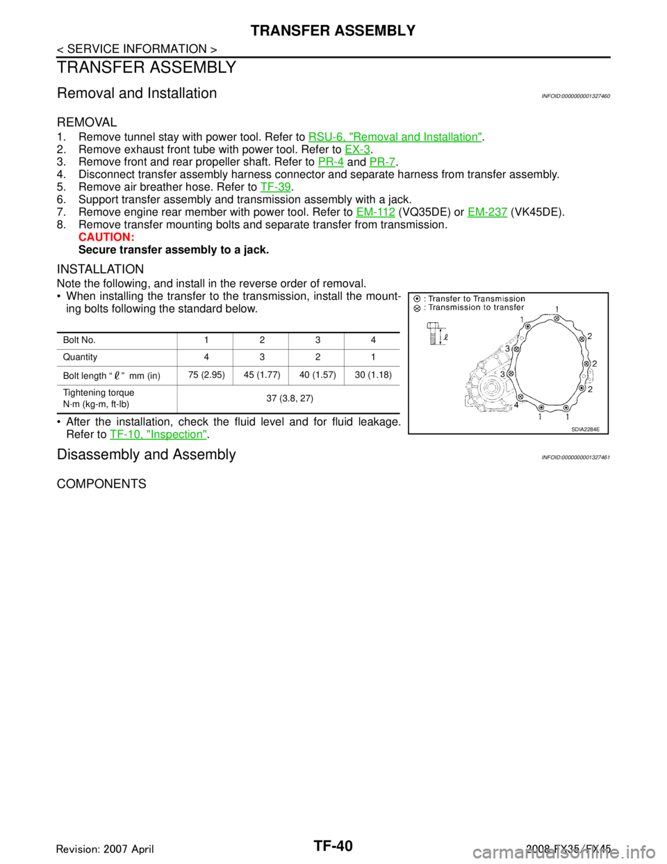
When installing the transfer to the transmission, install the mount-
ing bolts following the standard below.
After the installation, check the fluid level and for fluid leakage. Refer to TF-10, "
Inspection".
Disassembly and AssemblyINFOID:0000000001327461
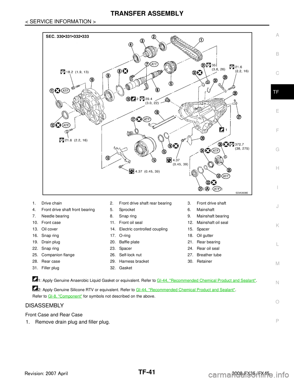
COMPONENTS
Bolt No. 1234
Quantity 4321
Bolt length “ ” mm (in) 75 (2.95) 45 (1.77) 40 (1.57) 30 (1.18)
Tightening torque
N·m (kg-m, ft-lb) 37 (3.8, 27)
SDIA2284E
3AA93ABC3ACD3AC03ACA3AC03AC63AC53A913A773A893A873A873A8E3A773A983AC73AC93AC03AC3
3A893A873A873A8F3A773A9D3AAF3A8A3A8C3A863A9D3AAF3A8B3A8C
Page 3827 of 3924

TRANSFER ASSEMBLYTF-41
< SERVICE INFORMATION >
CEF
G H
I
J
K L
M A
B
TF
N
O P
DISASSEMBLY
Front Case and Rear Case
1. Remove drain plug and filler plug.
1. Drive chain 2. Front drive shaft rear bearing 3. Front drive shaft
4. Front drive shaft front bearing 5. Sprocket 6. Mainshaft
7. Needle bearing 8. Snap ring 9. Mainshaft bearing
10. Front case 11. Front oil seal 12. Mainshaft oil seal
13. Oil cover 14. Electric controlled coupling 15. Spacer
16. Snap ring 17. O-ring 18. Oil gutter
19. Drain plug 20. Baffle plate 21. Rear bearing
22. Snap ring 23. Spacer 24. Rear oil seal
25. Companion flange 26. Self-lock nut 27. Breather tube
28. Rear case 29. Harness bracket 30. Retainer
31. Filler plug 32. Gasket 1: Apply Genuine Anaerobic Liquid Gasket or equivalent. Refer to GI-44, "
Recommended Chemical Product and Sealant".
2: Apply Genuine Silicone RTV or equivalent. Refer to GI-44, "
Recommended Chemical Product and Sealant".
Refer to GI-8, "
Component" for symbols not described on the above.
SDIA3608E
3AA93ABC3ACD3AC03ACA3AC03AC63AC53A913A773A893A873A873A8E3A773A983AC73AC93AC03AC3
3A893A873A873A8F3A773A9D3AAF3A8A3A8C3A863A9D3AAF3A8B3A8C
Page 3828 of 3924
TF-42
< SERVICE INFORMATION >
TRANSFER ASSEMBLY
2. Remove mainshaft oil seal from front case, using a flat-bladedscrewdriver.
CAUTION:
Be careful not to damage the front case and mainshaft.
3. Remove front oil seal from front case, using a flat-bladed screw- driver.
CAUTION:
Be careful not to damage the front case and front drive
shaft.
4. Remove self-lock nut.
5. Put a matching mark on the end of mainshaft. The mark should be in line with the mark on the companion flange.
CAUTION:
For matching mark, use paint. Do not damage mainshaft.
6. Remove companion flange, using a puller. CAUTION:
Be careful not to damage the companion flange.
PDIA0253E
PDIA0255E
SDIA2378E
PDIA0258E
3AA93ABC3ACD3AC03ACA3AC03AC63AC53A913A773A893A873A873A8E3A773A983AC73AC93AC03AC3
3A893A873A873A8F3A773A9D3AAF3A8A3A8C3A863A9D3AAF3A8B3A8C
Page 3829 of 3924
TRANSFER ASSEMBLYTF-43
< SERVICE INFORMATION >
CEF
G H
I
J
K L
M A
B
TF
N
O P
7. Remove rear oil seal from rear case, using a puller.
CAUTION:
Be careful not to damage the rear case.
8. Remove spacer from mainshaft.
9. Remove front case and rear case fixing bolts, then remove har- ness bracket.
10. Separate front case and rear case. Then, remove front case by levering it up with a tire lever or the like.
CAUTION:
Be careful not to damage the mating surface.Tool number : KV381054S0 (J-34286)
PDIA0259E
PDIA0260E
Bolts symbol Quantity
Bolt length “ ” mm (in)
A 11 42 (1.65)
B 1 162 (6.38)
C197 (3.82)
TORX bolts 1 40 (1.57)
PDIA0251E
SDIA2460E
3AA93ABC3ACD3AC03ACA3AC03AC63AC53A913A773A893A873A873A8E3A773A983AC73AC93AC03AC3
3A893A873A873A8F3A773A9D3AAF3A8A3A8C3A863A9D3AAF3A8B3A8C