Page 3490 of 3924
POWER STEERING OIL PUMPPS-35
< SERVICE INFORMATION >
C
DE
F
H I
J
K L
M A
B
PS
N
O P
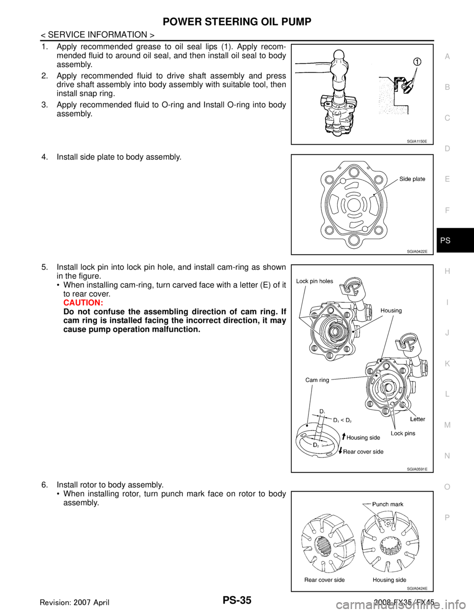
1. Apply recommended grease to oil seal lips (1). Apply recom- mended fluid to around oil seal, and then install oil seal to body
assembly.
2. Apply recommended fluid to drive shaft assembly and press drive shaft assembly into body assembly with suitable tool, then
install snap ring.
3. Apply recommended fluid to O-ring and Install O-ring into body assembly.
4. Install side plate to body assembly.
5. Install lock pin into lock pin hole, and install cam-ring as shown in the figure.
When installing cam-ring, turn carved face with a letter (E) of itto rear cover.
CAUTION:
Do not confuse the assembling direction of cam ring. If
cam ring is installed facing th e incorrect direction, it may
cause pump operation malfunction.
6. Install rotor to body assembly. When installing rotor, turn punch mark face on rotor to bodyassembly.
SGIA1150E
SGIA0422E
SGIA0591E
SGIA0424E
3AA93ABC3ACD3AC03ACA3AC03AC63AC53A913A773A893A873A873A8E3A773A983AC73AC93AC03AC3
3A893A873A873A8F3A773A9D3AAF3A8A3A8C3A863A9D3AAF3A8B3A8C
Page 3491 of 3924
PS-36
< SERVICE INFORMATION >
POWER STEERING OIL PUMP
7. Install vane to rotor with facing the round portion outside.
8. Check if drive shaft assembly turns smoothly.
9. Install gasket to body assembly.
10. Install rear cover to body assembly and tighten bolts at the spec-ified torque.
11. Install bracket to rear cover and tighten bolts at the specified torque.
12. Install pulley to drive shaft assembly then tighten lock nut at the specified torque.
13. Install spring, flow control valve, O-ring, connector bolt, joint, washer to body assembly. Then tighten lock nut at the specified
torque.
14. Apply recommended fluid to O-ring and Install O-ring to suction pipe.
15. Install suction pipe to body assembly.
SST843A
SGIA0425E
3AA93ABC3ACD3AC03ACA3AC03AC63AC53A913A773A893A873A873A8E3A773A983AC73AC93AC03AC3
3A893A873A873A8F3A773A9D3AAF3A8A3A8C3A863A9D3AAF3A8B3A8C
Page 3499 of 3924
RAX-1
DRIVELINE/AXLE
CEF
G H
I
J
K L
M
SECTION RAX
A
B
RAX
N
O P
CONTENTS
REAR AXLE
SERVICE INFORMATION .. ..........................2
PRECAUTIONS .............................................. .....2
Caution ................................................................ ......2
PREPARATION ...................................................3
Special Service Tool ........................................... ......3
Commercial Service Tool ..........................................4
NOISE, VIBRATION AND HARSHNESS
(NVH) TROUBLESHOOTING .............................
5
NVH Troubleshooting Chart ................................ ......5
REAR WHEEL HUB AND KNUCKLE ...............6
On-Vehicle Inspection ......................................... .....6
Removal and Installation ..........................................6
Disassembly and Assembly ......................................7
REAR DRIVE SHAFT ........................................10
Removal and Installation .........................................10
Disassembly and Assembly .....................................10
SERVICE DATA AND SPECIFICATIONS
(SDS) .................................................................
17
Wheel Bearing .........................................................17
Drive Shaft ...............................................................17
3AA93ABC3ACD3AC03ACA3AC03AC63AC53A913A773A893A873A873A8E3A773A983AC73AC93AC03AC3
3A893A873A873A8F3A773A9D3AAF3A8A3A8C3A863A9D3AAF3A8B3A8C
Page 3500 of 3924
RAX-2
< SERVICE INFORMATION >
PRECAUTIONS
SERVICE INFORMATION
PRECAUTIONS
CautionINFOID:0000000001327522
Observe the following precautions when disassembling and servicing drive shaft.
• Perform work in a location which is as dust-free as possible.
Before disassembling and servicing, clean the outside of parts.
Prevention of the entry of foreign objects must be taken into account during disassembly of the service loca-
tion.
Disassembled parts must be carefully reassembled in t he correct order. If work is interrupted, a clean cover
must be placed over parts.
Paper shop cloths must be used. Fabric shop cloths must not be used because of the danger of lint adhering
to parts.
Disassembled parts (except for rubber parts) should be cleaned with kerosene which shall be removed by
blowing with air or wiping with paper shop cloths.
3AA93ABC3ACD3AC03ACA3AC03AC63AC53A913A773A893A873A873A8E3A773A983AC73AC93AC03AC3
3A893A873A873A8F3A773A9D3AAF3A8A3A8C3A863A9D3AAF3A8B3A8C
Page 3501 of 3924
PREPARATIONRAX-3
< SERVICE INFORMATION >
CEF
G H
I
J
K L
M A
B
RAX
N
O P
PREPARATION
Special Service ToolINFOID:0000000001327523
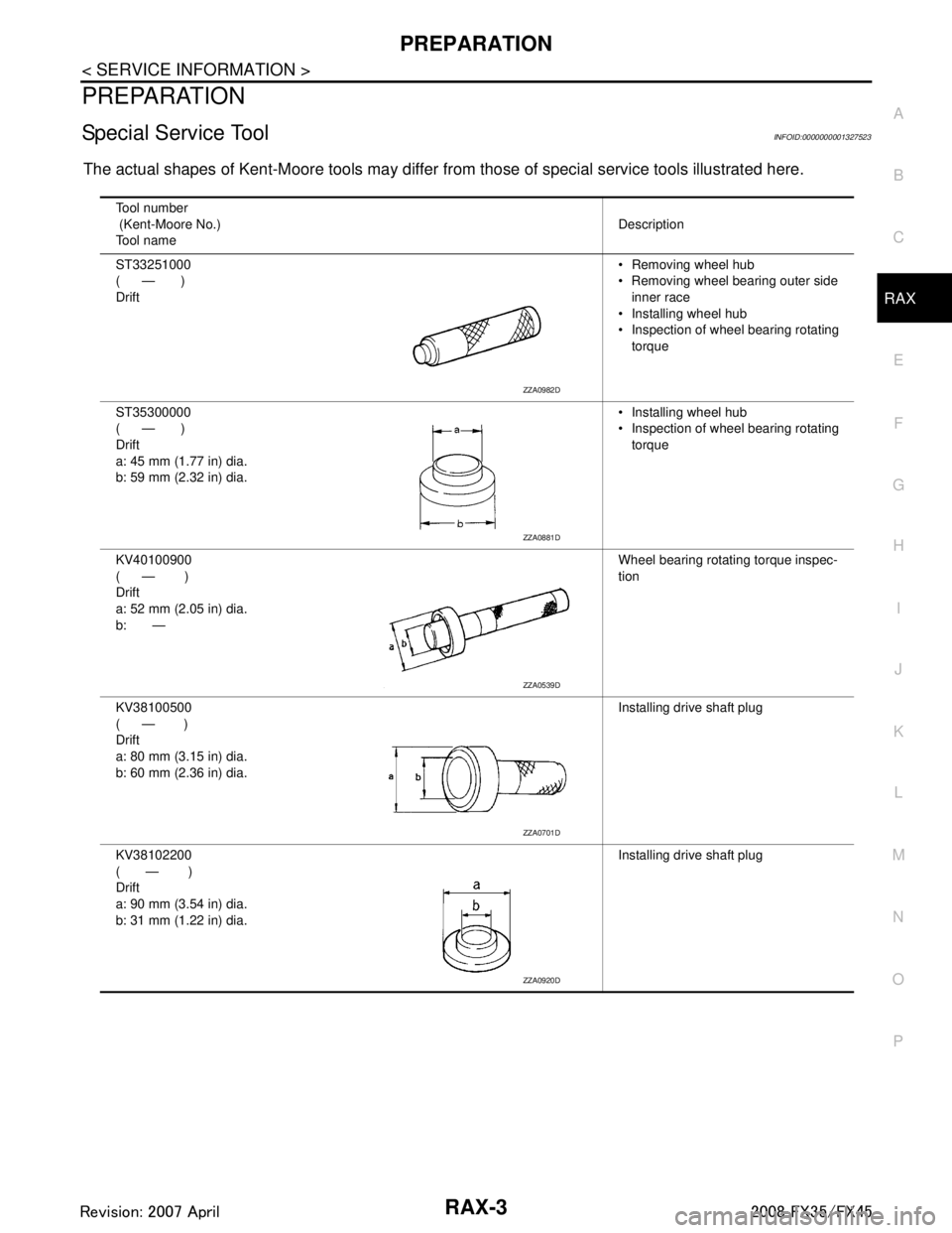
The actual shapes of Kent-Moore tools may differ fr om those of special service tools illustrated here.
Tool number
(Kent-Moore No.)
Tool name Description
ST33251000
( — )
Drift Removing wheel hub
Removing wheel bearing outer side
inner race
Installing wheel hub
Inspection of wheel bearing rotating torque
ST35300000
( — )
Drift
a: 45 mm (1.77 in) dia.
b: 59 mm (2.32 in) dia. Installing wheel hub
Inspection of wheel bearing rotating
torque
KV40100900
( — )
Drift
a: 52 mm (2.05 in) dia.
b: — Wheel bearing rotating torque inspec-
tion
KV38100500
( — )
Drift
a: 80 mm (3.15 in) dia.
b: 60 mm (2.36 in) dia. Installing drive shaft plug
KV38102200
( — )
Drift
a: 90 mm (3.54 in) dia.
b: 31 mm (1.22 in) dia. Installing drive shaft plug
ZZA0982D
ZZA0881D
ZZA0539D
ZZA0701D
ZZA0920D
3AA93ABC3ACD3AC03ACA3AC03AC63AC53A913A773A893A873A873A8E3A773A983AC73AC93AC03AC3
3A893A873A873A8F3A773A9D3AAF3A8A3A8C3A863A9D3AAF3A8B3A8C
Page 3503 of 3924
NOISE, VIBRATION AND HARSHNESS (NVH) TROUBLESHOOTINGRAX-5
< SERVICE INFORMATION >
CEF
G H
I
J
K L
M A
B
RAX
N
O P
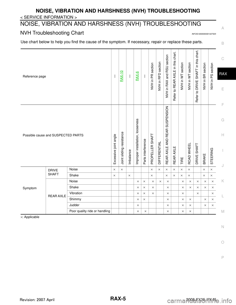
NOISE, VIBRATION AND HARSHN ESS (NVH) TROUBLESHOOTING
NVH Troubleshooting ChartINFOID:0000000001327525
Use chart below to help you find the cause of the symp tom. If necessary, repair or replace these parts.
×: ApplicableReference page
—
RAX-10—
RAX-6—
NVH in PR section
NVH in RFD section
NVH in RAX and RSU section
Refer to REAR AXLE in this chart. NVH in WT section
NVH in WT section
Refer to DRIVE SHAFT in this chart.
NVH in BR sectionNVH in PS section
Possible cause and SUSPECTED PARTS
Excessive joint angle
Joint sliding resistance
Imbalance
Improper installation, looseness
Parts interference
PROPELLER SHAFT
DIFFERENTIAL
REAR AXLE AND REAR SUSPENSION
REAR AXLE
TIRE
ROAD WHEEL
DRIVE SHAFT
BRAKE
STEERING
Symptom DRIVE
SHAFT
Noise
×× ×××××× ××
Shake × × × ×××× ××
REAR AXLE Noise
×× ××× ×××××
Shake ×× × × ×××××
Vibration ×××××××
Shimmy ×× × × × × ×
Judder × × ×× ××
Poor quality ride or handling ×× × ××
3AA93ABC3ACD3AC03ACA3AC03AC63AC53A913A773A893A873A873A8E3A773A983AC73AC93AC03AC3
3A893A873A873A8F3A773A9D3AAF3A8A3A8C3A863A9D3AAF3A8B3A8C
Page 3504 of 3924
RAX-6
< SERVICE INFORMATION >
REAR WHEEL HUB AND KNUCKLE
REAR WHEEL HUB AND KNUCKLE
On-Vehicle InspectionINFOID:0000000001327526
Make sure the mounting conditions (looseness, back lash) of each component and component status (wear,
damage) are normal.
WHEEL BEARING INSPECTION
With the vehicle raised, inspect the following.
Move wheel hub in the axial direction by hand. Che ck that there is no looseness of front wheel bearing.
Rotate wheel hub and make sure there is no unusual noi se or other irregular conditions. If there are any
irregular conditions, replace wheel hub and bearing assembly.
Removal and InstallationINFOID:0000000001327527
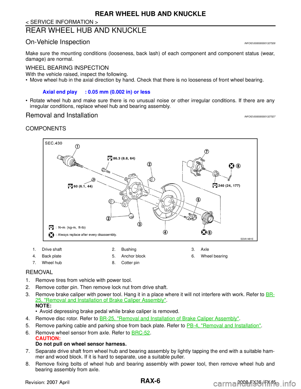
COMPONENTS
REMOVAL
1. Remove tires from vehicle with power tool.
2. Remove cotter pin. Then remove lock nut from drive shaft.
3. Remove brake caliper with power tool. Hang it in a place where it will not interfere with work. Refer to BR-
25, "Removal and Installation of Brake Caliper Assembly".
NOTE:
Avoid depressing brake pedal while brake caliper is removed.
4. Remove disc rotor. Refer to BR-25, "
Removal and Installation of Brake Caliper Assembly".
5. Remove parking cable and parking shoe from back plate. Refer to PB-4, "
Removal and Installation".
6. Remove wheel sensor from axle. Refer to BRC-52
.
CAUTION:
Do not pull on wheel sensor harness.
7. Separate drive shaft from wheel hub and bearing assembly by lightly tapping the end with a suitable ham- mer and wood block. If it is hard to separate, use a suitable puller.
8. Remove fixing bolts of wheel hub and bearing assembly with power tool, then remove wheel hub and bearing assembly from axle.Axial end play : 0.05 mm (0.002 in) or less
1. Drive shaft 2. Bushing 3. Axle
4. Back plate 5. Anchor block 6. Wheel bearing
7. Wheel hub 8. Cotter pin
SDIA1481E
3AA93ABC3ACD3AC03ACA3AC03AC63AC53A913A773A893A873A873A8E3A773A983AC73AC93AC03AC3
3A893A873A873A8F3A773A9D3AAF3A8A3A8C3A863A9D3AAF3A8B3A8C
Page 3508 of 3924
RAX-10
< SERVICE INFORMATION >
REAR DRIVE SHAFT
REAR DRIVE SHAFT
Removal and InstallationINFOID:0000000001327529
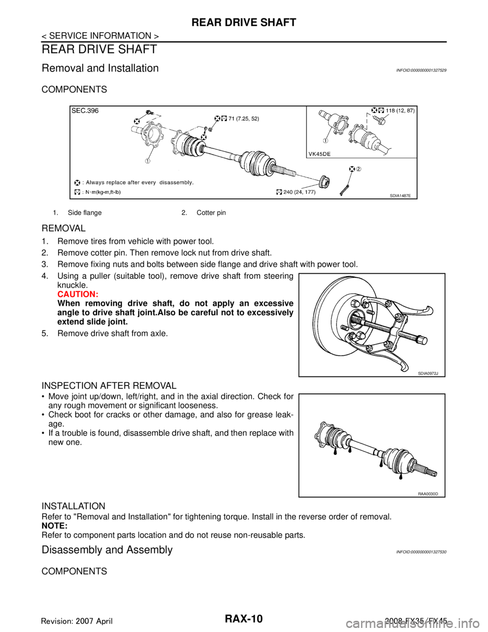
COMPONENTS
REMOVAL
1. Remove tires from vehicle with power tool.
2. Remove cotter pin. Then remove lock nut from drive shaft.
3. Remove fixing nuts and bolts between side flange and drive shaft with power tool.
4. Using a puller (suitable tool), remove drive shaft from steeringknuckle.
CAUTION:
When removing drive shaft, do not apply an excessive
angle to drive shaft joint.Al so be careful not to excessively
extend slide joint.
5. Remove drive shaft from axle.
INSPECTION AFTER REMOVAL
Move joint up/down, left/right, and in the axial direction. Check for any rough movement or significant looseness.
Check boot for cracks or other damage, and also for grease leak- age.
If a trouble is found, disassemble drive shaft, and then replace with
new one.
INSTALLATION
Refer to "Removal and Installation" for tightening torque. Install in the reverse order of removal.
NOTE:
Refer to component parts location and do not reuse non-reusable parts.
Disassembly and AssemblyINFOID:0000000001327530
COMPONENTS
1. Side flange 2. Cotter pin
SDIA1487E
SDIA0972J
RAA0030D
3AA93ABC3ACD3AC03ACA3AC03AC63AC53A913A773A893A873A873A8E3A773A983AC73AC93AC03AC3
3A893A873A873A8F3A773A9D3AAF3A8A3A8C3A863A9D3AAF3A8B3A8C