2008 INFINITI FX35 u1000
[x] Cancel search: u1000Page 1129 of 3924
DTC INDEXDI-3
< SERVICE INFORMATION >
C
DE
F
G H
I
J
L
M A
B
DI
N
O P
SERVICE INFORMATION
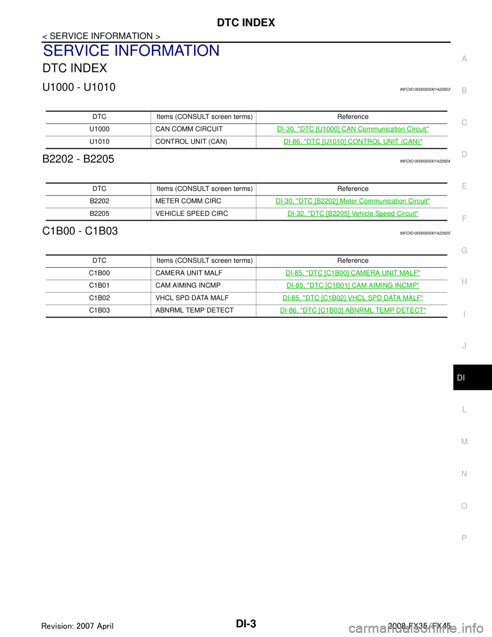
DTC INDEX
U1000 - U1010INFOID:0000000001422603
B2202 - B2205INFOID:0000000001422604
C1B00 - C1B03INFOID:0000000001422605
DTC Items (CONSULT sc reen terms) Reference
U1000 CAN COMM CIRCUIT DI-30, "
DTC [U1000] CAN Communication Circuit"
U1010 CONTROL UNIT (CAN) DI-86, "DTC [U1010] CONTROL UNIT (CAN)"
DTC Items (CONSULT screen terms) Reference
B2202 METER COMM CIRC DI-30, "
DTC [B2202] Meter Communication Circuit"
B2205 VEHICLE SPEED CIRC DI-32, "DTC [B2205] Vehicle Speed Circuit"
DTC Items (CONSULT screen terms) Reference
C1B00 CAMERA UNIT MALF DI-85, "
DTC [C1B00] CAMERA UNIT MALF"
C1B01 CAM AIMING INCMP DI-85, "DTC [C1B01] CAM AIMING INCMP"
C1B02 VHCL SPD DATA MALFDI-85, "DTC [C1B02] VHCL SPD DATA MALF"
C1B03 ABNRML TEMP DETECTDI-86, "DTC [C1B03] ABNRML TEMP DETECT"
3AA93ABC3ACD3AC03ACA3AC03AC63AC53A913A773A893A873A873A8E3A773A983AC73AC93AC03AC3
3A893A873A873A8F3A773A9D3AAF3A8A3A8C3A863A9D3AAF3A8B3A8C
Page 1154 of 3924
DI-28
< SERVICE INFORMATION >
UNIFIED METER AND A/C AMP
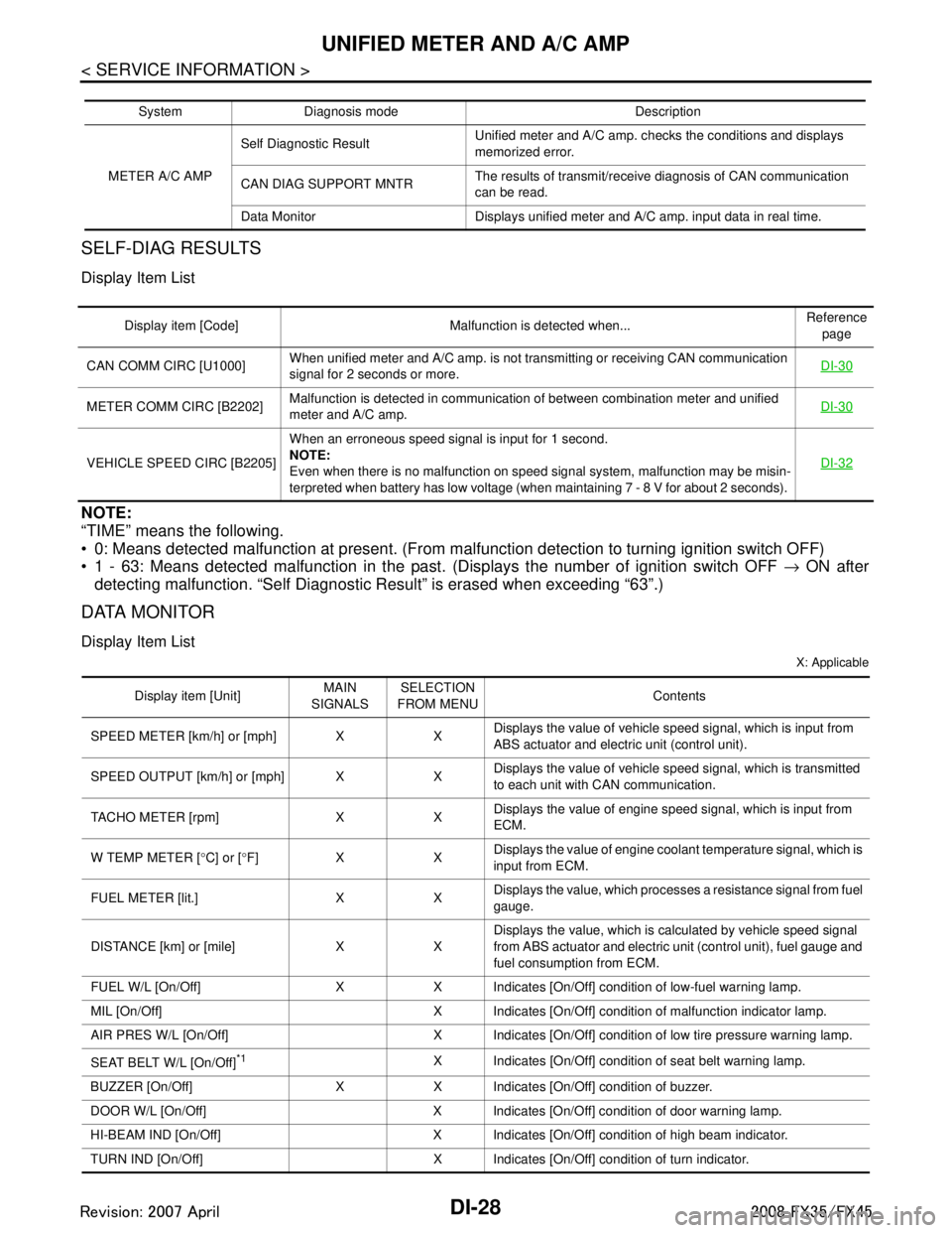
SELF-DIAG RESULTS
Display Item List
NOTE:
“TIME” means the following.
0: Means detected malfunction at present. (From malfunction detection to turning ignition switch OFF)
1 - 63: Means detected malfunction in the past . (Displays the number of ignition switch OFF → ON after
detecting malfunction. “Self Diagnostic Result” is erased when exceeding “63”.)
DATA MONITOR
Display Item List
X: Applicable
System Diagnosis mode Description
METER A/C AMP Self Diagnostic Result
Unified meter and A/C amp. checks the conditions and displays
memorized error.
CAN DIAG SUPPORT MNTR The results of transmit/receive diagnosis of CAN communication
can be read.
Data Monitor Displays unified meter and A/C amp. input data in real time.
Display item [Code] Malfunction is detected when... Reference
page
CAN COMM CIRC [U1000] When unified meter and A/C amp. is not transmitting or receiving CAN communication
signal for 2 seconds or more. DI-30
METER COMM CIRC [B2202]Malfunction is detected in communication of between combination meter and unified
meter and A/C amp.
DI-30
VEHICLE SPEED CIRC [B2205]When an erroneous speed signal is input for 1 second.
NOTE:
Even when there is no malfunction on speed signal system, malfunction may be misin-
terpreted when battery has low voltage (when maintaining 7 - 8 V for about 2 seconds). DI-32
Display item [Unit]
MAIN
SIGNALS SELECTION
FROM MENU Contents
SPEED METER [km/h] or [mph] X X Displays the value of vehicle speed signal, which is input from
ABS actuator and electric unit (control unit).
SPEED OUTPUT [km/h] or [mph] X X Displays the value of vehicle speed signal, which is transmitted
to each unit with CAN communication.
TACHO METER [rpm] X X Displays the value of engine speed signal, which is input from
ECM.
W TEMP METER [ °C] or [ °F] X X Displays the value of engine coolant temperature signal, which is
input from ECM.
FUEL METER [lit.] X X Displays the value, which processes a resistance signal from fuel
gauge.
DISTANCE [km] or [mile] X X Displays the value, which is calculated by vehicle speed signal
from ABS actuator and electric unit
(control unit), fuel gauge and
fuel consumption from ECM.
FUEL W/L [On/Off] X X Indicates [On/Off] condition of low-fuel warning lamp.
MIL [On/Off] X Indicates [On/Off] condition of malfunction indicator lamp.
AIR PRES W/L [On/Off] X Indicates [On/Off] condition of low tire pressure warning lamp.
SEAT BELT W/L [On/Off]
*1X Indicates [On/Off] condition of seat belt warning lamp.
BUZZER [On/Off] X X Indicates [On/Off] condition of buzzer.
DOOR W/L [On/Off] X Indicates [On/Off] condition of door warning lamp.
HI-BEAM IND [On/Off] X Indicates [On/Off] condition of high beam indicator.
TURN IND [On/Off] X Indicates [On/Off] condition of turn indicator.
3AA93ABC3ACD3AC03ACA3AC03AC63AC53A913A773A893A873A873A8E3A773A983AC73AC93AC03AC3
3A893A873A873A8F3A773A9D3AAF3A8A3A8C3A863A9D3AAF3A8B3A8C
Page 1156 of 3924
DI-30
< SERVICE INFORMATION >
UNIFIED METER AND A/C AMP
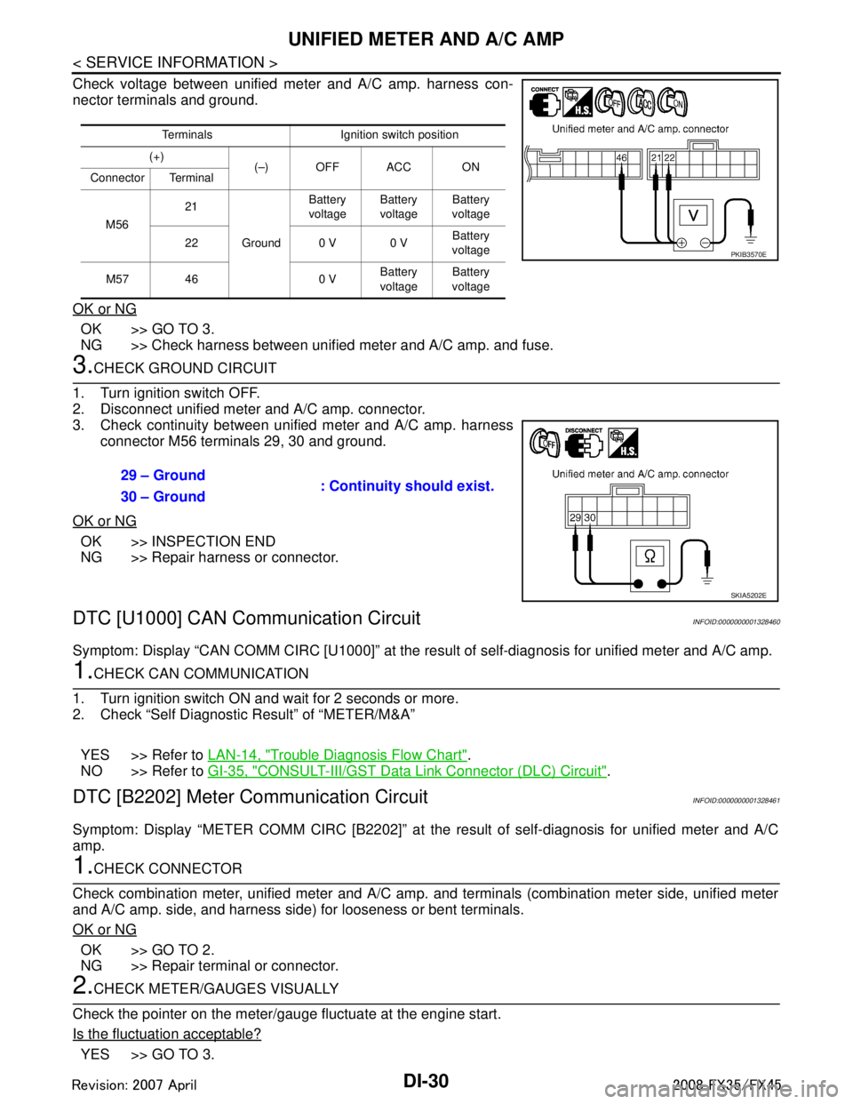
Check voltage between unified meter and A/C amp. harness con-
nector terminals and ground.
OK or NG
OK >> GO TO 3.
NG >> Check harness between unified meter and A/C amp. and fuse.
3.CHECK GROUND CIRCUIT
1. Turn ignition switch OFF.
2. Disconnect unified meter and A/C amp. connector.
3. Check continuity between unified meter and A/C amp. harness connector M56 terminals 29, 30 and ground.
OK or NG
OK >> INSPECTION END
NG >> Repair harness or connector.
DTC [U1000] CAN Communication CircuitINFOID:0000000001328460
Symptom: Display “CAN COMM CIRC [U1000]” at the re sult of self-diagnosis for unified meter and A/C amp.
1.CHECK CAN COMMUNICATION
1. Turn ignition switch ON and wait for 2 seconds or more.
2. Check “Self Diagnostic Result” of “METER/M&A”
YES >> Refer to LAN-14, "
Trouble Diagnosis Flow Chart".
NO >> Refer to GI-35, "
CONSULT-III/GST Data Link Connector (DLC) Circuit".
DTC [B2202] Meter Communication CircuitINFOID:0000000001328461
Symptom: Display “METER COMM CI RC [B2202]” at the result of self-diagnosis for unified meter and A/C
amp.
1.CHECK CONNECTOR
Check combination meter, unified meter and A/C amp. and terminals (combination meter side, unified meter
and A/C amp. side, and harness side) for looseness or bent terminals.
OK or NG
OK >> GO TO 2.
NG >> Repair terminal or connector.
2.CHECK METER/GAUGES VISUALLY
Check the pointer on the meter/gauge fluctuate at the engine start.
Is the fluctuation acceptable?
YES >> GO TO 3.
Terminals Ignition switch position
(+) (–) OFF ACC ON
Connector Terminal
M56 21
Ground Battery
voltage Battery
voltage Battery
voltage
22 0 V 0 V Battery
voltage
M57 46 0 V Battery
voltage Battery
voltage
PKIB3570E
29 – Ground : Continuity should exist.
30 – Ground
SKIA5202E
3AA93ABC3ACD3AC03ACA3AC03AC63AC53A913A773A893A873A873A8E3A773A983AC73AC93AC03AC3
3A893A873A873A8F3A773A9D3AAF3A8A3A8C3A863A9D3AAF3A8B3A8C
Page 1186 of 3924
DI-60
< SERVICE INFORMATION >
WARNING CHIME
CONSULT-III Function (METER/M&A)
INFOID:0000000001328480
Refer to DI-27, "CONSULT-III Function (METER/M&A)" in “UNIFIED METER AND A/C AMP”.
CONSULT-III Function (BCM)INFOID:0000000001328481
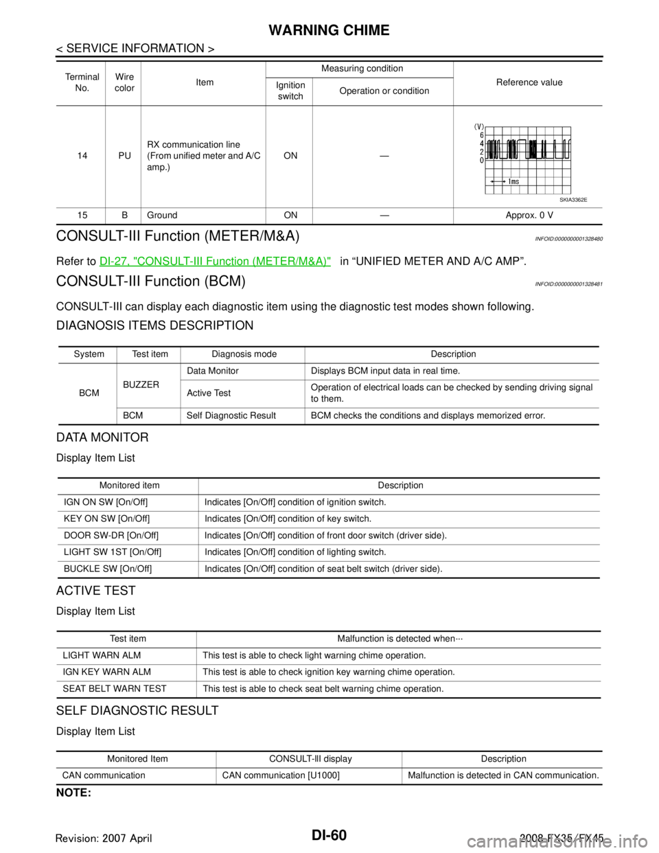
CONSULT-III can display each diagnostic item using the diagnostic test modes shown following.
DIAGNOSIS ITEMS DESCRIPTION
DATA MONITOR
Display Item List
ACTIVE TEST
Display Item List
SELF DIAGNOSTIC RESULT
Display Item List
NOTE:
14 PU RX communication line
(From unified meter and A/C
amp.) ON —
15 B Ground ON — Approx. 0 V
Te r m i n a l
No. Wire
color Item Measuring condition
Reference value
Ignition
switch Operation or condition
SKIA3362E
System Test item Diagnosis mode Description
BCM BUZZER Data Monitor Displays BCM input data in real time.
Active Test
Operation of electrical loads can be checked by sending driving signal
to them.
BCM Self Diagnostic Result BCM checks the conditions and displays memorized error.
Monitored item Description
IGN ON SW [On/Off] Indicates [On/Off] condition of ignition switch.
KEY ON SW [On/Off] Indicates [On/ Off] condition of key switch.
DOOR SW-DR [On/Off] Indicates [On/Off] condition of front door switch (driver side).
LIGHT SW 1ST [On/Off] Indicates [On/Off] condition of lighting switch.
BUCKLE SW [On/Off] Indicates [On/Off] condition of seat belt switch (driver side).
Test item Malfunction is detected when···
LIGHT WARN ALM This test is able to check light warning chime operation.
IGN KEY WARN ALM This test is able to ch eck ignition key warning chime operation.
SEAT BELT WARN TEST This test is able to check seat belt warning chime operation.
Monitored Item CONSULT-llI display Description
CAN communication CAN communication [U1000] Malfunction is detected in CAN communication.
3AA93ABC3ACD3AC03ACA3AC03AC63AC53A913A773A893A873A873A8E3A773A983AC73AC93AC03AC3
3A893A873A873A8F3A773A9D3AAF3A8A3A8C3A863A9D3AAF3A8B3A8C
Page 1187 of 3924
![INFINITI FX35 2008 Service Manual
WARNING CHIMEDI-61
< SERVICE INFORMATION >
C
DE
F
G H
I
J
L
M A
B
DI
N
O P
If “CAN communication [U1000]” is indicated, after prin ting the monitor item, go to “LAN system”. Refer to
LAN-43, INFINITI FX35 2008 Service Manual
WARNING CHIMEDI-61
< SERVICE INFORMATION >
C
DE
F
G H
I
J
L
M A
B
DI
N
O P
If “CAN communication [U1000]” is indicated, after prin ting the monitor item, go to “LAN system”. Refer to
LAN-43,](/manual-img/42/57017/w960_57017-1186.png)
WARNING CHIMEDI-61
< SERVICE INFORMATION >
C
DE
F
G H
I
J
L
M A
B
DI
N
O P
If “CAN communication [U1000]” is indicated, after prin ting the monitor item, go to “LAN system”. Refer to
LAN-43, "
CAN System Specification Chart".
Trouble DiagnosisINFOID:0000000001328482
HOW TO PERFORM TROUBLE DIAGNOSIS
1. Confirm the symptom or customer complaint.
2. Understand operation description and function description. Refer to DI-51, "
System Description".
3. Perform the preliminary inspection. Refer to "PRELIMINARY INSPECTION".
4. Referring to trouble diagnosis chart, make sure the cause of the malfunction and repair or replace applica-
ble parts. Refer to DI-61, "
Symptom Chart".
5. Does the warning chime operate normally? If so, GO TO 6. If not, GO TO 3.
6. INSPECTION END
PRELIMINARY INSPECTION
1.CHECK BCM (CONSULT-III)
Perform self-diagnosis of BCM. Refer to DI-60, "
CONSULT-III Function (BCM)".
Self
-diagnosis results
No malfunction detected >> GO TO 2.
Malfunction detected >> Check applicable parts, and repair or replace corresponding parts.
2.CHECK UNIFIED METER AND A/C AMP. (CONSULT-III)
Perform self-diagnosis of unified meter and A/C amp. Refer to DI-27, "
CONSULT-III Function (METER/M&A)".
Self
-diagnosis results
No malfunction detected >> INSPECTION END
Malfunction detected >> Check applicable parts, and repair or replace corresponding parts.
Symptom ChartINFOID:0000000001328483
Power Supply and Ground Circuit InspectionINFOID:0000000001328484
1.CHECK FUSE AND FUSIBLE LINK
Check for blown BCM fuses and fusible link.
Symptom Diagnoses/Service procedure
All warning chimes do not activate. Perform the following inspections.
1.
DI-62, "
Combination Meter Buzzer Circuit Inspection".
2. DI-61, "
Power Supply and Ground Circuit Inspection".
Replace BCM, found normal function in the above inspections.
Ignition key
warning chime
does not acti-
vate. Without Intelligent Key.
Perform the following inspections.
1.
DI-63, "
Front Door Switch (Drive r Side) Signal Inspection".
2. DI-64, "
Key Switch Signal Inspection (Without Intelligent Key)".
Replace BCM, found normal function in the above inspections.
With Intelligent Key, when mechan-
ical key is used. Perform the following inspections.
1.
DI-63, "
Front Door Switch (Drive r Side) Signal Inspection".
2. DI-65, "
Key Switch and Ignition Knob Switch Signal Inspection (With In-
telligent Key, When Mechanical Key Is Used)".
Replace BCM, found normal function in the above inspections.
With Intelligent Key, when Intelli-
gent Key is carried with the driver. Refer to
BL-106, "
Trouble Diagnosis Symptom Chart".
Light warning chime does not activate. Perform the following inspections.
1.
DI-63, "
Front Door Switch (Drive r Side) Signal Inspection".
2. LT- 1 0 4 , "
Combination Switch Inspection".
Replace BCM, found normal function in the above inspections.
Seat belt warning chime does not activate. Perform
DI-66, "
Seat Belt Buckle Switch (D river Side) Signal Inspection".
Replace BCM, found normal function in the above inspection.
3AA93ABC3ACD3AC03ACA3AC03AC63AC53A913A773A893A873A873A8E3A773A983AC73AC93AC03AC3
3A893A873A873A8F3A773A9D3AAF3A8A3A8C3A863A9D3AAF3A8B3A8C
Page 1208 of 3924
![INFINITI FX35 2008 Service Manual
DI-82
< SERVICE INFORMATION >
LANE DEPARTURE WARNING SYSTEM
NOTE:
When a DTC is detected, the LDW system dose not operate.
When the DTC except “ABNRML TEMP DETECT [C1B03] ” is detected, the INFINITI FX35 2008 Service Manual
DI-82
< SERVICE INFORMATION >
LANE DEPARTURE WARNING SYSTEM
NOTE:
When a DTC is detected, the LDW system dose not operate.
When the DTC except “ABNRML TEMP DETECT [C1B03] ” is detected, the](/manual-img/42/57017/w960_57017-1207.png)
DI-82
< SERVICE INFORMATION >
LANE DEPARTURE WARNING SYSTEM
NOTE:
When a DTC is detected, the LDW system dose not operate.
When the DTC except “ABNRML TEMP DETECT [C1B03] ” is detected, the LDW indicator lamp turns ON.
When the DTC “ABNRML TEMP DETECT [C1B03] ” is detected, the LDW system ON indicator lamp blinks.
DATA MONITOR
Display Item
ACTIVE TEST
CAUTION:
Never perform the active test while driving.
Active test cannot be started while LDW indicator lamp is illuminated.
Display item [Code] Malfunctions detected where... Reference
page
CAMERA UNIT MALF [C1B00] LDW camera unit internal malfunction DI-85
CAM AIMING INCMP [C1B01] LDW camera aiming is not adjusted. DI-85
VHCL SPD DATA MALF [C1B02]LDW camera unit detected different vehicle speed signal from TCM and ABS ac-
tuator and electric unit (control unit). DI-85
ABNRML TEMP DETECT [C1B03] Temperature around LDW camera unit is excessively high.
DI-86
CAN COMM CIRCUIT [U1000] LDW camera unit detected CAN communication malfunction. DI-86
CONTROL UNIT (CAN) [U1010] LDW camera unit detected internal CAN communication circuit malfunction. DI-86
Monitored Item [unit] Description
VHCL SPD SE [km/h] or [mph] Displays vehicle speed calculated by LDW camera unit through CAN communication [ABS
actuator and electric unit (control unit) transmits wheel sensor signal through CAN communi-
cation].
VHCL SPD AT [km/h] or [mph] Displays vehicle speed calculated from A/T vehicle speed sensor by LDW camera unit
through CAN communication (TCM transmits A/T vehicle speed sensor signal through CAN
communication).
FCTRY AIM YAW [deg] Displays camera unit installation condition.
FCTRY AIM ROL [deg] Displays camera unit installation condition.
FCTRY AIM PIT [deg] Displays camera unit installation condition.
XOFFSET [pixel] Displays camera unit installation condition.
MAIN SW [On/Off] Displays [On/Off] status as judged from LDW switch signal.
SW ON LAMP [On/Off] Displays [On/Off] status of LDW system ON indicator signal output.
INDICATE LAMP [On/Off] Displays [On/Off] status of LDW indicator signal output.
BUZZER OUTPUT [On/Off] Displays [On/Off] status of LDW chime operation signal output.
LDW INACCURAT [On/Off] Displays LDW camera unit status.
TURN SIGNAL [Off/LH/RH] Displays “Tur n signal” status, determined from BCM thro ugh CAN communication.
LANE DETCT LH [On/Off] Displays left lane marker is detected.
LANE DETCT RH [On/Off] Displays right lane marker is detected.
CROSS LANE LH [On/Off] Displays vehicle is crossing left lane.
CROSS LANE RH [On/Off] Displays vehicle is crossing right lane.
WARN LANE LH [On/Off] Displays warning for left lane.
WARN LANE RH [On/Off] Displays warning for right lane.
VALID POS LH [VLD/INVLD] Displays lateral position for left lane marker is valid.
VALID POS RH [VLD/INVLD] Displays lateral position for right lane marker is valid.
AIMING DONE [OK/NG] Displa ys camera aiming done.
AIMING RESULT [OK/NOK] Disp lays camera aiming result.
3AA93ABC3ACD3AC03ACA3AC03AC63AC53A913A773A893A873A873A8E3A773A983AC73AC93AC03AC3
3A893A873A873A8F3A773A9D3AAF3A8A3A8C3A863A9D3AAF3A8B3A8C
Page 1212 of 3924
DI-86
< SERVICE INFORMATION >
LANE DEPARTURE WARNING SYSTEM
Perform self-diagnosis of ABS actuator and electric unit (control unit). Refer to \
BRC-26, "CONSULT-III Func-
tions (ABS)".
Self
-diagnosis results
No malfunction detected >> GO TO 2.
Malfunction detected >> Check applicable parts, and repair or replace corresponding parts.
2.CHECK TCM (CONSULT-III)
Perform self-diagnosis of TCM. Refer to AT-84, "
CONSULT-III Function (TRANSMISSION)".
Self
-diagnosis results
No malfunction detected >> Replace LDW camera unit.
Malfunction detected >> Check applicable parts, and repair or replace corresponding parts.
DTC [C1B03] ABNRML TEMP DETECTINFOID:0000000001328507
1.COOLING CAMERA UNIT
1. Cooling camera unit.
2. Erase DTC and perform self-diagnosis the LDW camera unit.
Self
-diagnosis results
No malfunction detected >> INSPECTION END
Malfunction detected >> Replace LDW camera unit.
DTC [U1000] CAN COMM CIRCUITINFOID:0000000001328508
1.CHECK CAN COMMUNICATION
1. Turn ignition switch ON and wait for 2 seconds or more.
2. Check “Self Diagnostic Result” of “LDW”.
>> Go to “LAN SYSTEM”. Refer to LAN-43, "
CAN System Specification Chart".
DTC [U1010] CONTROL UNIT (CAN)INFOID:0000000001328509
Replace LDW camera unit, when “[U1010] CONTROL UNI T (CAN)” is displayed on self-diagnosis display.
LDW Chime Circuit InspectionINFOID:0000000001328510
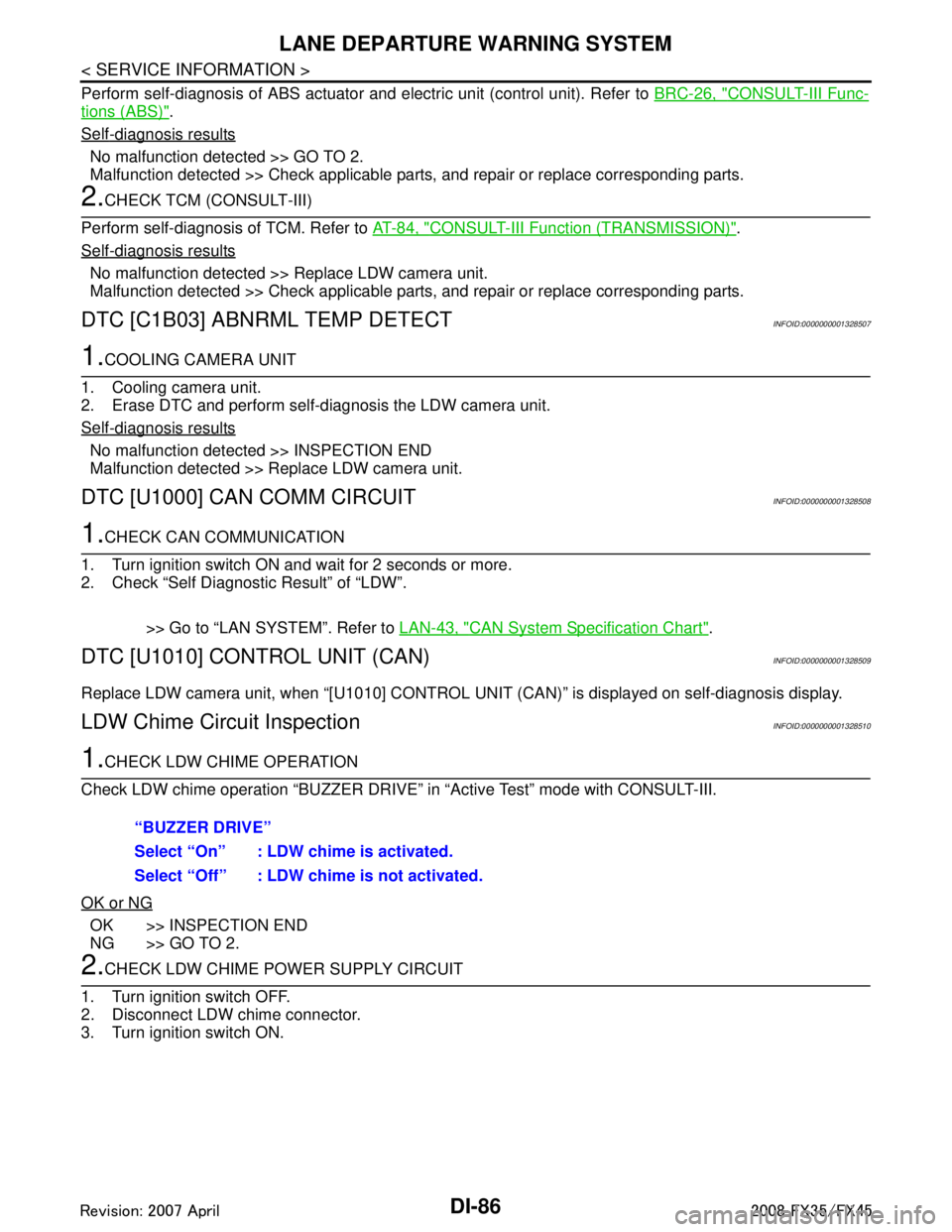
1.CHECK LDW CHIME OPERATION
Check LDW chime operation “BUZZER DRIVE” in “Active Test” mode with CONSULT-III.
OK or NG
OK >> INSPECTION END
NG >> GO TO 2.
2.CHECK LDW CHIME POWER SUPPLY CIRCUIT
1. Turn ignition switch OFF.
2. Disconnect LDW chime connector.
3. Turn ignition switch ON. “BUZZER DRIVE”
Select “On” : LDW chime is activated.
Select “Off” : LDW chime is not activated.
3AA93ABC3ACD3AC03ACA3AC03AC63AC53A913A773A893A873A873A8E3A773A983AC73AC93AC03AC3
3A893A873A873A8F3A773A9D3AAF3A8A3A8C3A863A9D3AAF3A8B3A8C
Page 1242 of 3924

EC-2
Circuit Diagram ......................................................107
ECM Harness Connector Terminal Layout ............109
ECM Terminal and Reference Value .....................109
CONSULT-III Function (ENGINE) .........................117
Generic Scan Tool (GST) Function .......................125
CONSULT-III Reference Value in Data Monitor
Mode .................................................................... ..
127
TROUBLE DIAGNOSIS - SPECIFICATION
VALUE .............................................................
131
Description ........................................................... ..131
Testing Condition ...................................................131
Inspection Procedure .............................................131
Diagnosis Procedure .............................................131
TROUBLE DIAGNOSIS FOR INTERMITTENT
INCIDENT ........................................................
139
Description ........................................................... ..139
Diagnosis Procedure .............................................139
POWER SUPPLY AND GROUND CIRCUIT ...140
Wiring Diagram .................................................... ..140
Diagnosis Procedure .............................................141
Ground Inspection .................................................144
DTC U1000, U1001 CAN COMMUNICATION
LINE .................................................................
146
Description ........................................................... ..146
On Board Diagnosis Logic .....................................146
DTC Confirmation Procedure ................................146
Wiring Diagram ......................................................147
Diagnosis Procedure .............................................147
DTC U1010 CAN COMMUNICATION .............148
Description ........................................................... ..148
On Board Diagnosis Logic .....................................148
DTC Confirmation Procedure ................................148
Diagnosis Procedure .............................................148
DTC P0011, P0021 IVT CONTROL .................149
Description ........................................................... ..149
CONSULT-III Reference Value in Data Monitor
Mode .................................................................... ..
149
On Board Diagnosis Logic .....................................150
DTC Confirmation Procedure ................................150
Diagnosis Procedure .............................................151
Component Inspection ...........................................152
Removal and Installation .......................................152
DTC P0031, P0032, P0051, P0052 A/F SEN-
SOR 1 HEATER ...............................................
153
Description ........................................................... ..153
CONSULT-III Reference Value in Data Monitor
Mode .................................................................... ..
153
On Board Diagnosis Logic .....................................153
DTC Confirmation Procedure ................................153
Wiring Diagram ......................................................154
Diagnosis Procedure .............................................157
Component Inspection ...........................................158
Removal and Installation .......................................159
DTC P0037, P0038, P0057, P0058 HO2S2
HEATER ...........................................................
160
Description ........................................................... .160
CONSULT-III Reference Value in Data Monitor
Mode .....................................................................
160
On Board Diagnosis Logic ....................................160
DTC Confirmation Procedure ................................160
Wiring Diagram .....................................................162
Diagnosis Procedure .............................................165
Component Inspection ..........................................166
Removal and Installation .......................................167
DTC P0075, P0081 IVT CONTROL SOLE-
NOID VALVE ....................................................
168
Component Description ....................................... .168
CONSULT-III Reference Value in Data Monitor
Mode .....................................................................
168
On Board Diagnosis Logic ....................................168
DTC Confirmation Procedure ................................168
Wiring Diagram .....................................................169
Diagnosis Procedure .............................................172
Component Inspection ..........................................173
Removal and Installation .......................................174
DTC P0101 MAF SENSOR ..............................175
Component Description ....................................... .175
CONSULT-III Reference Value in Data Monitor
Mode .....................................................................
175
On Board Diagnosis Logic ....................................175
DTC Confirmation Procedure ................................175
Overall Function Check .........................................176
Wiring Diagram .....................................................177
Diagnosis Procedure .............................................178
Component Inspection ..........................................180
Removal and Installation .......................................181
DTC P0102, P0103 MAF SENSOR ..................182
Component Description ....................................... .182
CONSULT-III Reference Value in Data Monitor
Mode .....................................................................
182
On Board Diagnosis Logic ....................................182
DTC Confirmation Procedure ................................182
Wiring Diagram .....................................................184
Diagnosis Procedure .............................................185
Component Inspection ..........................................187
Removal and Installation .......................................188
DTC P0112, P0113 IAT SENSOR ....................189
Component Description ....................................... .189
On Board Diagnosis Logic ....................................189
DTC Confirmation Procedure ................................189
Wiring Diagram .....................................................190
Diagnosis Procedure .............................................190
Component Inspection ..........................................192
Removal and Installation .......................................192
DTC P0117, P0118 ECT SENSOR ...................193
Component Description ....................................... .193
On Board Diagnosis Logic ....................................193
DTC Confirmation Procedure ................................194
3AA93ABC3ACD3AC03ACA3AC03AC63AC53A913A773A893A873A873A8E3A773A983AC73AC93AC03AC3
3A893A873A873A8F3A773A9D3AAF3A8A3A8C3A863A9D3AAF3A8B3A8C