2008 INFINITI FX35 mirror
[x] Cancel search: mirrorPage 2998 of 3924
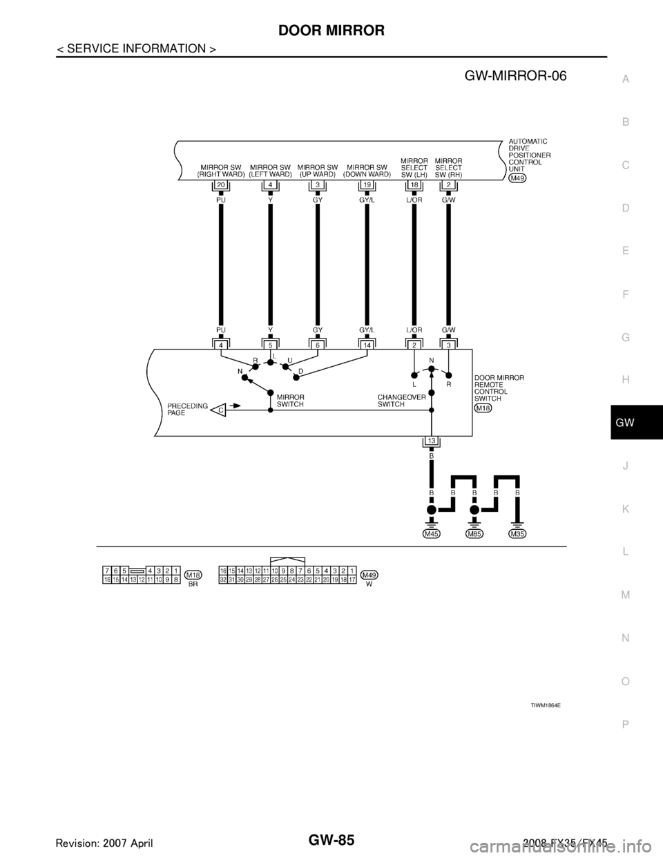
DOOR MIRRORGW-85
< SERVICE INFORMATION >
C
DE
F
G H
J
K L
M A
B
GW
N
O P
TIWM1864E
3AA93ABC3ACD3AC03ACA3AC03AC63AC53A913A773A893A873A873A8E3A773A983AC73AC93AC03AC3
3A893A873A873A8F3A773A9D3AAF3A8A3A8C3A863A9D3AAF3A8B3A8C
Page 2999 of 3924
GW-86
< SERVICE INFORMATION >
DOOR MIRROR
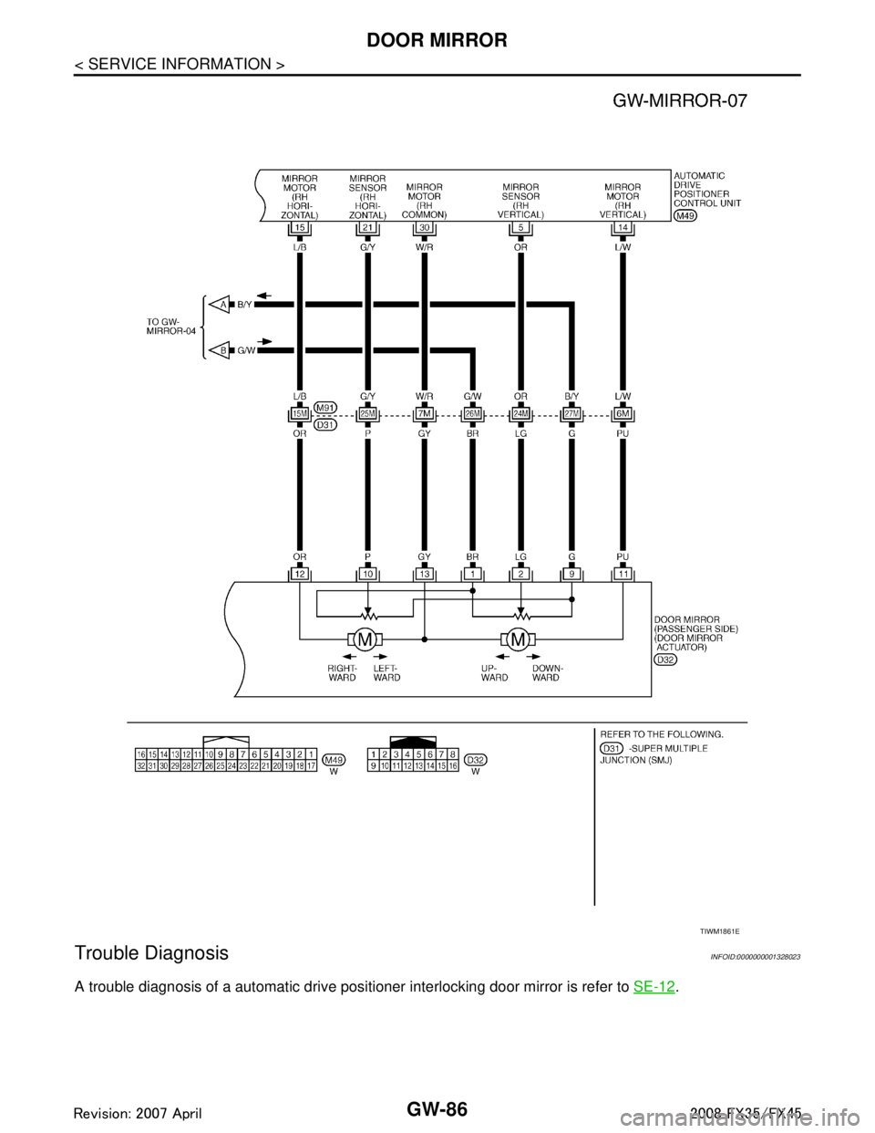
Trouble Diagnosis
INFOID:0000000001328023
A trouble diagnosis of a automatic drive positi oner interlocking door mirror is refer to SE-12.
TIWM1861E
3AA93ABC3ACD3AC03ACA3AC03AC63AC53A913A773A893A873A873A8E3A773A983AC73AC93AC03AC3
3A893A873A873A8F3A773A9D3AAF3A8A3A8C3A863A9D3AAF3A8B3A8C
Page 3000 of 3924
DOOR MIRRORGW-87
< SERVICE INFORMATION >
C
DE
F
G H
J
K L
M A
B
GW
N
O P
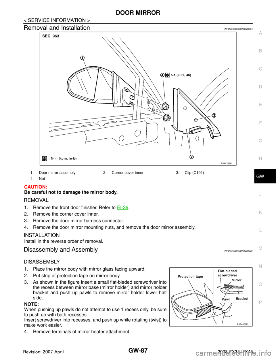
Removal and InstallationINFOID:0000000001328024
CAUTION:
Be careful not to damage the mirror body.
REMOVAL
1. Remove the front door finisher. Refer to EI-36.
2. Remove the corner cover inner.
3. Remove the door mirror harness connector.
4. Remove the door mirror mounting nuts, and remove the door mirror assembly.
INSTALLATION
Install in the reverse order of removal.
Disassembly and AssemblyINFOID:0000000001328025
DISASSEMBLY
1. Place the mirror body with mirror glass facing upward.
2. Put strip of protection tape on mirror body.
3. As shown in the figure insert a small flat-bladed screwdriver into the recess between mirror base (mirror holder) and mirror holder
bracket and push up pawls to remove mirror holder lower half
side.
NOTE:
When pushing up pawls do not attempt to use 1 recess only, be sure
to push up with both recesses.
Insert screwdriver into recesses, and push up while rotating (twist) to
make work easier.
4. Remove terminals of mirror heater attachment.
PIIA4738E
1. Door mirror assembly 2. Corn er cover inner 3. Clip (C101)
4. Nut
PIIA4002E
3AA93ABC3ACD3AC03ACA3AC03AC63AC53A913A773A893A873A873A8E3A773A983AC73AC93AC03AC3
3A893A873A873A8F3A773A9D3AAF3A8A3A8C3A863A9D3AAF3A8B3A8C
Page 3001 of 3924
GW-88
< SERVICE INFORMATION >
DOOR MIRROR
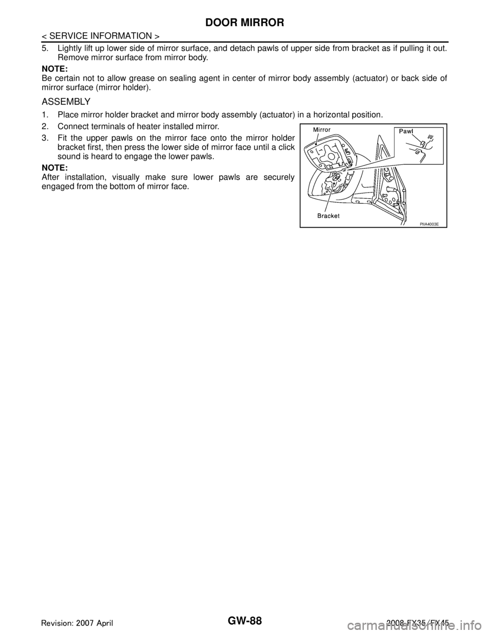
5. Lightly lift up lower side of mirror surface, and detach pawls of upper side from bracket as if pulling it out.
Remove mirror surface from mirror body.
NOTE:
Be certain not to allow grease on sealing agent in cent er of mirror body assembly (actuator) or back side of
mirror surface (mirror holder).
ASSEMBLY
1. Place mirror holder bracket and mirror body assembly (actuator) in a horizontal position.
2. Connect terminals of heater installed mirror.
3. Fit the upper pawls on the mirror face onto the mirror holder bracket first, then press the lower side of mirror face until a click
sound is heard to engage the lower pawls.
NOTE:
After installation, visually make sure lower pawls are securely
engaged from the bottom of mirror face.
PIIA4003E
3AA93ABC3ACD3AC03ACA3AC03AC63AC53A913A773A893A873A873A8E3A773A983AC73AC93AC03AC3
3A893A873A873A8F3A773A9D3AAF3A8A3A8C3A863A9D3AAF3A8B3A8C
Page 3017 of 3924
IP-16
< SERVICE INFORMATION >
INSTRUMENT PANEL ASSEMBLY
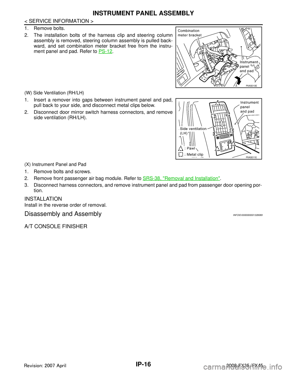
1. Remove bolts.
2. The installation bolts of the harness clip and steering columnassembly is removed, steering column assembly is pulled back-
ward, and set combination meter bracket free from the instru-
ment panel and pad. Refer to PS-12
.
(W) Side Ventilation (RH/LH)
1. Insert a remover into gaps between instrument panel and pad,
pull back to your side, and disconnect metal clips below.
2. Disconnect door mirror switch harness connectors, and remove side ventilation (RH/LH).
(X) Instrument Panel and Pad
1. Remove bolts and screws.
2. Remove front passenger air bag module. Refer to SRS-38, "
Removal and Installation".
3. Disconnect harness connectors, and remove instrum ent panel and pad from passenger door opening por-
tion.
INSTALLATION
Install in the reverse order of removal.
Disassembly and AssemblyINFOID:0000000001328089
A/T CONSOLE FINISHER
PIIA5010E
PIIA5011E
3AA93ABC3ACD3AC03ACA3AC03AC63AC53A913A773A893A873A873A8E3A773A983AC73AC93AC03AC3
3A893A873A873A8F3A773A9D3AAF3A8A3A8C3A863A9D3AAF3A8B3A8C
Page 3243 of 3924

INTERIOR ROOM LAMPLT-141
< SERVICE INFORMATION >
C
DE
F
G H
I
J
L
M A
B
LT
N
O P
When personal lamp RH or LH switch is ON, ground supplied
to personal lamp RH or LH terminal 3
through grounds M35, M45 and M85.
And power is supplied
from BCM terminal 41
to personal lamp LH or RH terminal 2.
When vanity mirror lamp (driver side or passenger side) is ON, ground is supplied
to vanity mirror lamp (driver side or passenger side) terminal 2
through grounds M35, M45 and M85.
And power is supplied
from BCM terminal 41
to vanity mirror lamp (driver side or passenger side) terminal 1.
When luggage room lamp (back door side) is ON, ground is supplied
to luggage room lamp (back door side) terminal 3
through grounds B15 and B45.
And power is supplied
from BCM terminal 41
to luggage room lamp (back door side) terminals 2.
ROOM LAMP TIMER OPERATION
Without Intelligent Key System
When the interior room lamp and map lamp switch is in DOOR position, and when all conditions below are
met, BCM performs timer control (maximum 30 seconds ) for interior room lamp and map lamp ON/OFF.
In addition, when spot turns ON or OFF there is gradual brightening or dimming over 1 second.
Power is supplied
to 15A fuse [No. 22, located infuse block (J/B)]
through key switch terminal 2.
Key is removed from ignition key cylinder (key switch OFF), power will not be supplied to BCM terminal 37.
Ground is supplied
from BCM terminal 22
to power window main switch (door lock and unlock switch) terminal 14.
At the time that driver door are opened, BCM detects that driver door is unlocked. It determines that interior
room lamp and map lamp timer operation conditions are met, and turns interior room lamp and map lamp ON
for 30 seconds.
Key is in ignition key cylinder (key switch ON),
Power is supplied
through key switch terminal 1
to BCM terminal 37.
When the key is removed from key switch (key switch OFF), power supply to BCM terminal 37 is terminated.
BCM detects that key has been removed, determines that interior room lamp and map lamp timer conditions
are met, and turns interior room lamp and map lamp ON for 30 seconds.
When driver door opens → closes, and key is not inserted in key s witch (key switch OFF), BCM terminal 62
changes between 0V (door open) → 12V (door closed). BCM determines that conditions for interior room lamp
and map lamp operation are met and turns interior room lamp ON for 30 seconds.
Timer control is canceled under the following conditions.
Driver door is locked [when locked keyfob or power wi ndow main switch (door lock and unlock switch), door
key cylinder switch].
Driver door is opened (driver door switch turns ON).
Ignition switch ON.
With Intelligent Key System
When the interior room lamp and map lamp switch is in DOOR position, and when all conditions below are
met, BCM performs timer control (maximum 30 second) for interior room lamp and map lamp ON/OFF.
In addition, when spot turns ON or OFF there is gradual brightening or dimming over 1 second.
Power is supplied
to 15A fuse [No. 22, located in fuse and fuse block (J/B)]
through key switch and ignition knob switch terminal 3.
Key is removed from ignition key cylinder (key switch OFF), power will not be supplied to BCM terminal 37.
And not turned ignition knob switch, power will not be supplied to Intelligent Key unit.
Ground is supplied
from BCM terminal 22
3AA93ABC3ACD3AC03ACA3AC03AC63AC53A913A773A893A873A873A8E3A773A983AC73AC93AC03AC3
3A893A873A873A8F3A773A9D3AAF3A8A3A8C3A863A9D3AAF3A8B3A8C
Page 3244 of 3924

LT-142
< SERVICE INFORMATION >
INTERIOR ROOM LAMP
to power window main switch (door lock and unlock switch) terminal 14.
At the time that driver door are opened, BCM detects that driver door is unlocked. It determines that interior
room lamp and map lamp timer operation conditions are met, and turns interior room lamp and map lamp ON
for 30 seconds.
Key is in ignition key cylinder (key swit ch ON), or turned ignition knob switch,
Power is supplied
through key switch and ignition knob switch terminal 4
to BCM terminal 37,
through key switch and ignition knob switch terminal 2
to intelligent key unit terminal 27.
When the key is removed from key switch (key switch OFF), power supply to BCM terminal 37 is terminated.
And turned ignition knob switch, power supply to Intel ligent Key unit is terminated. BCM detects that key has
been removed, determines that interior room lamp and map lamp timer conditions are met, and turns interior
room lamp and map lamp ON for 30 seconds.
When driver door opens → closes, and key is not inserted in key s witch (or not turned ignition knob switch),
BCM terminal 62 changes between 0V (door open) → 12V (door closed). BCM determines that conditions for
interior room lamp and map lamp operation are met and turns interior room lamp ON for 30 seconds.
Timer control is canceled under the following conditions.
Driver door is locked [when locked keyfob, power window main switch (door lock and unlock switch) or door
key cylinder switch].
Driver door is opened (driver door switch terns ON).
Ignition switch ON.
INTERIOR LAMP BATTERY SAVER CONTROL
If lamps is left “ON”, it will not be turned out even when door is closed.
BCM turns off lamps automatically to save battery 30 minutes after ignition switch is turned off.
BCM controls lamps listed below:
Ignition key hole illumination
Front step lamp (driver side)
Front step lamp (passenger side)
Rear step lamp RH
Rear step lamp LH
Front door inside handle illumination (driver side)
Front door inside handle illumination (passenger side)
Rear door inside handle illumination RH
Rear door inside handle illumination LH
Personal lamp RH
Personal lamp LH
Interior room lamp (without DVD player)
Map lamp
Vanity mirror lamp
Luggage room lamp
After lamps turn OFF by battery sa ver system, lamps illuminate again when
signal from keyfob, or power window main switch (door lock and unlock switch) or key cylinder is locked or
unlocked,
door is opened or closed,
key is removed from ignition key cylinder or inserted in ignition key cylinder, or turned ignition knob switch.
Interior lamp battery saver control period can be changed by the function setting of CONSULT-III.
3AA93ABC3ACD3AC03ACA3AC03AC63AC53A913A773A893A873A873A8E3A773A983AC73AC93AC03AC3
3A893A873A873A8F3A773A9D3AAF3A8A3A8C3A863A9D3AAF3A8B3A8C
Page 3267 of 3924
INTERIOR ROOM LAMPLT-165
< SERVICE INFORMATION >
C
DE
F
G H
I
J
L
M A
B
LT
N
O P
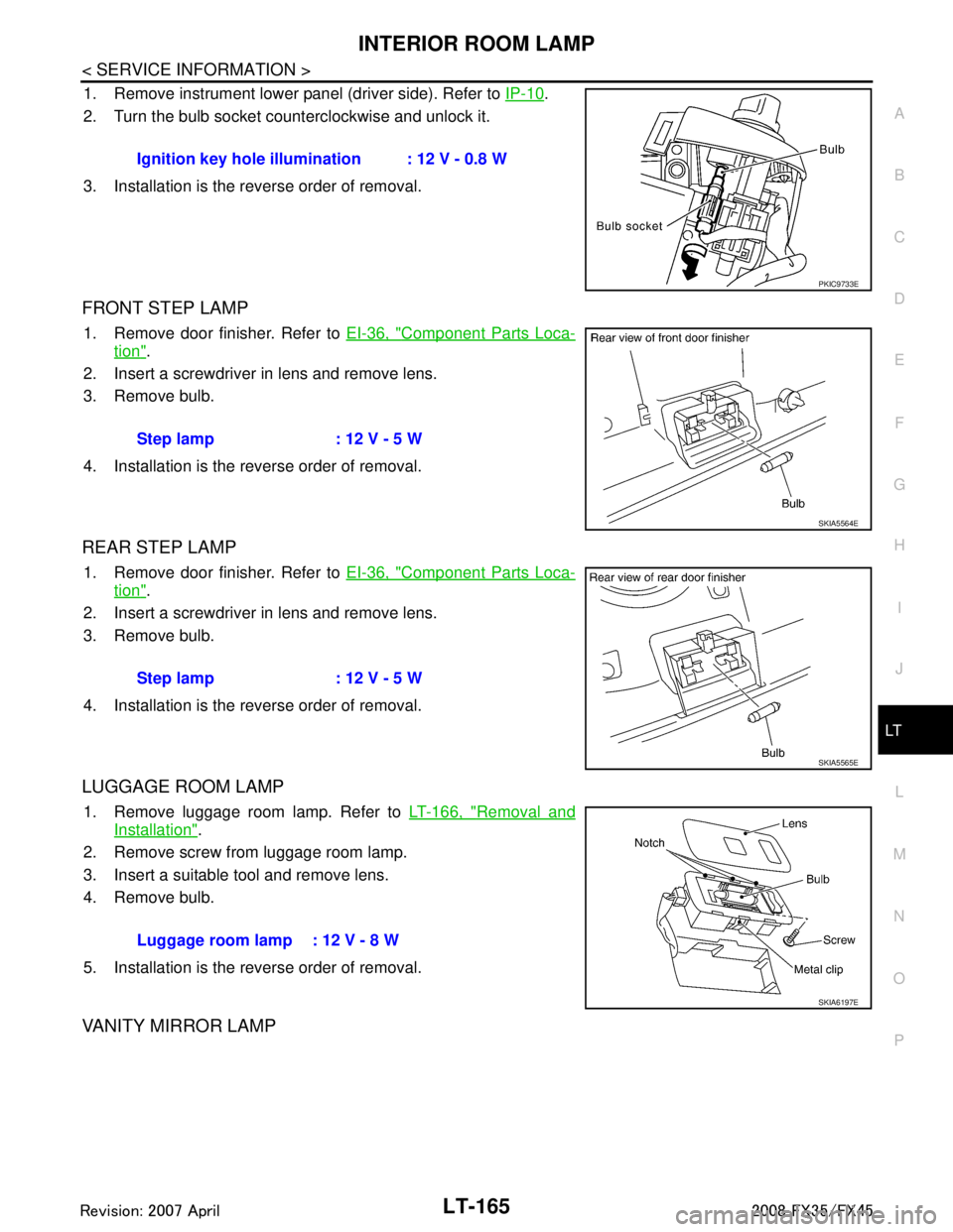
1. Remove instrument lower panel (driver side). Refer to IP-10.
2. Turn the bulb socket counterclockwise and unlock it.
3. Installation is the reverse order of removal.
FRONT STEP LAMP
1. Remove door finisher. Refer to EI-36, "Component Parts Loca-
tion".
2. Insert a screwdriver in lens and remove lens.
3. Remove bulb.
4. Installation is the reverse order of removal.
REAR STEP LAMP
1. Remove door finisher. Refer to EI-36, "Component Parts Loca-
tion".
2. Insert a screwdriver in lens and remove lens.
3. Remove bulb.
4. Installation is the reverse order of removal.
LUGGAGE ROOM LAMP
1. Remove luggage room lamp. Refer to LT-166, "Removal and
Installation".
2. Remove screw from luggage room lamp.
3. Insert a suitable tool and remove lens.
4. Remove bulb.
5. Installation is the reverse order of removal.
VANITY MIRROR LAMP
Ignition key hole illumination : 12 V - 0.8 W
PKIC9733E
Step lamp : 12 V - 5 W
SKIA5564E
Step lamp : 12 V - 5 W
SKIA5565E
Luggage room lamp : 12 V - 8 W
SKIA6197E
3AA93ABC3ACD3AC03ACA3AC03AC63AC53A913A773A893A873A873A8E3A773A983AC73AC93AC03AC3
3A893A873A873A8F3A773A9D3AAF3A8A3A8C3A863A9D3AAF3A8B3A8C