2008 INFINITI FX35 warning
[x] Cancel search: warningPage 3778 of 3924
SIDE CURTAIN AIR BAG MODULESRS-41
< SERVICE INFORMATION >
C
DE
F
G
I
J
K L
M A
B
SRS
N
O P
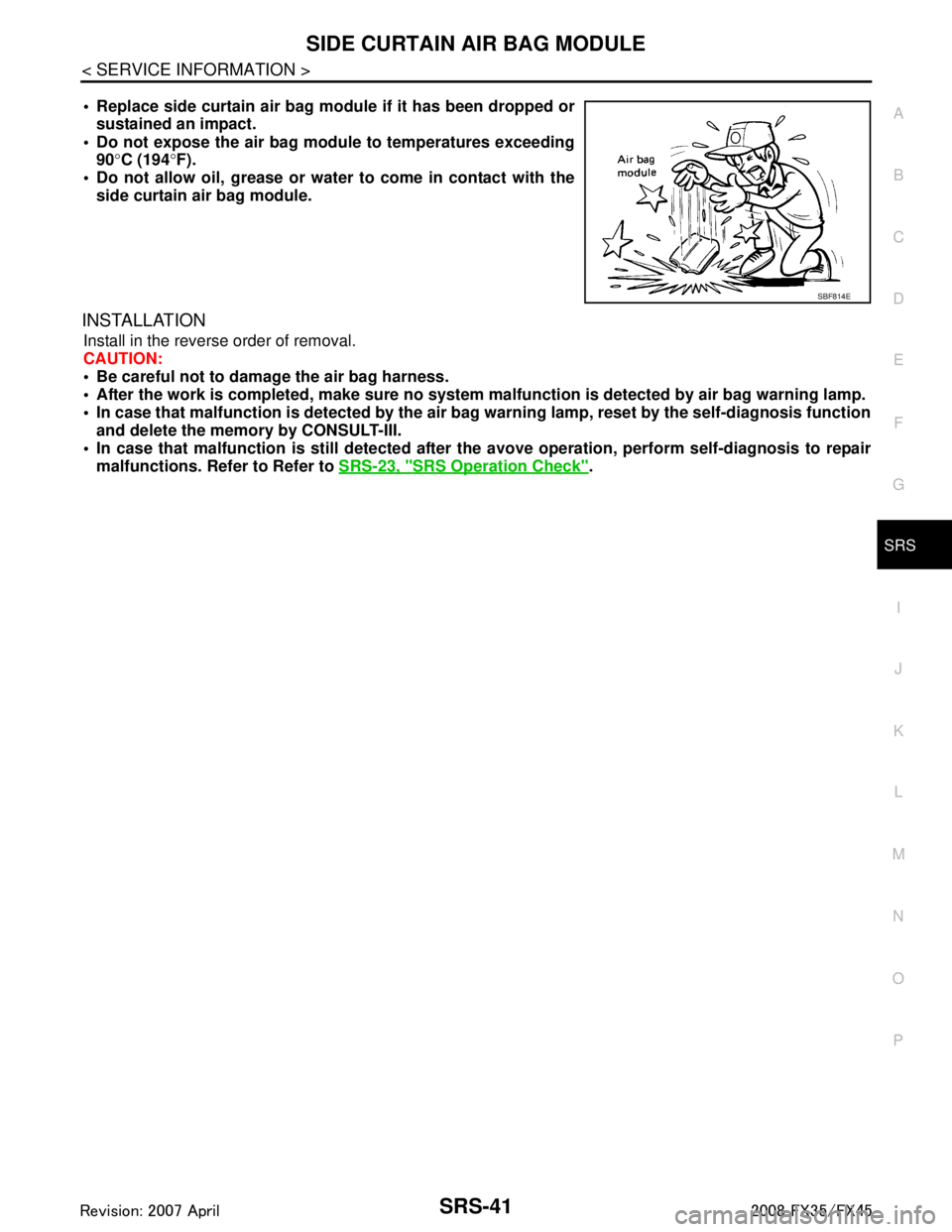
Replace side curtain air bag modu le if it has been dropped or
sustained an impact.
Do not expose the air bag mo dule to temperatures exceeding
90 °C (194 °F).
Do not allow oil, grease or water to come in contact with the
side curtain air bag module.
INSTALLATION
Install in the reverse order of removal.
CAUTION:
Be careful not to damage the air bag harness.
After the work is completed, make sure no system malfunction is detected by air bag warning lamp.
In case that malfunction is detected by the air ba g warning lamp, reset by the self-diagnosis function
and delete the memory by CONSULT-III.
In case that malfunction is still detected after the avove operation, perform self-diagnosis to repair
malfunctions. Refer to Refer to SRS-23, "
SRS Operation Check".
SBF814E
3AA93ABC3ACD3AC03ACA3AC03AC63AC53A913A773A893A873A873A8E3A773A983AC73AC93AC03AC3
3A893A873A873A8F3A773A9D3AAF3A8A3A8C3A863A9D3AAF3A8B3A8C
Page 3779 of 3924
SRS-42
< SERVICE INFORMATION >
CRASH ZONE SENSOR
CRASH ZONE SENSOR
Removal and InstallationINFOID:0000000001327768
WARNING:
Before servicing SRS, turn ignition switch OFF, disconnect both ba ttery cables and wait at least 3
minutes.
Do not use air tools or el ectric tools for servicing.
REMOVAL
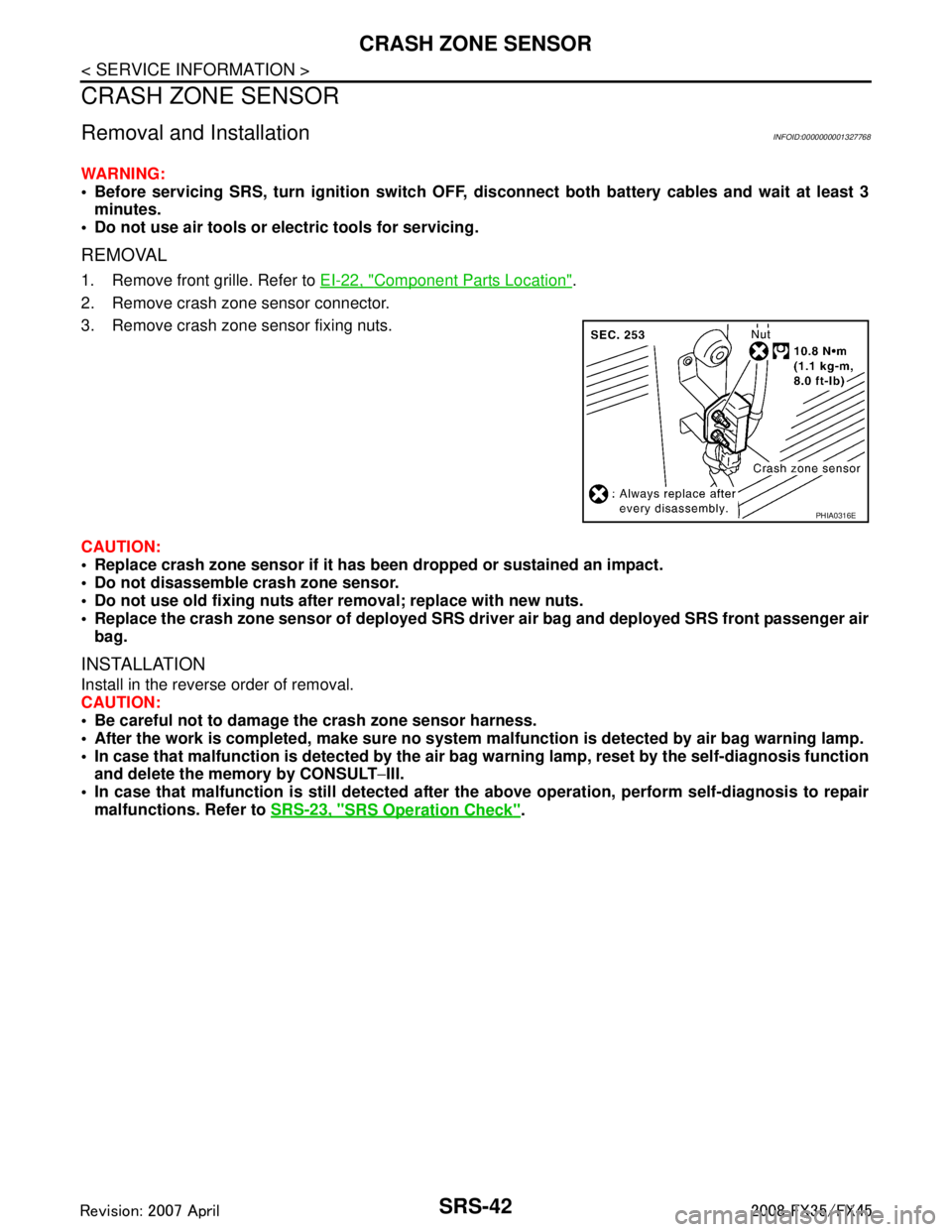
1. Remove front grille. Refer to EI-22, "Component Parts Location".
2. Remove crash zone sensor connector.
3. Remove crash zone sensor fixing nuts.
CAUTION:
Replace crash zone sensor if it has b een dropped or sustained an impact.
Do not disassemble crash zone sensor.
Do not use old fixing nuts afte r removal; replace with new nuts.
Replace the crash zone sensor of deployed SRS dr iver air bag and deployed SRS front passenger air
bag.
INSTALLATION
Install in the reverse order of removal.
CAUTION:
Be careful not to damage the crash zone sensor harness.
After the work is completed, make sure no system malfunction is detected by air bag warning lamp.
In case that malfunction is detected by the air ba g warning lamp, reset by the self-diagnosis function
and delete the memory by CONSULT −III.
In case that malfunction is still de tected after the above operation, perform self-diagnosis to repair
malfunctions. Refer to SRS-23, "
SRS Operation Check".
PHIA0316E
3AA93ABC3ACD3AC03ACA3AC03AC63AC53A913A773A893A873A873A8E3A773A983AC73AC93AC03AC3
3A893A873A873A8F3A773A9D3AAF3A8A3A8C3A863A9D3AAF3A8B3A8C
Page 3780 of 3924
SIDE AIR BAG (SATELLITE) SENSOR
SRS-43
< SERVICE INFORMATION >
C
D E
F
G
I
J
K L
M A
B
SRS
N
O P
SIDE AIR BAG (S ATELLITE) SENSOR
Removal and InstallationINFOID:0000000001327769
WARNING:
Before servicing SRS, turn igniti on switch OFF, disconnect both ba ttery cables and wait at least 3
minutes.
Do not use air tools or el ectric tools for servicing.
REMOVAL
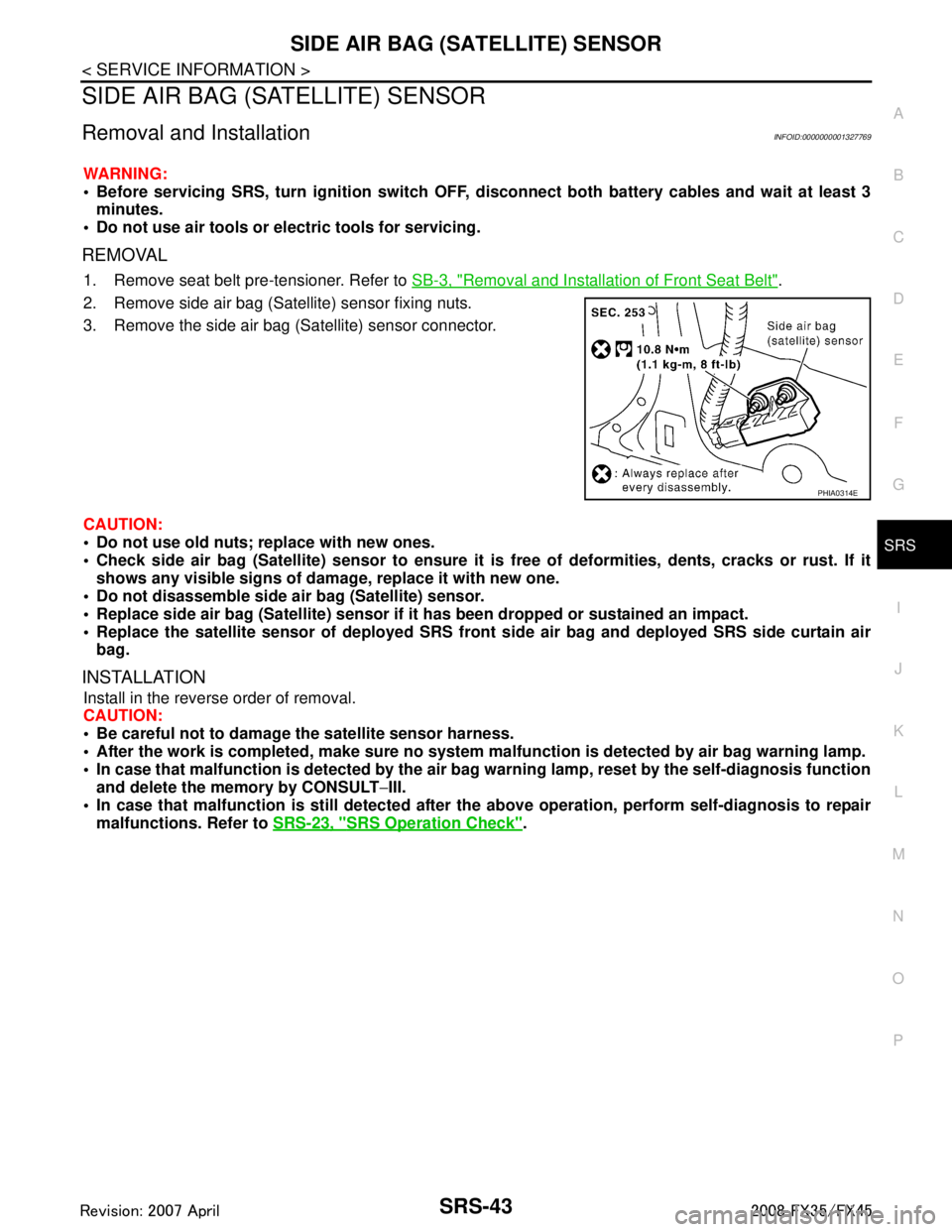
1. Remove seat belt pre-tensioner. Refer to SB-3, "Removal and Installation of Front Seat Belt".
2. Remove side air bag (Satellite) sensor fixing nuts.
3. Remove the side air bag (Satellite) sensor connector.
CAUTION:
Do not use old nuts; replace with new ones.
Check side air bag (Satellite) senso r to ensure it is free of deformities, dents, cracks or rust. If it
shows any visible signs of da mage, replace it with new one.
Do not disassemble side ai r bag (Satellite) sensor.
Replace side air bag (Satellite) sensor if it has been dropped or sustained an impact.
Replace the satellite sensor of de ployed SRS front side air bag and deployed SRS side curtain air
bag.
INSTALLATION
Install in the reverse order of removal.
CAUTION:
Be careful not to damage the satellite sensor harness.
After the work is completed, make sure no system malfunction is detected by air bag warning lamp.
In case that malfunction is detected by the air ba g warning lamp, reset by the self-diagnosis function
and delete the memory by CONSULT −III.
In case that malfunction is still detected after th e above operation, perform self-diagnosis to repair
malfunctions. Refer to SRS-23, "
SRS Operation Check".
PHIA0314E
3AA93ABC3ACD3AC03ACA3AC03AC63AC53A913A773A893A873A873A8E3A773A983AC73AC93AC03AC3
3A893A873A873A8F3A773A9D3AAF3A8A3A8C3A863A9D3AAF3A8B3A8C
Page 3781 of 3924
SRS-44
< SERVICE INFORMATION >
DIAGNOSIS SENSOR UNIT
DIAGNOSIS SENSOR UNIT
Removal and InstallationINFOID:0000000001327771
WARNING:
Before servicing SRS, turn ignition switch OFF, disconnect both ba ttery cables and wait at least 3
minutes.
Do not use air tools or el ectric tools for servicing.
REMOVAL
1. Disconnect each harness connector for the ai r bag module and seat belt pre-tensioner.
2. Remove center console. Refer to IP-11, "
Removal and Installation".
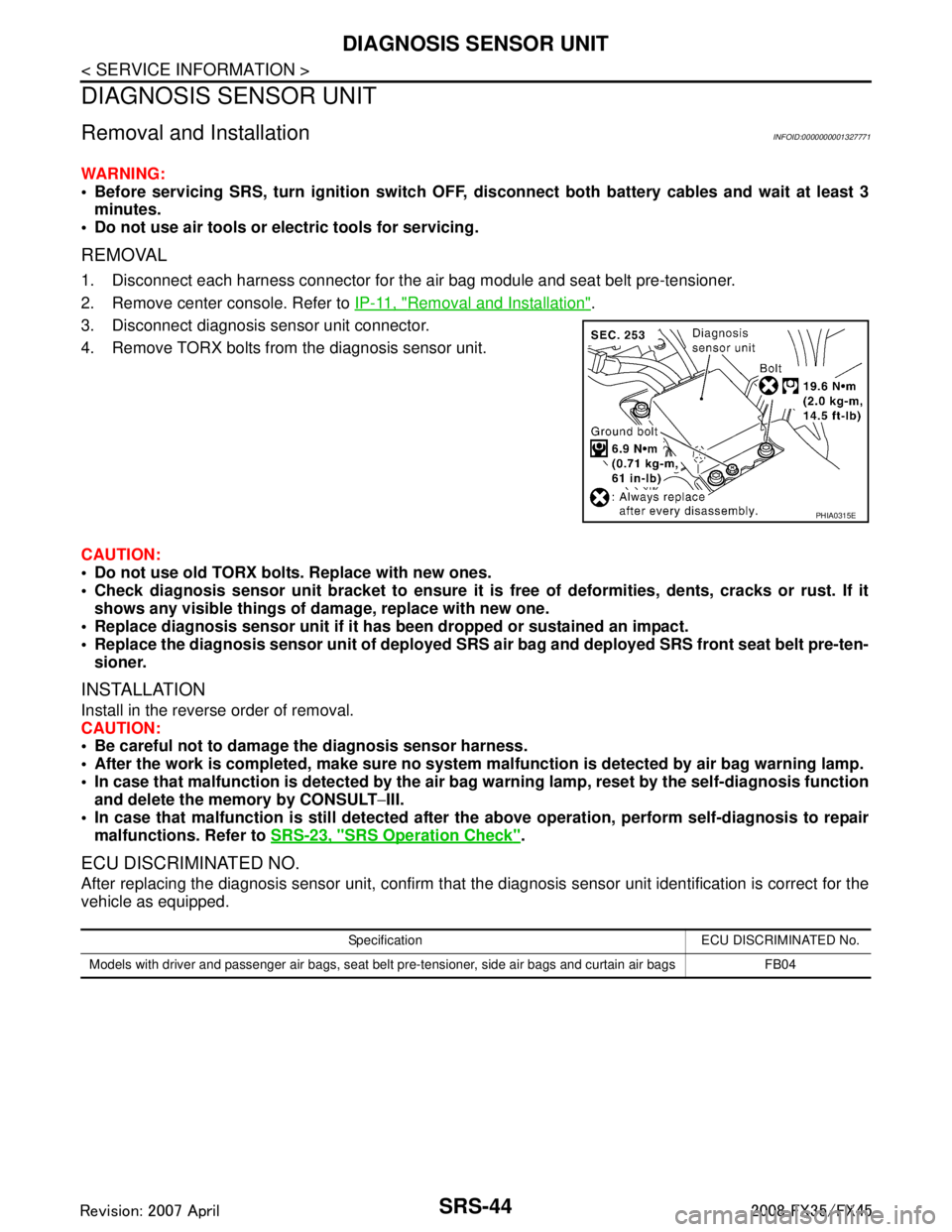
3. Disconnect diagnosis sensor unit connector.
4. Remove TORX bolts from the diagnosis sensor unit.
CAUTION:
Do not use old TORX bolts. Replace with new ones.
Check diagnosis sensor unit bracket to ensure it is free of deformities, dents, cracks or rust. If it
shows any visible things of damage, replace with new one.
Replace diagnosis sensor unit if it has been dropped or sustained an impact.
Replace the diagnosis sensor unit of deployed SRS air bag and deployed SRS front seat belt pre-ten-
sioner.
INSTALLATION
Install in the reverse order of removal.
CAUTION:
Be careful not to damage the diagnosis sensor harness.
After the work is completed, make sure no system malfunction is detected by air bag warning lamp.
In case that malfunction is detected by the air ba g warning lamp, reset by the self-diagnosis function
and delete the memory by CONSULT −III.
In case that malfunction is still de tected after the above operation, perform self-diagnosis to repair
malfunctions. Refer to SRS-23, "
SRS Operation Check".
ECU DISCRIMINATED NO.
After replacing the diagnosis sensor unit, confirm that t he diagnosis sensor unit identification is correct for the
vehicle as equipped.
PHIA0315E
Specification ECU DISCRIMINATED No.
Models with driver and passenger air bags, seat belt pre-tensioner, side air bags and curtain air bags FB04
3AA93ABC3ACD3AC03ACA3AC03AC63AC53A913A773A893A873A873A8E3A773A983AC73AC93AC03AC3
3A893A873A873A8F3A773A9D3AAF3A8A3A8C3A863A9D3AAF3A8B3A8C
Page 3784 of 3924
COLLISION DIAGNOSISSRS-47
< SERVICE INFORMATION >
C
DE
F
G
I
J
K L
M A
B
SRS
N
O P
COLLISION DIAGNOSIS
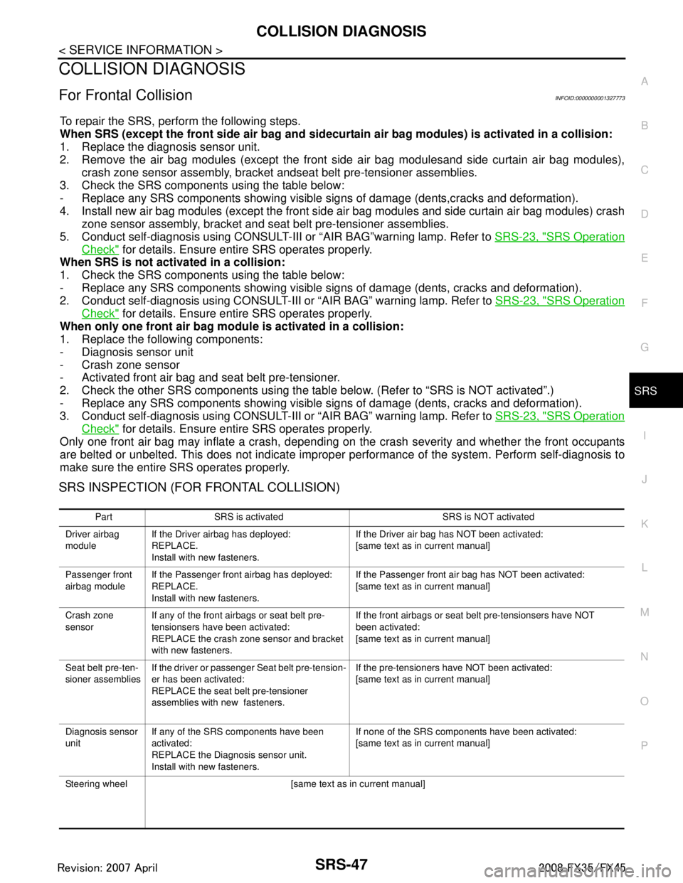
For Frontal CollisionINFOID:0000000001327773
To repair the SRS, perform the following steps.
When SRS (except the front side air bag and sidecurt ain air bag modules) is activated in a collision:
1. Replace the diagnosis sensor unit.
2. Remove the air bag modules (except the front side air bag modulesand side curtain air bag modules),
crash zone sensor assembly, bracket andseat belt pre-tensioner assemblies.
3. Check the SRS components using the table below:
- Replace any SRS components showing visible signs of damage (dents,cracks and deformation).
4. Install new air bag modules (except the front side air bag modules and side curtain air bag modules) crash
zone sensor assembly, bracket and seat belt pre-tensioner assemblies.
5. Conduct self-diagnosis using CONSULT-III or “AIR BAG”warning lamp. Refer to SRS-23, "
SRS Operation
Check" for details. Ensure entire SRS operates properly.
When SRS is not acti vated in a collision:
1. Check the SRS components using the table below:
- Replace any SRS components showing visible signs of damage (dents, cracks and deformation).
2. Conduct self-diagnosis using CONSULT-III or “AIR BAG” warning lamp. Refer to SRS-23, "
SRS Operation
Check" for details. Ensure entire SRS operates properly.
When only one front air bag modu le is activated in a collision:
1. Replace the following components:
- Diagnosis sensor unit
- Crash zone sensor
- Activated front air bag and seat belt pre-tensioner.
2. Check the other SRS components using the table below. (Refer to “SRS is NOT activated”.)
- Replace any SRS components showing visible signs of damage (dents, cracks and deformation).
3. Conduct self-diagnosis using CONSULT-III or “AIR BAG” warning lamp. Refer to SRS-23, "
SRS Operation
Check" for details. Ensure entire SRS operates properly.
Only one front air bag may inflate a crash, depending on t he crash severity and whether the front occupants
are belted or unbelted. This does not indicate improper performance of the system. Perform self-diagnosis to
make sure the entire SRS operates properly.
SRS INSPECTION (FOR FRONTAL COLLISION)
Part SRS is activated SRS is NOT activated
Driver airbag
module If the Driver airbag has deployed:
REPLACE.
Install with new fasteners. If the Driver air bag has NOT been activated:
[same text as in current manual]
Passenger front
airbag module If the Passenger front airbag has deployed:
REPLACE.
Install with new fasteners. If the Passenger front air bag has NOT been activated:
[same text as in current manual]
Crash zone
sensor If any of the front airbags or seat belt pre-
tensionsers have been activated:
REPLACE the crash zone sensor and bracket
with new fasteners. If the front airbags or seat belt pre-tensionsers have NOT
been activated:
[same text as in current manual]
Seat belt pre-ten-
sioner assemblies If the driver or passenger Seat belt pre-tension-
er has been activated:
REPLACE the seat belt pre-tensioner
assemblies with new fasteners. If the pre-tensioners have NOT been activated:
[same text as in current manual]
Diagnosis sensor
unit If any of the SRS components have been
activated:
REPLACE the Diagnosis sensor unit.
Install with new fasteners. If none of the SRS components have been activated:
[same text as in current manual]
Steering wheel [same text as in current manual]
3AA93ABC3ACD3AC03ACA3AC03AC63AC53A913A773A893A873A873A8E3A773A983AC73AC93AC03AC3
3A893A873A873A8F3A773A9D3AAF3A8A3A8C3A863A9D3AAF3A8B3A8C
Page 3785 of 3924
SRS-48
< SERVICE INFORMATION >
COLLISION DIAGNOSIS
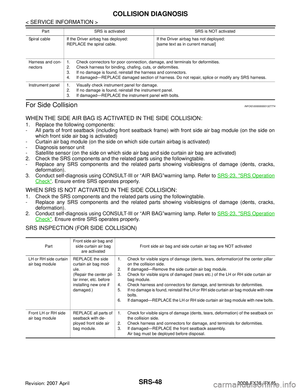
For Side Collision
INFOID:0000000001327774
WHEN THE SIDE AIR BAG IS ACTIVATED IN THE SIDE COLLISION:
1. Replace the following components:
- All parts of front seatback (including front seatba ck frame) with front side air bag module (on the side on
which front side air bag is activated)
- Curtain air bag module (on the side on which side curtain airbag is activated)
- Diagnosis sensor unit
- Satellite sensor (on the side on which side air bag and side curtain air bag are activated)
2. Check the SRS components and the related parts using the followingtable.
- Replace any SRS components and the related parts showing visiblesigns of damage (dents, cracks, deformation).
3. Conduct self-diagnosis using CONSULT-III or “AIR BAG”warning lamp. Refer to SRS-23, "
SRS Operation
Check". Ensure entire SRS operates properly.
WHEN SRS IS NOT ACTIVATED IN THE SIDE COLLISION:
1. Check the SRS components and the related parts using the followingtable.
- Replace any SRS components and the related parts showing visiblesigns of damage (dents, cracks,
deformation).
2. Conduct self-diagnosis using CONSULT-III or “AIR BAG”warning lamp. Refer to SRS-23, "
SRS Operation
Check". Ensure entire SRS operates properly.
SRS INSPECTION (FOR SIDE COLLISION)
Spiral cable If the Driver airbag has deployed:
REPLACE the spiral cable. If the Driver airbag has not deployed:
[same text as in current manual]
Harness and con-
nectors 1. Check connectors for poor connection, damage, and terminals for deformities.
2. Check harness for binding, chafing, cuts, or deformities.
3. If no damage is found, reinstall the harness and connectors.
4. If damaged—REPLACE damaged section of harness. Do not repair, splice or modify any SRS harness.
Instrument panel 1. Visually check instrument panel for damage. 2. If no damage is found, reinstall the instrument panel.
3. If damaged—REPLACE the instrument panel with bolts.
Part SRS is activated SRS is NOT activated
Part
Front side air bag and
side curtain air bag are activated Front side air bag and side curtain air bag are NOT activated
LH or RH side curtain
air bag module REPLACE the side
curtain air bag mod-
ule.
(Repair the center pil-
lar inner, etc. before
installing new one if
damaged.)1. Check for visible signs of damage (dents, tears, deformation)of the center pillar
on the collision side.
2. If damaged—Remove the side curtain air bag module.
3. Check for visible signs of damaged (tears etc.) of the LH or RH side curtain air bag module.
4. Check harness and connectors for damage, and terminals for deformities.
5. If no damage is found, reinstall the LH or RH side curtain air bag module with new bolts.
6. If damaged—REPLACE the LH or RH side curtain air bag module with new bolts.
Front LH or RH side
air bag module REPLACE all parts of
seatback with de-
ployed front side air
bag module.1. Check for visible signs of damage (dents, tears, deformation) of the seatback on
the collision side.
2. Check harness and connectors for damage, and terminals for deformities.
3. If damaged—REPLACE the front seatback assembly. Air bag must be deployed before disposal.
3AA93ABC3ACD3AC03ACA3AC03AC63AC53A913A773A893A873A873A8E3A773A983AC73AC93AC03AC3
3A893A873A873A8F3A773A9D3AAF3A8A3A8C3A863A9D3AAF3A8B3A8C
Page 3787 of 3924

TF-1
DRIVELINE/AXLE
CEF
G H
I
J
K L
M
SECTION TF
A
B
TF
N
O P
CONTENTS
TRANSFER
SERVICE INFORMATION .. ..........................3
DTC INDEX ..................................................... .....3
C1201-C1210, U1000 ......................................... ......3
PRECAUTIONS ...................................................4
Precaution for Supplemental Restraint System
(SRS) "AIR BAG" and "SEAT BELT PRE-TEN-
SIONER" ............................................................. ......
4
Precaution .................................................................4
Service Notice or Precaution .....................................5
PREPARATION ...................................................6
Special Service Tool ........................................... ......6
Commercial Service Tool ..........................................7
NOISE, VIBRATION AND HARSHNESS
(NVH) TROUBLESHOOTING .............................
9
NVH Troubleshooting Chart ................................ ......9
TRANSFER FLUID .............................................10
Replacement ....................................................... ....10
Inspection ................................................................10
AWD SYSTEM ................................................ ....11
Power Transfer Diagram ..................................... ....11
System Description .................................................11
Schematic ...............................................................13
CAN Communication ...............................................13
TROUBLE DIAGNOSIS .....................................14
Fail-Safe Function ............................................... ....14
How to Perform Trouble Diagnosis .........................14
Location of Electrical Parts ......................................15
Circuit Diagram .......................................................16
Wiring Diagram - AWD - ..........................................17
Trouble Diagnosis Chart by Symptom ....................20
AWD Control Unit Input/Output Signal Reference
Value ................................................................... ....
20
CONSULT-III Function (ALL MODE AWD/4WD) ....21
TROUBLE DIAGNOSIS FOR SYSTEM .............24
DTC C1201 CONTROLLER FAILURE ................ ....24
DTC C1203 ABS SYSTEM ......................................24
DTC C1204 4WD SOLENOID ............................. ....25
DTC C1205 4WD ACTUATOR RLY ........................27
DTC C1210 ENGINE SIGNAL 1 ..............................28
DTC U1000 CAN COMM CIRCUIT .........................28
Power Supply Circuit for AWD Control Unit .............28
TROUBLE DIAGNOSIS FOR SYMPTOMS ......30
AWD Warning Lamp Does Not Turn ON When the
Ignition Switch Is Turned to ON ...............................
30
AWD Warning Lamp Does Not Turn OFF Several
Seconds after Engine Started ..................................
30
Heavy Tight-Corner Braking Symptom Occurs
When the Vehicle Is Driven and the Steering
Wheel Is Turned Fully to Either Side after the En-
gine Is Started .........................................................
32
Vehicle Does Not Enter AWD Mode Even Though
AWD Warning Lamp Turned to OFF .......................
33
While Driving, AWD Warning Lamp Flashes Rap-
idly (When Flashing in Approx. 1 Minute and Then
Turning OFF) ....................................................... ....
33
While Driving, AWD Warning Lamp Flashes Slow-
ly (When Continuing to Flash until Turning Ignition
Switch OFF) .............................................................
33
AWD CONTROL UNIT ......................................35
Removal and Installation .........................................35
FRONT OIL SEAL .............................................36
Removal and Installation .........................................36
REAR OIL SEAL ...............................................37
Removal and Installation .........................................37
AIR BREATHER HOSE ....................................39
Removal and Installation .........................................39
TRANSFER ASSEMBLY ..................................40
Removal and Installation .........................................40
Disassembly and Assembly .....................................40
3AA93ABC3ACD3AC03ACA3AC03AC63AC53A913A773A893A873A873A8E3A773A983AC73AC93AC03AC3
3A893A873A873A8F3A773A9D3AAF3A8A3A8C3A863A9D3AAF3A8B3A8C
Page 3790 of 3924

TF-4
< SERVICE INFORMATION >
PRECAUTIONS
PRECAUTIONS
Precaution for Supplemental Restraint System (SRS) "AIR BAG" and "SEAT BELT
PRE-TENSIONER"
INFOID:0000000001612930
The Supplemental Restraint System such as “A IR BAG” and “SEAT BELT PRE-TENSIONER”, used along
with a front seat belt, helps to reduce the risk or severi ty of injury to the driver and front passenger for certain
types of collision. This system includes seat belt switch inputs and dual stage front air bag modules. The SRS
system uses the seat belt switches to determine the front air bag deployment, and may only deploy one front
air bag, depending on the severity of a collision and w hether the front occupants are belted or unbelted.
Information necessary to service the system safely is included in the “SUPPLEMENTAL RESTRAINT SYS-
TEM” and “SEAT BELTS” of this Service Manual.
WARNING:
• To avoid rendering the SRS inopera tive, which could increase the risk of personal injury or death in
the event of a collision which would result in air bag inflation, all maintenance must be performed by
an authorized NISS AN/INFINITI dealer.
Improper maintenance, including in correct removal and installation of the SRS, can lead to personal
injury caused by unintent ional activation of the system. For re moval of Spiral Cable and Air Bag
Module, see the “SUPPLEMEN TAL RESTRAINT SYSTEM”.
Do not use electrical test equipmen t on any circuit related to the SRS unless instructed to in this
Service Manual. SRS wiring harnesses can be identi fied by yellow and/or orange harnesses or har-
ness connectors.
PrecautionINFOID:0000000001327424
Before connecting or disconnect ing the AWD control unit har-
ness connector, turn ignition switch “OFF” and disconnect
battery ground cable. Because battery voltage is applied to
AWD control unit even if igni tion switch is turned “OFF”.
When connecting or disconnect ing pin connectors into or
from AWD control unit, take care not to damage pin terminals
(bend or break).
When connecting pin connectors, make sure that there are no
bends or breaks on AWD control unit pin terminal.
SEF289H
SEF291H
3AA93ABC3ACD3AC03ACA3AC03AC63AC53A913A773A893A873A873A8E3A773A983AC73AC93AC03AC3
3A893A873A873A8F3A773A9D3AAF3A8A3A8C3A863A9D3AAF3A8B3A8C