2008 INFINITI FX35 hood open
[x] Cancel search: hood openPage 2081 of 3924
DTC P0138, P0158 HO2S2EC-841
< SERVICE INFORMATION > [VK45DE]
C
D
E
F
G H
I
J
K L
M A
EC
NP
O
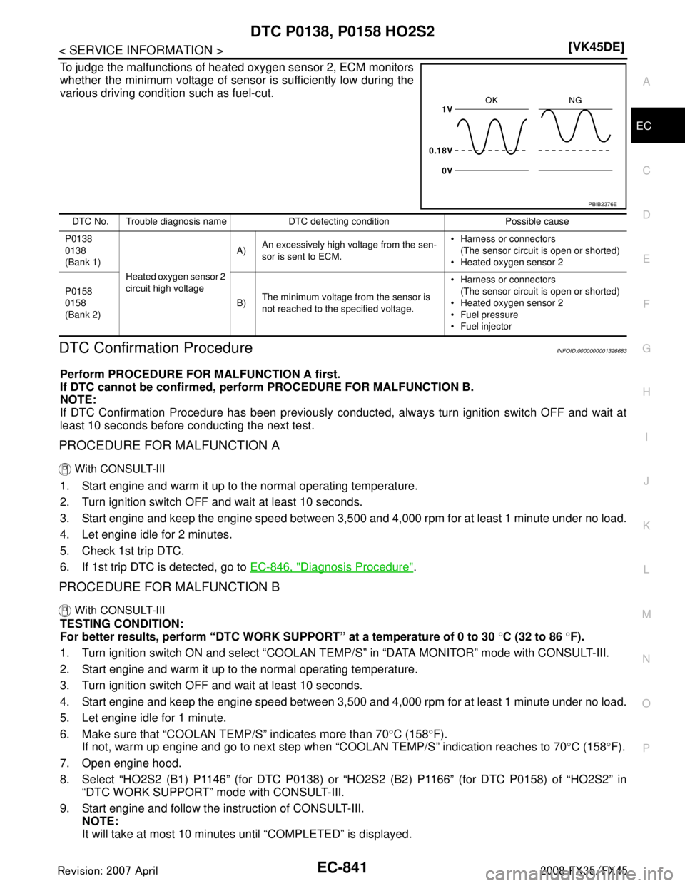
To judge the malfunctions of heated oxygen sensor 2, ECM monitors
whether the minimum voltage of sensor is sufficiently low during the
various driving condition such as fuel-cut.
DTC Confirmation ProcedureINFOID:0000000001326683
Perform PROCEDURE FOR MALFUNCTION A first.
If DTC cannot be confirmed, perform PROCEDURE FOR MALFUNCTION B.
NOTE:
If DTC Confirmation Procedure has been previously conduc
ted, always turn ignition switch OFF and wait at
least 10 seconds before conducting the next test.
PROCEDURE FOR MALFUNCTION A
With CONSULT-III
1. Start engine and warm it up to the normal operating temperature.
2. Turn ignition switch OFF and wait at least 10 seconds.
3. Start engine and keep the engine speed between 3,500 and 4,000 rpm for at least 1 minute under no load.
4. Let engine idle for 2 minutes.
5. Check 1st trip DTC.
6. If 1st trip DTC is detected, go to EC-846, "
Diagnosis Procedure".
PROCEDURE FOR MALFUNCTION B
With CONSULT-III
TESTING CONDITION:
For better results, perform “DTC WORK SUPPORT” at a temperature of 0 to 30 °C (32 to 86 °F).
1. Turn ignition switch ON and select “COOLAN TEMP/S” in “DATA MONITOR” mode with CONSULT-III.
2. Start engine and warm it up to the normal operating temperature.
3. Turn ignition switch OFF and wait at least 10 seconds.
4. Start engine and keep the engine speed between 3,500 and 4,000 rpm for at least 1 minute under no load.
5. Let engine idle for 1 minute.
6. Make sure that “COOLAN TEMP/S” indicates more than 70 °C (158 °F).
If not, warm up engine and go to next step when “COOLAN TEMP/S” indication reaches to 70°C (158 °F).
7. Open engine hood.
8. Select “HO2S2 (B1) P1146” (for DTC P0138) or “HO2S2 (B2) P1166” (for DTC P0158) of “HO2S2” in
“DTC WORK SUPPORT” mode with CONSULT-III.
9. Start engine and follow the instruction of CONSULT-III. NOTE:
It will take at most 10 minutes until “COMPLETED” is displayed.
PBIB2376E
DTC No. Trouble diagnosis name DTC detecting condition Possible cause
P0138
0138
(Bank 1) Heated oxygen sensor 2
circuit high voltage A)
An excessively high voltage from the sen-
sor is sent to ECM. Harness or connectors
(The sensor circuit is open or shorted)
Heated oxygen sensor 2
P0158
0158
(Bank 2) B)
The minimum voltage from the sensor is
not reached to the specified voltage. Harness or connectors
(The sensor circuit is open or shorted)
Heated oxygen sensor 2
Fuel pressure
Fuel injector
3AA93ABC3ACD3AC03ACA3AC03AC63AC53A913A773A893A873A873A8E3A773A983AC73AC93AC03AC3
3A893A873A873A8F3A773A9D3AAF3A8A3A8C3A863A9D3AAF3A8B3A8C
Page 2157 of 3924
DTC P0420, P0430 THREE WAY CATALYST FUNCTION
EC-917
< SERVICE INFORMATION > [VK45DE]
C
D
E
F
G H
I
J
K L
M A
EC
NP
O
DTC P0420, P0430 THREE WAY CATALYST FUNCTION
On Board Diagnosis LogicINFOID:0000000001326754
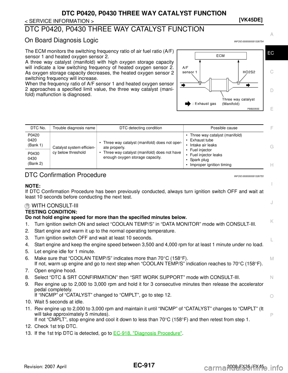
The ECM monitors the switching frequency ratio of air fuel ratio (A/F)
sensor 1 and heated oxygen sensor 2.
A three way catalyst (manifold) with high oxygen storage capacity
will indicate a low switching frequency of heated oxygen sensor 2.
As oxygen storage capacity decr
eases, the heated oxygen sensor 2
switching frequency will increase.
When the frequency ratio of A/F sensor 1 and heated oxygen sensor
2 approaches a specified limit value, the three way catalyst (mani-
fold) malfunction is diagnosed.
DTC Confirmation ProcedureINFOID:0000000001326755
NOTE:
If DTC Confirmation Procedure has been previously conduc ted, always turn ignition switch OFF and wait at
least 10 seconds before conducting the next test.
WITH CONSULT-III
TESTING CONDITION:
Do not hold engine speed for more than the specified minutes below.
1. Turn ignition switch ON and select “COOLAN TEMP/S” in “DATA MONITOR” mode with CONSULT-III.
2. Start engine and warm it up to the normal operating temperature.
3. Turn ignition switch OFF and wait at least 10 seconds.
4. Start engine and keep the engine speed between 3,500 and 4,000 rpm for at least 1 minute under no load.
5. Let engine idle for 1 minute.
6. Make sure that “COOLAN TEMP/S” indicates more than 70 °C (158 °F).
If not, warm up engine and go to next step when “COOLAN TEMP/S” indication reaches to 70°C (158 °F).
7. Open engine hood.
8. Select “DTC & SRT CONFIRMATION” then “SRT WORK SUPPORT” mode with CONSULT-III.
9. Rev engine up to 2,000 to 3,000 rpm and hold it for 3 consecutive minutes then release the accelerator pedal completely.
If “INCMP” of “CATALYST” changed to “CMPLT”, go to step 12.
10. Wait 5 seconds at idle.
11. Rev engine up to 2,000 to 3,000 rpm and maintain it unt il “INCMP” of “CATALYST” changes to “CMPLT” (It
will take approximately 5 minutes).
If not “CMPLT”, stop engine and cool it down to less than 70 °C (158 °F) and then retest from step 1.
12. Check 1st trip DTC.
13. If the 1st trip DTC is detected, go to EC-918, "
Diagnosis Procedure".
PBIB2055E
DTC No. Trouble diagnosis name DTC detecting condition Possible cause
P0420
0420
(Bank 1) Catalyst system efficien-
cy below threshold Three way catalyst (manifold) does not oper-
ate properly.
Three way catalyst (manifold) does not have enough oxygen storage capacity. Three way catalyst (manifold)
Exhaust tube
Intake air leaks
Fuel injector
Fuel injector leaks
Spark plug
Improper ignition timing
P0430
0430
(Bank 2)
3AA93ABC3ACD3AC03ACA3AC03AC63AC53A913A773A893A873A873A8E3A773A983AC73AC93AC03AC3
3A893A873A873A8F3A773A9D3AAF3A8A3A8C3A863A9D3AAF3A8B3A8C
Page 2158 of 3924
EC-918
< SERVICE INFORMATION >[VK45DE]
DTC P0420, P0430 THREE
WAY CATALYST FUNCTION
Overall Function Check
INFOID:0000000001326756
Use this procedure to check the overall function of the th ree way catalyst (manifold). During this check, a 1st
trip DTC might not be confirmed.
WITH GST
1. Start engine and warm it up to the normal operating temperature.
2. Turn ignition switch OFF and wait at least 10 seconds.
3. Start engine and keep the engine speed between 3,500 and 4,000 rpm for at least 1 minute under no load.
4. Let engine idle for 1 minute.
5. Open engine hood.
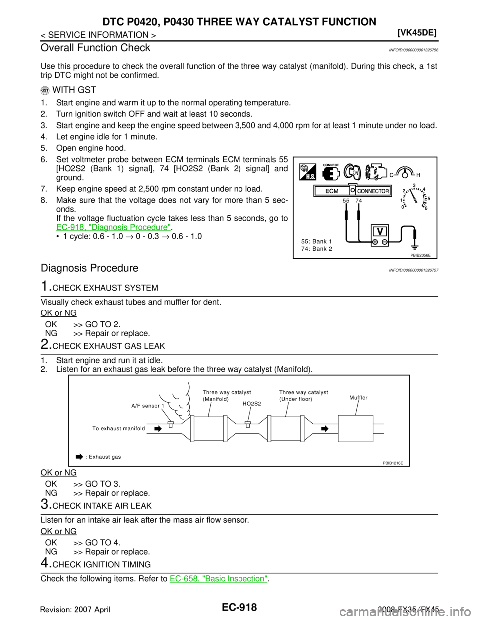
6. Set voltmeter probe between ECM terminals ECM terminals 55 [HO2S2 (Bank 1) signal], 74 [HO2S2 (Bank 2) signal] and
ground.
7. Keep engine speed at 2,500 rpm constant under no load.
8. Make sure that the voltage does not vary for more than 5 sec- onds.
If the voltage fluctuation cycle takes less than 5 seconds, go to
EC-918, "
Diagnosis Procedure".
1 cycle: 0.6 - 1.0 → 0 - 0.3 → 0.6 - 1.0
Diagnosis ProcedureINFOID:0000000001326757
1.CHECK EXHAUST SYSTEM
Visually check exhaust tubes and muffler for dent.
OK or NG
OK >> GO TO 2.
NG >> Repair or replace.
2.CHECK EXHAUST GAS LEAK
1. Start engine and run it at idle.
2. Listen for an exhaust gas leak before the three way catalyst (Manifold).
OK or NG
OK >> GO TO 3.
NG >> Repair or replace.
3.CHECK INTAKE AIR LEAK
Listen for an intake air leak after the mass air flow sensor.
OK or NG
OK >> GO TO 4.
NG >> Repair or replace.
4.CHECK IGNITION TIMING
Check the following items. Refer to EC-658, "
Basic Inspection".
PBIB2056E
PBIB1216E
3AA93ABC3ACD3AC03ACA3AC03AC63AC53A913A773A893A873A873A8E3A773A983AC73AC93AC03AC3
3A893A873A873A8F3A773A9D3AAF3A8A3A8C3A863A9D3AAF3A8B3A8C
Page 2214 of 3924
EC-974
< SERVICE INFORMATION >[VK45DE]
DTC P0455 EVAP CONTROL SYSTEM
Make sure that EVAP hoses are connected to EVAP canister purge volume control solenoid valve
properly.
If DTC Confirmation Procedure has been previously conduc ted, always turn ignition switch OFF and wait at
least 10 seconds before conducting the next test.
TESTING CONDITION:
Perform “DTC WORK SUPPORT” when the fuel level is between 1/4 and 3/4 full, and vehicle is placed
on flat level surface.
Open engine hood before conducting the following procedures.
WITH CONSULT-III
1. Tighten fuel filler cap secure ly until ratcheting sound is heard.
2. Turn ignition switch ON.
3. Turn ignition switch OFF and wait at least 10 seconds.
4. Turn ignition switch ON and select “DATA MONITOR” mode with CONSULT-III.
5. Make sure that the following conditions are met. COOLAN TEMP/S: 0 - 70 °C (32 - 158 °F)
INT/A TEMP SE: 0 - 60 °C (32 - 140 °F)
6. Select “EVAP SML LEAK P0442/P1442” of “EV APORATIVE SYSTEM” in “DTC WORK SUPPORT” mode
with CONSULT-III.
Follow the instruction displayed.
NOTE:
If the engine speed cannot be maintained within t he range displayed on the CONSULT-III screen, go to
EC-658, "
Basic Inspection".
7. Make sure that “OK” is displayed. If “NG” is displayed, select “SELF-DIAG RE SULTS” mode and make sure that “EVAP GROSS LEAK
[P0455]” is displayed. If it is displayed, refer to EC-974, "
Diagnosis Procedure".
If P0442 is displayed, perform Diagnostic Procedure for DTC P0442 EC-927, "
Diagnosis Procedure".
WITH GST
NOTE:
Be sure to read the explanation of EC-633, "
Emission-related Diagnostic Information" before driving vehicle.
1. Start engine.
2. Drive vehicle according to EC-633, "
Emission-related Diagnostic Information".
3. Stop vehicle.
4. Turn ignition switch OFF, wait at least 10 seconds and then turn ON.
5. Select “Service $07” with GST. If P0455 is displayed on the screen, go to EC-974, "
Diagnosis Procedure".
If P0442 is displayed on the screen, go to EC-927, "
Diagnosis Procedure".
If P0441 is displayed on the screen, go to EC-922, "
Diagnosis Procedure".
Diagnosis ProcedureINFOID:0000000001326818
1.CHECK FUEL FILLER CAP DESIGN
1. Turn ignition switch OFF.
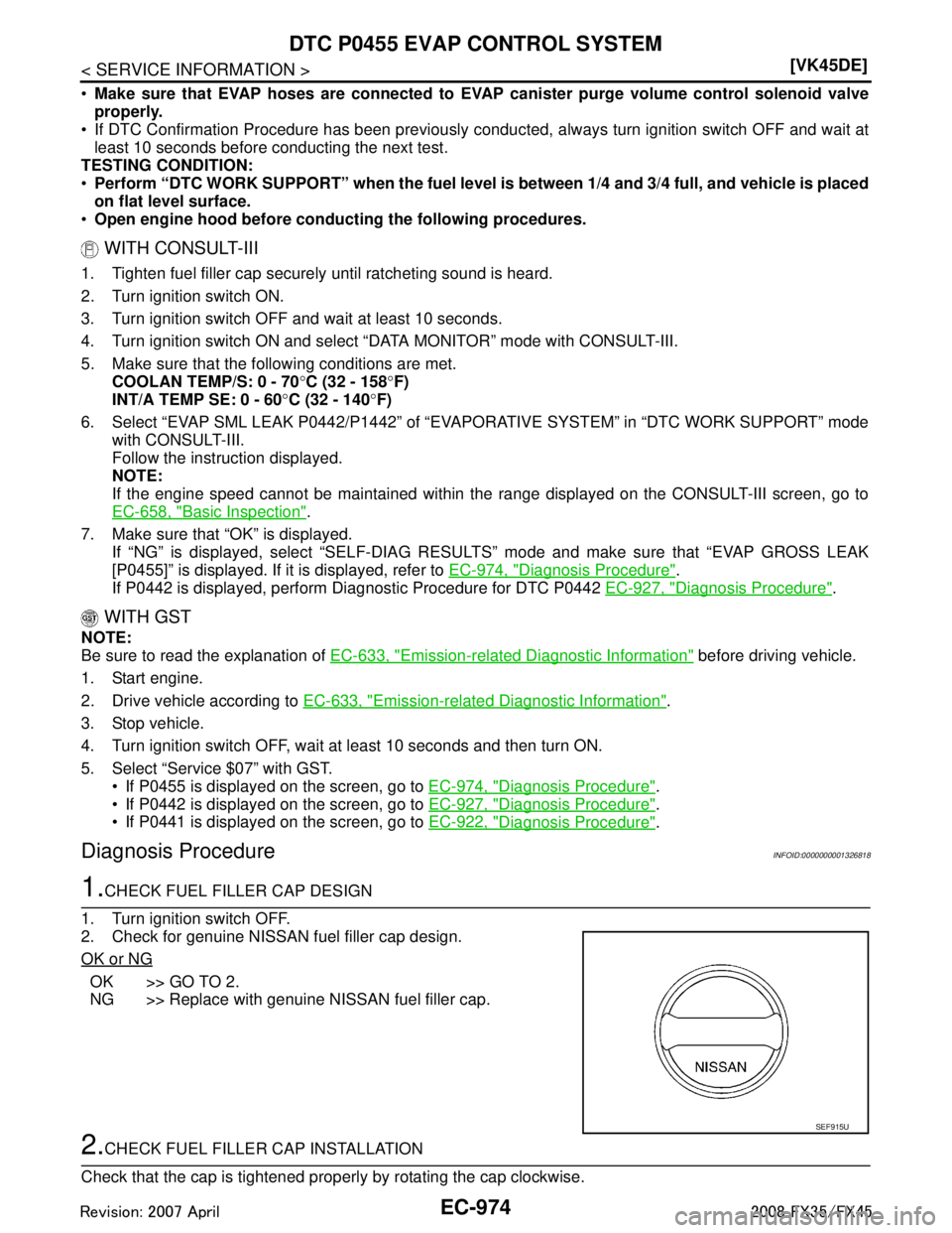
2. Check for genuine NISSAN fuel filler cap design.
OK or NG
OK >> GO TO 2.
NG >> Replace with genuine NISSAN fuel filler cap.
2.CHECK FUEL FILLER CAP INSTALLATION
Check that the cap is tightened proper ly by rotating the cap clockwise.
SEF915U
3AA93ABC3ACD3AC03ACA3AC03AC63AC53A913A773A893A873A873A8E3A773A983AC73AC93AC03AC3
3A893A873A873A8F3A773A9D3AAF3A8A3A8C3A863A9D3AAF3A8B3A8C
Page 2220 of 3924
EC-980
< SERVICE INFORMATION >[VK45DE]
DTC P0456 EVAP CONTROL SYSTEM
DTC Confirmation Procedure
INFOID:0000000001326820
NOTE:
If DTC P0456 is displayed with P0442, firs t perform trouble diagnosis for DTC P0456.
After repair, make sure that the hoses and clips are installed properly.
If DTC Confirmation Procedure has been previously conduc ted, always turn ignition switch OFF and wait at
least 10 seconds before conducting the next test.
TESTING CONDITION:
Open engine hood before conducting following procedure.
If any of following conditions are met just befo re the DTC confirmation procedure, leave the vehicle
for more than 1 hour.
- Fuel filler cap is removed.
- Fuel is refilled or drained.
- EVAP component parts is/are removed.
Before performing the following procedure, confirm that battery voltage is more than 11V at idle.
WITH CONSULT-III
1. Turn ignition switch ON and select “DATA MONITOR” mode with CONSULT-III.
2. Make sure the following conditions are met.
FUEL LEVEL SE: 0.25 - 1.4V
COOLAN TEMP/S: 0 - 32 °C (32 - 90 °F)
FUEL T/TMP SE: 0 - 35 °C (32 - 95 °F)
INT/A TEMP SE: More than 0 °C (32 °F)
If NG, turn ignition switch OFF and leave the vehicle in a cool place (soak the vehicle) or refilling/draining
fuel until the output voltage condition of the “FUE L LEVEL SE” meets within the range above and leave
the vehicle for more than 1 hour. Then start from step 1).
3. Turn ignition switch OFF and wait at least 10 seconds.
4. Turn ignition switch ON.
5. Select “EVAP V/S LEAK P0456/P1456” of “EVAPO RATIVE SYSTEM” in “DTC WORK SUPPORT” mode
with CONSULT-III.
Follow the instruction displayed.
6. Make sure that “OK” is displayed. If “NG” is displayed, refer to EC-981, "
Diagnosis Procedure".
NOTE:
If the engine speed cannot be maintained with in the range displayed on CONSULT-III screen, go
to EC-658, "
Basic Inspection".
Make sure that EVAP hoses are connected to EVAP canister purge volume control solenoid
valve properly.
Overall Function CheckINFOID:0000000001326821
WITH GST
Use this procedure to check the overall function of the EV AP very small leak function. During this check, a 1st
trip DTC might not be confirmed.
CAUTION:
Do not use compressed air, doing so may damage the EVAP system.
Do not start engine.
Do not exceeded 4.12 kPa (0.042 kg/cm
2, 0.6 psi).
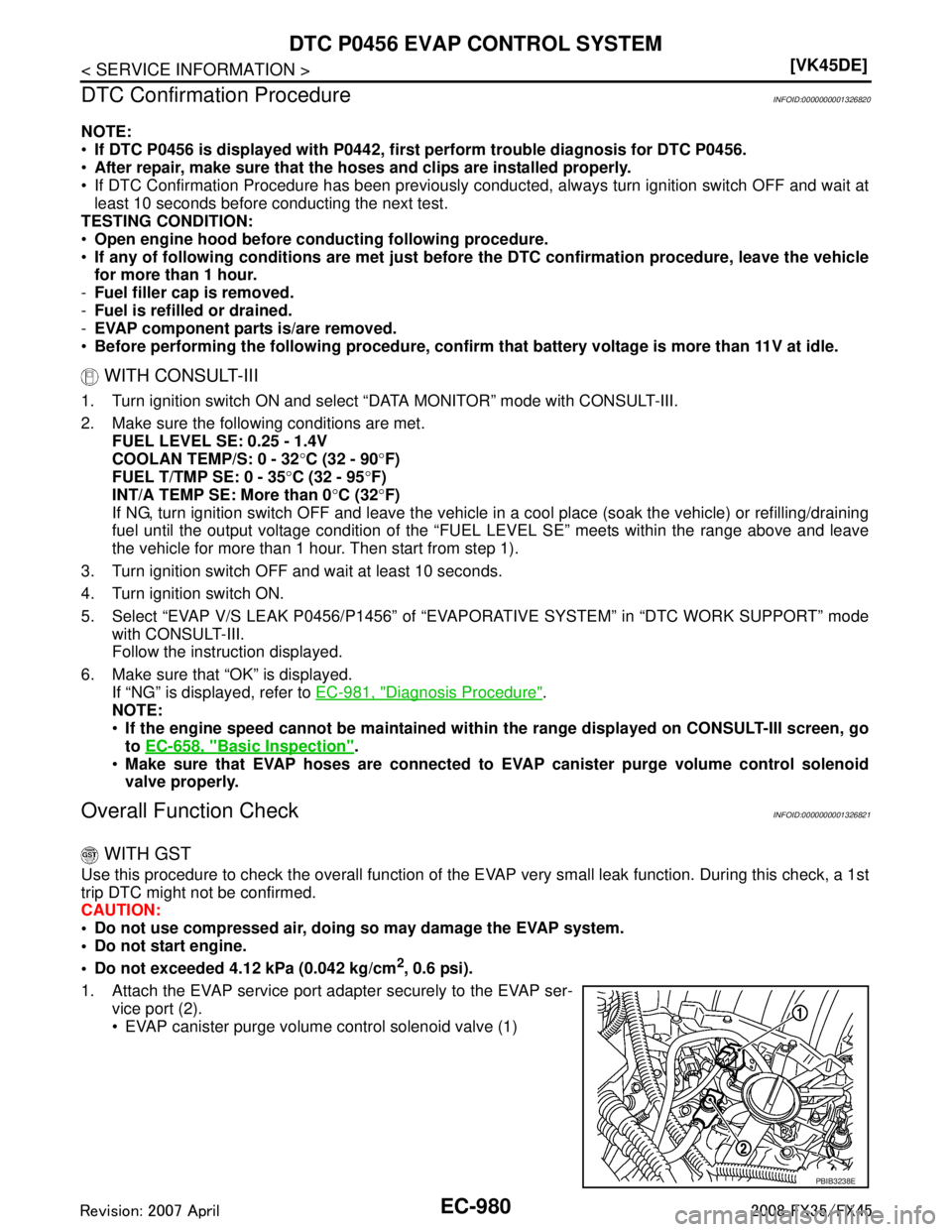
1. Attach the EVAP service port adapter securely to the EVAP ser- vice port (2).
EVAP canister purge volume control solenoid valve (1)
PBIB3238E
3AA93ABC3ACD3AC03ACA3AC03AC63AC53A913A773A893A873A873A8E3A773A983AC73AC93AC03AC3
3A893A873A873A8F3A773A9D3AAF3A8A3A8C3A863A9D3AAF3A8B3A8C
Page 2234 of 3924
EC-994
< SERVICE INFORMATION >[VK45DE]
DTC P0506 ISC SYSTEM
DTC P0506 ISC SYSTEM
DescriptionINFOID:0000000001326843
NOTE:
If DTC P0506 is displayed with ot
her DTC, first perform the trouble diagnosis for the other DTC.
The ECM controls the engine idle speed to a specified leve l through the fine adjustment of the air, which is let
into the intake manifold, by operating the electric thrott le control actuator. The operating of the throttle valve is
varied to allow for optimum control of the engine idli ng speed. The crankshaft position sensor (POS) detects
the actual engine speed and sends a signal to the ECM.
The ECM controls the electric throttle control actuator so that the engine speed coincides with the target value
memorized in the ECM. The target engine speed is t he lowest speed at which the engine can operate steadily.
The optimum value stored in the ECM is determined by taking into consideration various engine conditions,
such as during warming up, deceleration, and engine l oad (air conditioner, power steering and cooling fan
operation, etc.).
On Board Diagn osis LogicINFOID:0000000001326844
DTC Confirmation ProcedureINFOID:0000000001326845
NOTE:
If DTC Confirmation Procedure has been previously conduc ted, always turn ignition switch OFF and wait at
least 10 seconds before conducting the next test.
If the target idle speed is out of the specified value, perform EC-663, "
Idle Air Volume Learning",
before conducting DTC Confirmation Procedure. For the target idle speed, refer to the EC-1196
.
TESTING CONDITION:
Before performing the following procedure, confirm that battery voltage is more than 11V at idle.
Always perform the test at a temperature above −10 °C(14 °F).
WITH CONSULT-III
1. Open engine hood.
2. Start engine and warm it up to normal operating temperature.
3. Turn ignition switch OFF and wait at least 10 seconds.
4. Start engine and run it for at least 1 minute at idle speed.
5. Check 1st trip DTC.
6. If 1st trip DTC is detected, go to EC-994, "
Diagnosis Procedure".
Diagnosis ProcedureINFOID:0000000001326846
1.CHECK INTAKE AIR LEAK
1. Start engine and let it idle.
2. Listen for an intake air leak after the mass air flow sensor.
OK or NG
OK >> GO TO 2.
NG >> Discover air leak location and repair.
2.REPLACE ECM
1. Stop engine.
2. Replace ECM.
3. Perform initialization of IVIS (NATS) system and regist ration of all IVIS (NATS) ignition key IDs. Refer to
BL-187, "
ECM Re-Communicating Function".
4. Perform EC-662, "
VIN Registration".
5. Perform EC-662, "
Accelerator Pedal Released Position Learning".
DTC No. Trouble diagnosis name DTC detecting condition Possible cause
P0506
0506 Idle speed control sys-
tem RPM lower than ex-
pected The idle speed is less than the target idle speed
by 100 rpm or more.
Electric throttle control actuator
Intake air leak
3AA93ABC3ACD3AC03ACA3AC03AC63AC53A913A773A893A873A873A8E3A773A983AC73AC93AC03AC3
3A893A873A873A8F3A773A9D3AAF3A8A3A8C3A863A9D3AAF3A8B3A8C
Page 2236 of 3924
EC-996
< SERVICE INFORMATION >[VK45DE]
DTC P0507 ISC SYSTEM
DTC P0507 ISC SYSTEM
DescriptionINFOID:0000000001326847
NOTE:
If DTC P0507 is displayed with ot
her DTC, first perform the trouble diagnosis for the other DTC.
The ECM controls the engine idle speed to a specified leve l through the fine adjustment of the air, which is let
into the intake manifold, by operating the electric thrott le control actuator. The operating of the throttle valve is
varied to allow for optimum control of the engine idli ng speed. The crankshaft position sensor (POS) detects
the actual engine speed and sends a signal to the ECM.
The ECM controls the electric throttle control actuator so that the engine speed coincides with the target value
memorized in the ECM. The target engine speed is t he lowest speed at which the engine can operate steadily.
The optimum value stored in the ECM is determined by taking into consideration various engine conditions,
such as during warming up, deceleration, and engine l oad (air conditioner, power steering and cooling fan
operation, etc.).
On Board Diagn osis LogicINFOID:0000000001326848
DTC Confirmation ProcedureINFOID:0000000001326849
NOTE:
If DTC Confirmation Procedure has been previously conduc ted, always turn ignition switch OFF and wait at
least 10 seconds before conducting the next test.
If the target idle speed is out of the specified value, perform EC-663, "
Idle Air Volume Learning",
before conducting DTC Confirmation Procedure. For the target idle speed, refer to the EC-1196
.
TESTING CONDITION:
Before performing the following procedure, confirm that battery voltage is more than 11V at idle.
Always perform the test at a temperature above −10 °C(14 °F).
1. Open engine hood.
2. Start engine and warm it up to normal operating temperature.
3. Turn ignition switch OFF and wait at least 10 seconds.
4. Start engine and run it for at least 1 minute at idle speed.
5. Check 1st trip DTC.
6. If 1st trip DTC is detected, go to EC-996, "
Diagnosis Procedure".
Diagnosis ProcedureINFOID:0000000001326850
1.CHECK PCV HOSE CONNECTION
Confirm that PCV hose is connected correctly.
OK or NG
OK >> GO TO 2.
NG >> Repair or replace.
2.CHECK INTAKE AIR LEAK
1. Start engine and let it idle.
2. Listen for an intake air leak after the mass air flow sensor.
OK or NG
OK >> GO TO 3.
NG >> Discover air leak location and repair.
3.REPLACE ECM
1. Stop engine.
DTC No. Trouble diagnosis name DTC detecting condition Possible cause
P0507
0507 Idle speed control sys-
tem RPM higher than
expected The idle speed is more than the target idle
speed by 200 rpm or more. Electric throttle control actuator
Intake air leak
PCV system
3AA93ABC3ACD3AC03ACA3AC03AC63AC53A913A773A893A873A873A8E3A773A983AC73AC93AC03AC3
3A893A873A873A8F3A773A9D3AAF3A8A3A8C3A863A9D3AAF3A8B3A8C
Page 3068 of 3924
LAN-48
< SERVICE INFORMATION >[CAN]
TROUBLE DIAGNOSIS
NOTE:
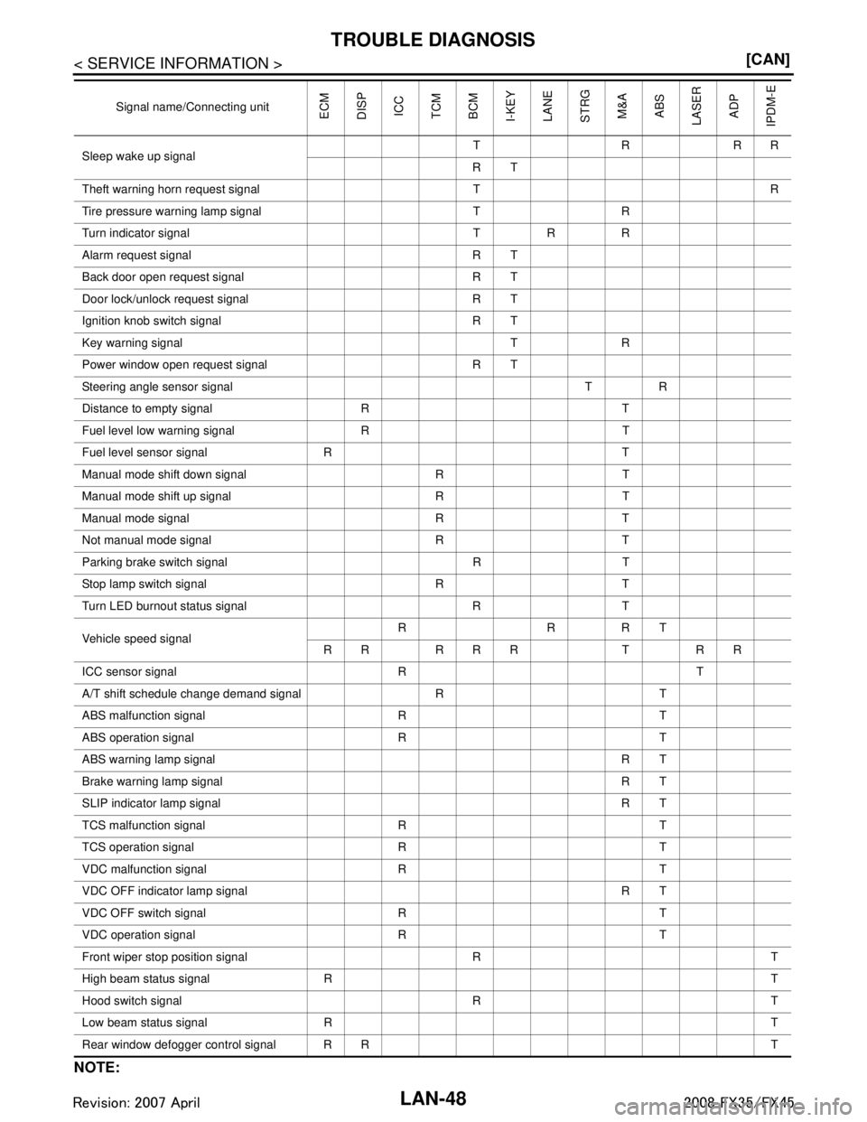
Sleep wake up signalTRRR
RT
Theft warning horn request signal T R
Tire pressure warn ing lamp signal T R
Turn indicator signal T R R
Alarm request signal R T
Back door open request signal R T
Door lock/unlock request signal R T
Ignition knob switch signal R T
Key warning signal T R
Power window open request signal R T
Steering angle sensor signal T R
Distance to empty signal R T
Fuel level low warning signal R T
Fuel level sensor signal R T
Manual mode shift down signal R T
Manual mode shift up signal R T
Manual mode signal R T
Not manual mode signal R T
Parking brake switch signal R T
Stop lamp switch signal R T
Turn LED burnout status signal R T
Vehicle speed signal RRRT
RR RRR T RR
ICC sensor signal R T
A/T shift schedule change demand signal R T
ABS malfunction signal R T
ABS operation signal R T
ABS warning lamp signal RT
Brake warning lamp signal RT
SLIP indicator lamp signal RT
TCS malfunction signal R T
TCS operation signal R T
VDC malfunction signal R T
VDC OFF indicator lamp signal R T
VDC OFF switch signal R T
VDC operation signal R T
Front wiper stop position signal R T
High beam status signal R T
Hood switch signal R T
Low beam status signal R T
Rear window defogger control signal R R T
Signal name/Connecting unit
ECM
DISP ICC
TCM
BCM
I-KEY
LANE
STRG M&AABS
LASER ADP
IPDM-E
3AA93ABC3ACD3AC03ACA3AC03AC63AC53A913A773A893A873A873A8E3A773A983AC73AC93AC03AC3
3A893A873A873A8F3A773A9D3AAF3A8A3A8C3A863A9D3AAF3A8B3A8C