2008 INFINITI FX35 ignition switch
[x] Cancel search: ignition switchPage 1139 of 3924
COMBINATION METERSDI-13
< SERVICE INFORMATION >
C
DE
F
G H
I
J
L
M A
B
DI
N
O P
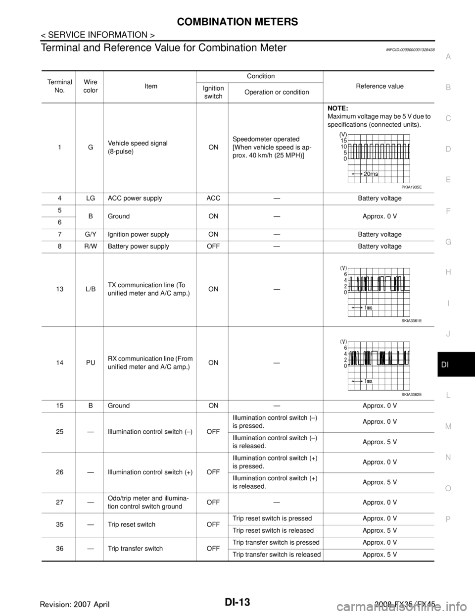
Terminal and Reference Va lue for Combination MeterINFOID:0000000001328438
Te r m i n a l
No. Wire
color Item Condition
Reference value
Ignition
switch Operation or condition
1G Vehicle speed signal
(8-pulse)
ONSpeedometer operated
[When vehicle speed is ap-
prox. 40 km/h (25 MPH)] NOTE:
Maximum voltage may be 5 V due to
specifications (connected units).
4 LG ACC power supply ACC — Battery voltage
5 B Ground ON — Approx. 0 V
6
7 G/Y Ignition power supply ON — Battery voltage
8 R/W Battery power supply OFF — Battery voltage
13 L/B TX communication line (To
unified meter and A/C amp.)
ON —
14 PU RX communication line (From
unified meter and A/C amp.) ON —
15 B Ground ON — Approx. 0 V
25 — Illumination control switch (–) OFF Illumination control switch (–)
is pressed.
Approx. 0 V
Illumination control switch (–)
is released. Approx. 5 V
26 — Illumination control switch (+) OFF Illumination control switch (+)
is pressed.
Approx. 0 V
Illumination control switch (+)
is released. Approx. 5 V
27 — Odo/trip meter and illumina-
tion control switch ground
OFF — Approx. 0 V
35 — Trip reset switch OFF Trip reset switch is pressed Approx. 0 V
Trip reset switch is released Approx. 5 V
36 — Trip transfer switch OFF Trip transfer switch is pressed Approx. 0 V
Trip transfer switch is released Approx. 5 V
PKIA1935E
SKIA3361E
SKIA3362E
3AA93ABC3ACD3AC03ACA3AC03AC63AC53A913A773A893A873A873A8E3A773A983AC73AC93AC03AC3
3A893A873A873A8F3A773A9D3AAF3A8A3A8C3A863A9D3AAF3A8B3A8C
Page 1140 of 3924
DI-14
< SERVICE INFORMATION >
COMBINATION METERS
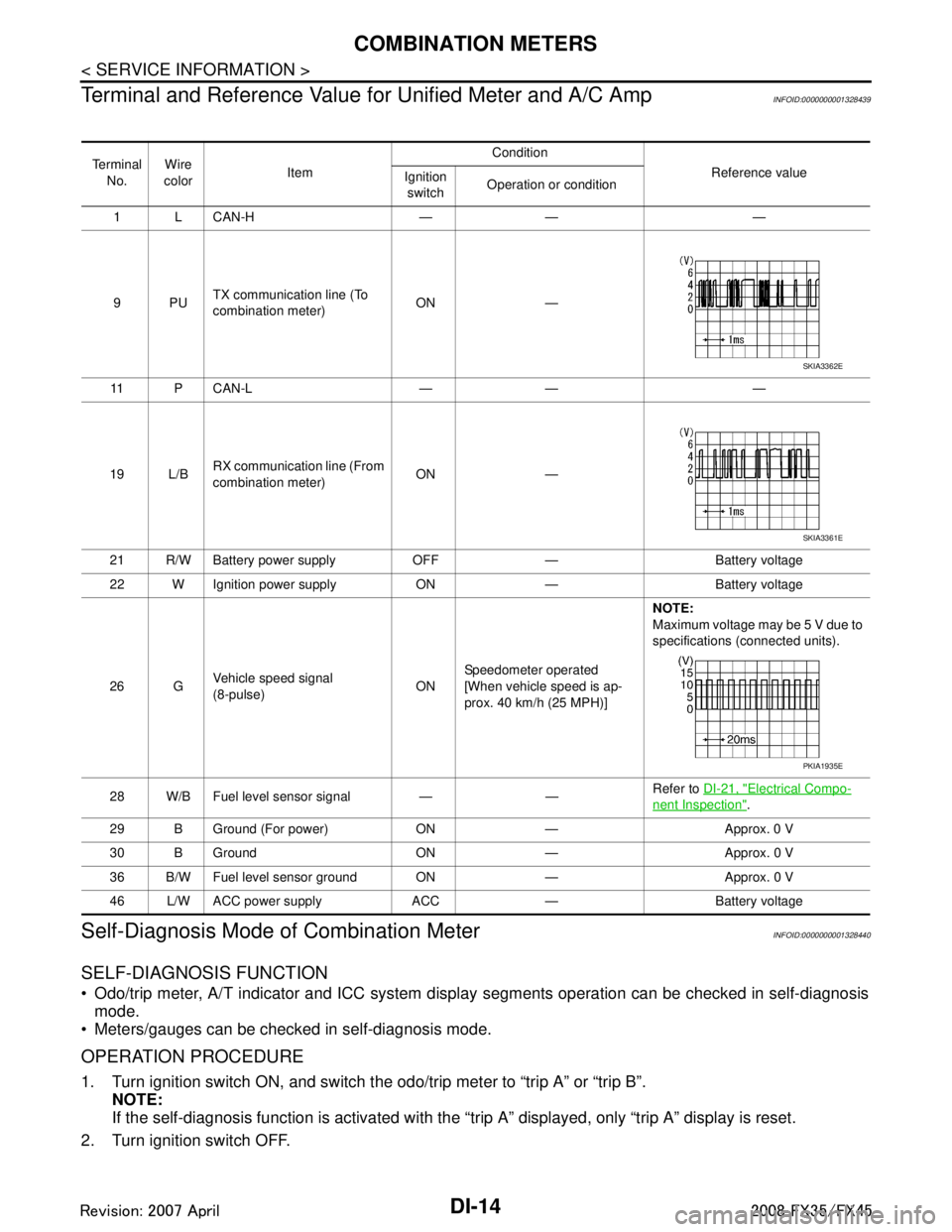
Terminal and Reference Value for Unified Meter and A/C Amp
INFOID:0000000001328439
Self-Diagnosis Mode of Combination MeterINFOID:0000000001328440
SELF-DIAGNOSIS FUNCTION
Odo/trip meter, A/T indicator and ICC system disp lay segments operation can be checked in self-diagnosis
mode.
Meters/gauges can be checked in self-diagnosis mode.
OPERATION PROCEDURE
1. Turn ignition switch ON, and switch the odo/trip meter to “trip A” or “trip B”. NOTE:
If the self-diagnosis function is activated with the “t rip A” displayed, only “trip A” display is reset.
2. Turn ignition switch OFF.
Te r m i n a l No. Wire
color Item Condition
Reference value
Ignition
switch Operation or condition
1 L CAN-H — — —
9PU TX communication line (To
combination meter) ON —
11 P C A N - L — — —
19 L/B RX communication line (From
combination meter) ON —
21 R/W Battery power supply OFF — Battery voltage
22 W Ignition power supply ON — Battery voltage
26 G Vehicle speed signal
(8-pulse)
ONSpeedometer operated
[When vehicle speed is ap-
prox. 40 km/h (25 MPH)] NOTE:
Maximum voltage may be 5 V due to
specifications (connected units).
28 W/B Fuel level sensor signal — — Refer to
DI-21, "
Electrical Compo-
nent Inspection".
29 B Ground (For power) ON — Approx. 0 V
30 B Ground ON — Approx. 0 V
36 B/W Fuel level sensor ground ON — Approx. 0 V
46 L/W ACC power supply ACC — Battery voltage
SKIA3362E
SKIA3361E
PKIA1935E
3AA93ABC3ACD3AC03ACA3AC03AC63AC53A913A773A893A873A873A8E3A773A983AC73AC93AC03AC3
3A893A873A873A8F3A773A9D3AAF3A8A3A8C3A863A9D3AAF3A8B3A8C
Page 1141 of 3924

COMBINATION METERSDI-15
< SERVICE INFORMATION >
C
DE
F
G H
I
J
L
M A
B
DI
N
O P
3. Turn ignition switch ON while pressing trip transfer switch and trip reset switch at the same time.
4. After ignition switch is turned ON, release trip transfer switch and trip reset switch (within 7 seconds after the ignition switch is
turned ON).
5. All the segments on the odo/trip meter, A/T indi cator and ICC system display illuminates, and simulta-
neously the low-fuel warning lamp indicator illuminates. At this time, the unified meter control unit is turned
to self-diagnosis mode.
NOTE:
Check odo/trip meter switch and combination meter power supply and ground circuit when self-diagno-
sis mode of combination meter does not start. Replace combination meter if the results of the check are
normal.
If any of the segments are not disp layed, replace combination meter.
6. Each meter/gauge activates during pressing trip reset switch. (Then low-fuel warning lamp turns OFF.)
NOTE:
If any of the meters/gauges are not activated, replace thecombination meter.
The figure is reference.
CONSULT-III Function (METER/M&A)INFOID:0000000001328441
Refer to DI-27, "CONSULT-III Function (METER/M&A)" in “UNIFIED METER AND A/C AMP”.
Trouble DiagnosisINFOID:0000000001328442
HOW TO PERFORM TROUBLE DIAGNOSIS
1. Confirm the symptom or customer complaint.
2. Perform preliminary check. Refer to "PRELIMINARY CHECK".
3. According to the symptom chart, repair or replace the cause of the symptom. Refer to DI-16, "
Symptom
Chart".
4. Does the meter operate normally? If so, GO TO 5. If not, GO TO 2.
5. INSPECTION END
PRELIMINARY CHECK
1.CHECK OPERATION OF SELF-DIAGNOSIS MODE (COMBINATION METER)
SKIA4817E
SKIA6170E
SKIA4831E
3AA93ABC3ACD3AC03ACA3AC03AC63AC53A913A773A893A873A873A8E3A773A983AC73AC93AC03AC3
3A893A873A873A8F3A773A9D3AAF3A8A3A8C3A863A9D3AAF3A8B3A8C
Page 1142 of 3924
DI-16
< SERVICE INFORMATION >
COMBINATION METERS
Perform self-diagnosis mode of combination meter. Refer to DI-14, "Self-Diagnosis Mode of Combination
Meter".
Does self-diagnosis function operate?
YES >> GO TO 2.
NO >> GO TO 3.
2.CHECK UNIFIED METER AND A/C AMP. (CONSULT-III)
Perform self-diagnosis of unified meter and A/C amp. Refer to DI-27, "
CONSULT-III Function (METER/M&A)".
Self-diagnosis results
No malfunction detected >> INSPECTION END
Malfunction detected >> Check applicable parts, and repair or replace corresponding parts.
3.CHECK POWER SUPPLY AND GROUND CIRCUIT OF COMBINATION METER
Check power supply and ground circuit of combination meter. Refer to DI-16, "
Power Supply and Ground Cir-
cuit Inspection".
OK or NG
OK >> Check odo/trip meter switch. Refer to DI-21, "Odo/Trip Meter and Illumination Control Switch
Inspection".
NG >> Repair malfunctioning part.
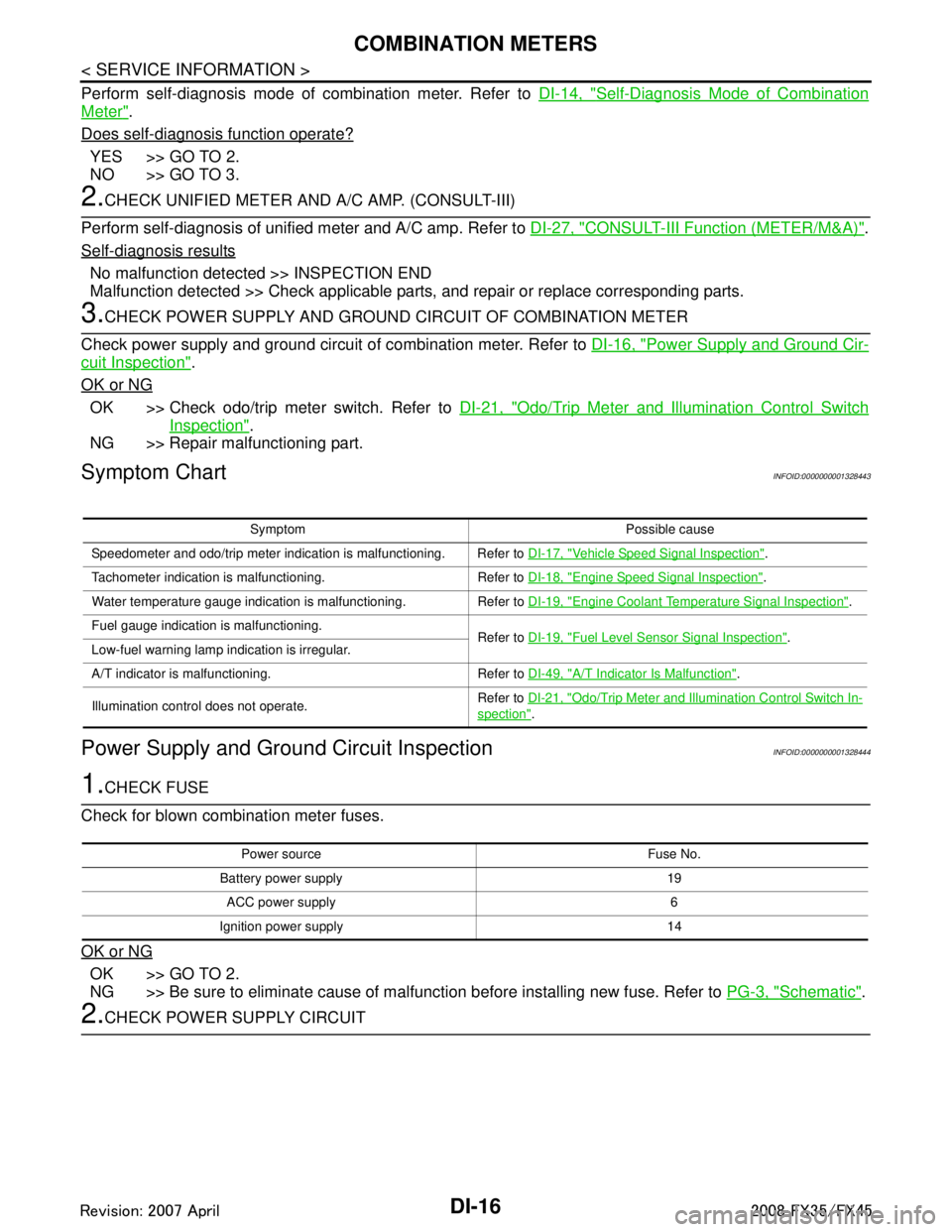
Symptom ChartINFOID:0000000001328443
Power Supply and Ground Circuit InspectionINFOID:0000000001328444
1.CHECK FUSE
Check for blown combination meter fuses.
OK or NG
OK >> GO TO 2.
NG >> Be sure to eliminate cause of malfunction before installing new fuse. Refer to PG-3, "
Schematic".
2.CHECK POWER SUPPLY CIRCUIT
Symptom Possible cause
Speedometer and odo/trip meter indication is malfunctioning. Refer to DI-17, "
Vehicle Speed Signal Inspection".
Tachometer indication is malfunctioning. Refer to DI-18, "
Engine Speed Signal Inspection".
Water temperature gauge indication is malfunctioning. Refer to DI-19, "
Engine Coolant Temperature Signal Inspection".
Fuel gauge indication is malfunctioning. Refer to DI-19, "
Fuel Level Sensor Signal Inspection".
Low-fuel warning lamp indication is irregular.
A/T indicator is malfunctioning. Refer to DI-49, "
A/T Indicator Is Malfunction".
Illumination control does not operate. Refer to
DI-21, "
Odo/Trip Meter and Illumination Control Switch In-
spection".
Power source Fuse No.
Battery power supply 19 ACC power supply 6
Ignition power supply 14
3AA93ABC3ACD3AC03ACA3AC03AC63AC53A913A773A893A873A873A8E3A773A983AC73AC93AC03AC3
3A893A873A873A8F3A773A9D3AAF3A8A3A8C3A863A9D3AAF3A8B3A8C
Page 1143 of 3924
COMBINATION METERSDI-17
< SERVICE INFORMATION >
C
DE
F
G H
I
J
L
M A
B
DI
N
O P
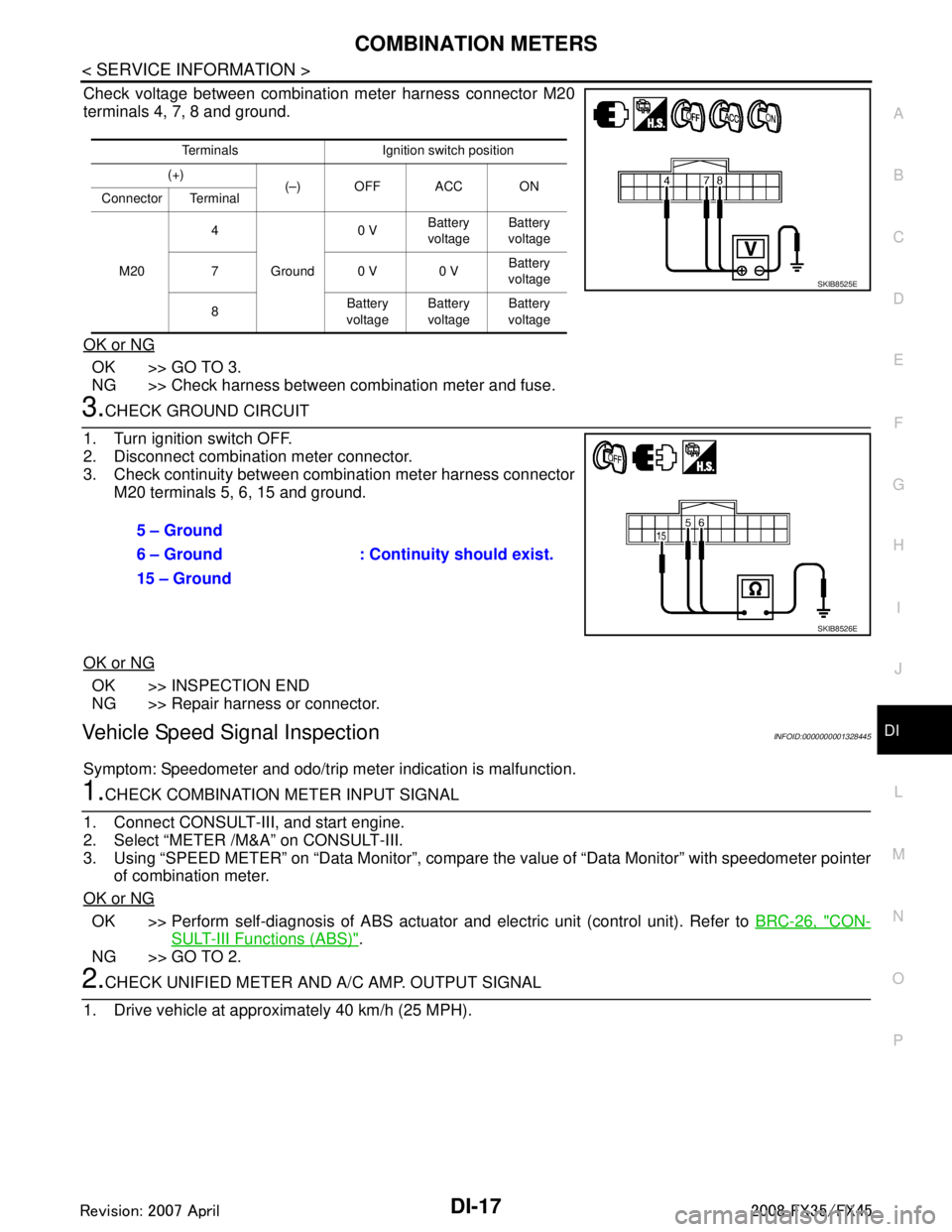
Check voltage between combination meter harness connector M20
terminals 4, 7, 8 and ground.
OK or NG
OK >> GO TO 3.
NG >> Check harness between combination meter and fuse.
3.CHECK GROUND CIRCUIT
1. Turn ignition switch OFF.
2. Disconnect combination meter connector.
3. Check continuity between combination meter harness connector M20 terminals 5, 6, 15 and ground.
OK or NG
OK >> INSPECTION END
NG >> Repair harness or connector.
Vehicle Speed Signal InspectionINFOID:0000000001328445
Symptom: Speedometer and odo/trip meter indication is malfunction.
1.CHECK COMBINATION METER INPUT SIGNAL
1. Connect CONSULT-III, and start engine.
2. Select “METER /M&A” on CONSULT-III.
3. Using “SPEED METER” on “Data Moni tor”, compare the value of “Data Monitor” with speedometer pointer
of combination meter.
OK or NG
OK >> Perform self-diagnosis of ABS actuator and electric unit (control unit). Refer to BRC-26, "CON-
SULT-III Functions (ABS)".
NG >> GO TO 2.
2.CHECK UNIFIED METER AND A/ C AMP. OUTPUT SIGNAL
1. Drive vehicle at approximately 40 km/h (25 MPH).
Terminals Ignition switch position
(+) (–) OFF ACC ON
Connector Terminal
M20 4
Ground 0 V
Battery
voltage Battery
voltage
70 V0 V Battery
voltage
8 Battery
voltage Battery
voltage Battery
voltage
SKIB8525E
5 – Ground
: Continuity should exist.
6 – Ground
15 – Ground
SKIB8526E
3AA93ABC3ACD3AC03ACA3AC03AC63AC53A913A773A893A873A873A8E3A773A983AC73AC93AC03AC3
3A893A873A873A8F3A773A9D3AAF3A8A3A8C3A863A9D3AAF3A8B3A8C
Page 1144 of 3924

DI-18
< SERVICE INFORMATION >
COMBINATION METERS
2. Check voltage signal between unified meter and A/C amp. har-ness connector M56 terminal 26 and ground.
OK or NG
OK >> GO TO 3.
NG-1 >> If monitor indicates “0 V” constantly, perform the following. 1. Check each unit inputting vehicle speed signal (8 pulse), harness and connector betweeneach unit and unified meter and A/C amp.
2. Repair or replace malfunctioning part.
NG-2 >> If monitor indicates “5 V” or “12 V” constantly, replace unified meter and A/C amp. Refer to DI-32,
"Removal and Installation of Unified Meter and A/C Amp".
3.CHECK CONTINUITY BETWEEN COMBINATION METER AND UNIFIED METER AND A/C AMP.
1. Turn ignition switch OFF.
2. Disconnect combination meter connector and unified meter and A/C amp. connector.
3. Check continuity between combination meter harness connector
M20 terminal 1 and unified meter and A/C amp. harness con-
nector M56 terminal 26.
OK or NG
OK >> Replace combination meter.
NG >> Repair harness or connector.
Engine Speed Signal InspectionINFOID:0000000001328446
Symptom: Tachometer indication is malfunction.
1.CHECK COMBINATION METER INPUT SIGNAL
1. Connect CONSULT-III, and start engine.
2. Select “METER/M&A” on CONSULT-III.
3. Using “TACHO METER” on “Data Monitor”, compare the value of “Data Monitor” with tachometer pointer
of combination meter.
OK or NG
OK >> GO TO 2.
NG >> Replace combination meter.
2.CHECK UNIFIED METER AND A/C AMP. INPUT SIGNAL
Select “Data Monitor” of CONSULT-III to compare values between “ ENG SPEED” of “ENGINE” and “TACHO
METER” of “METER/M&A”.
OK or NG
OK >> Perform self-diagnosis of ECM. Refer to EC-117, "CONSULT-III Function (ENGINE)" (VQ35DE)
or EC-695, "
CONSULT-III Function (ENGINE)" (VK45DE).
NG >> Replace unified meter and A/C amp. Refer to DI-32, "
Removal and Installation of Unified Meter
and A/C Amp".
26 – Ground:
NOTE:
Maximum voltage may be 5 V due to
specifications (connected units).
SKIB0338E
PKIA1935E
1 – 26 : Continuity should exist.
SKIB0343E
3AA93ABC3ACD3AC03ACA3AC03AC63AC53A913A773A893A873A873A8E3A773A983AC73AC93AC03AC3
3A893A873A873A8F3A773A9D3AAF3A8A3A8C3A863A9D3AAF3A8B3A8C
Page 1145 of 3924
COMBINATION METERSDI-19
< SERVICE INFORMATION >
C
DE
F
G H
I
J
L
M A
B
DI
N
O P
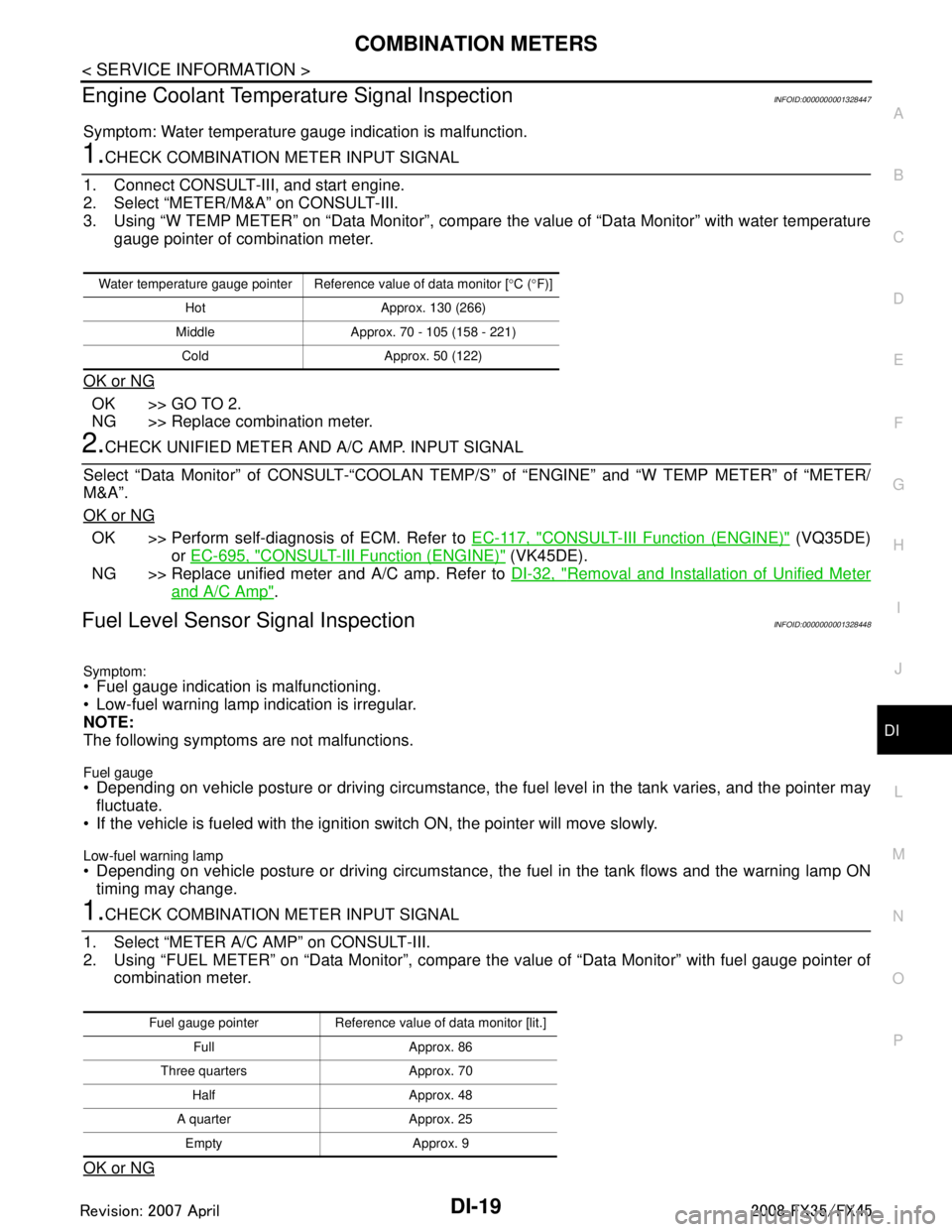
Engine Coolant Temperature Signal InspectionINFOID:0000000001328447
Symptom: Water temperature gauge indication is malfunction.
1.CHECK COMBINATION METER INPUT SIGNAL
1. Connect CONSULT-III, and start engine.
2. Select “METER/M&A” on CONSULT-III.
3. Using “W TEMP METER” on “Data Monitor”, compare the value of “Data Monitor” with water temperature
gauge pointer of combination meter.
OK or NG
OK >> GO TO 2.
NG >> Replace combination meter.
2.CHECK UNIFIED METER AND A/C AMP. INPUT SIGNAL
Select “Data Monitor” of CONSULT-“COOLAN TEMP/S ” of “ENGINE” and “W TEMP METER” of “METER/
M&A”.
OK or NG
OK >> Perform self-diagnosis of ECM. Refer to EC-117, "CONSULT-III Function (ENGINE)" (VQ35DE)
or EC-695, "
CONSULT-III Function (ENGINE)" (VK45DE).
NG >> Replace unified meter and A/C amp. Refer to DI-32, "
Removal and Installation of Unified Meter
and A/C Amp".
Fuel Level Sensor Signal InspectionINFOID:0000000001328448
Symptom:
Fuel gauge indication is malfunctioning.
Low-fuel warning lamp indication is irregular.
NOTE:
The following symptoms are not malfunctions.
Fuel gauge Depending on vehicle posture or driving circumstance, the fuel level in the tank varies, and the pointer may
fluctuate.
If the vehicle is fueled with the ignition switch ON, the pointer will move slowly.
Low-fuel warning lamp
Depending on vehicle posture or driving circumstance, t he fuel in the tank flows and the warning lamp ON
timing may change.
1.CHECK COMBINATION METER INPUT SIGNAL
1. Select “METER A/C AMP” on CONSULT-III.
2. Using “FUEL METER” on “Data Monitor”, compare t he value of “Data Monitor” with fuel gauge pointer of
combination meter.
OK or NG
Water temperature gauge pointer Reference value of data monitor [ °C ( °F)]
Hot Approx. 130 (266)
Middle Approx. 70 - 105 (158 - 221) Cold Approx. 50 (122)
Fuel gauge pointer Reference value of data monitor [lit.] Full Approx. 86
Three quarters Approx. 70 Half Approx. 48
A quarter Approx. 25 Empty Approx. 9
3AA93ABC3ACD3AC03ACA3AC03AC63AC53A913A773A893A873A873A8E3A773A983AC73AC93AC03AC3
3A893A873A873A8F3A773A9D3AAF3A8A3A8C3A863A9D3AAF3A8B3A8C
Page 1146 of 3924

DI-20
< SERVICE INFORMATION >
COMBINATION METERS
OK >> GO TO 2.
NG >> Replace combination meter.
2.CHECK FUEL LEVEL SENSOR (SUB) CIRCUIT
1. Turn ignition switch OFF.
2. Disconnect unified meter and A/C amp. connector and fuel level sensor unit (sub) connector.
3. Check continuity between unified meter and A/C amp. harness
connector (A) M56 terminal 28 and fuel level sensor unit (sub)
harness connector (B) B40 terminal 1.
4. Check continuity between unified meter and A/C amp. harness connector (A) M56 terminal 28 and ground.
OK or NG
OK >> GO TO 3.
NG >> Repair harness or connector.
3.CHECK FUEL LEVEL SENSOR (MAIN·SUB) CIRCUIT
1. Disconnect fuel level sensor unit and fuel pump (main) connector.
2. Check continuity between fuel level sensor unit (sub) harness
connector (A) B40 terminal 2 and fuel level sensor unit and fuel
pump (main) harness connector (B) B39 terminal 2.
3. Check continuity between fuel level sensor unit (sub) harness
connector (A) B40 terminal 2 and ground.
OK or NG
OK >> GO TO 4.
NG >> Repair harness or connector.
4.CHECK FUEL LEVEL SENSOR (MAIN) CIRCUIT
1. Check continuity between fuel level sensor unit and fuel pump (main) harness connector (A) B39 terminal 5 and unified meter
and A/C amp. harness connector (B) M56 terminal 36.
2. Check continuity between fuel level sensor unit and fuel pump (main) harness connector (A) B39 terminal 5 and ground.
OK or NG
OK >> GO TO 5.
NG >> Repair harness or connector.
5.CHECK FUEL LEVEL SENSOR
Check components. Refer to DI-21, "
Electrical Component Inspection".
OK or NG
OK >> Check fuel level sensor unit installation, and c heck whether the float arm interferes or binds with
any of the internal components in the fuel tank. Repair or replace malfunctioning part, if neces-
sary.
NG >> Replace fuel level sensor unit. 28 – 1 : Continuity should exist.
28 – Ground : Continuity should not exist.
SKIB8527E
2 – 2 : Continuity should exist.
2 – Ground : Continuity should not exist.
SKIB8697E
5 – 36 : Continuity should exist.
5 – Ground : Continuity should not exist.
SKIB8528E
3AA93ABC3ACD3AC03ACA3AC03AC63AC53A913A773A893A873A873A8E3A773A983AC73AC93AC03AC3
3A893A873A873A8F3A773A9D3AAF3A8A3A8C3A863A9D3AAF3A8B3A8C