2008 INFINITI FX35 ignition switch
[x] Cancel search: ignition switchPage 1189 of 3924

WARNING CHIMEDI-63
< SERVICE INFORMATION >
C
DE
F
G H
I
J
L
M A
B
DI
N
O P
OK or NG
OK >> GO TO 3.
NG >> Replace BCM. Refer to BCS-13, "
Removal and Installation of BCM".
3.CHECK BATTERY POWER SUPPLY CIRCUIT OF COMBINATION METER
Check battery power supply circuit of combination meter. Refer to DI-16, "
Power Supply and Ground Circuit
Inspection".
OK or NG
OK >> Replace combination meter.
NG >> Check harness between combination meter and fuse.
4.CHECK BATTERY POWER SUPPLY CIRCUI T OF UNIFIED METER AND A/C AMP.
Check battery power supply circuit of unified meter and A/C amp. Refer to DI-29, "
Power Supply and Ground
Circuit Inspection".
OK or NG
OK >> INSPECTION END
NG >> Check harness between unified meter and A/C amp. and fuse.
Front Door Switch (Drive r Side) Signal InspectionINFOID:0000000001328486
1.CHECK BCM INPUT SIGNAL
With CONSULT-III
1. Select “BCM” on consult-III.
2. With “Data Monitor” of “BUZZER”, confirm “D OOR SW-DR” when the driver side door is operated.
Without CONSULT-III
Check voltage between BCM harness connector B14 terminal 62 and ground.
OK or NG
OK >> INSPECTION END
NG >> GO TO 2.
2.CHECK FRONT DOOR SWIT CH (DRIVER SIDE) CIRCUIT
1. Turn ignition switch OFF.
2. Disconnect BCM connector and front door switch (driver side) connector. When meeting the requirements
to sound warning chime
: On
Except above : Off
“DOOR SW-DR”
When driver side door is opened : On
When driver side door is closed : Off
62 – Ground
When driver side door is opened : Approx. 0 V
When driver side door is closed : Approx. 12 V
3AA93ABC3ACD3AC03ACA3AC03AC63AC53A913A773A893A873A873A8E3A773A983AC73AC93AC03AC3
3A893A873A873A8F3A773A9D3AAF3A8A3A8C3A863A9D3AAF3A8B3A8C
Page 1190 of 3924
DI-64
< SERVICE INFORMATION >
WARNING CHIME
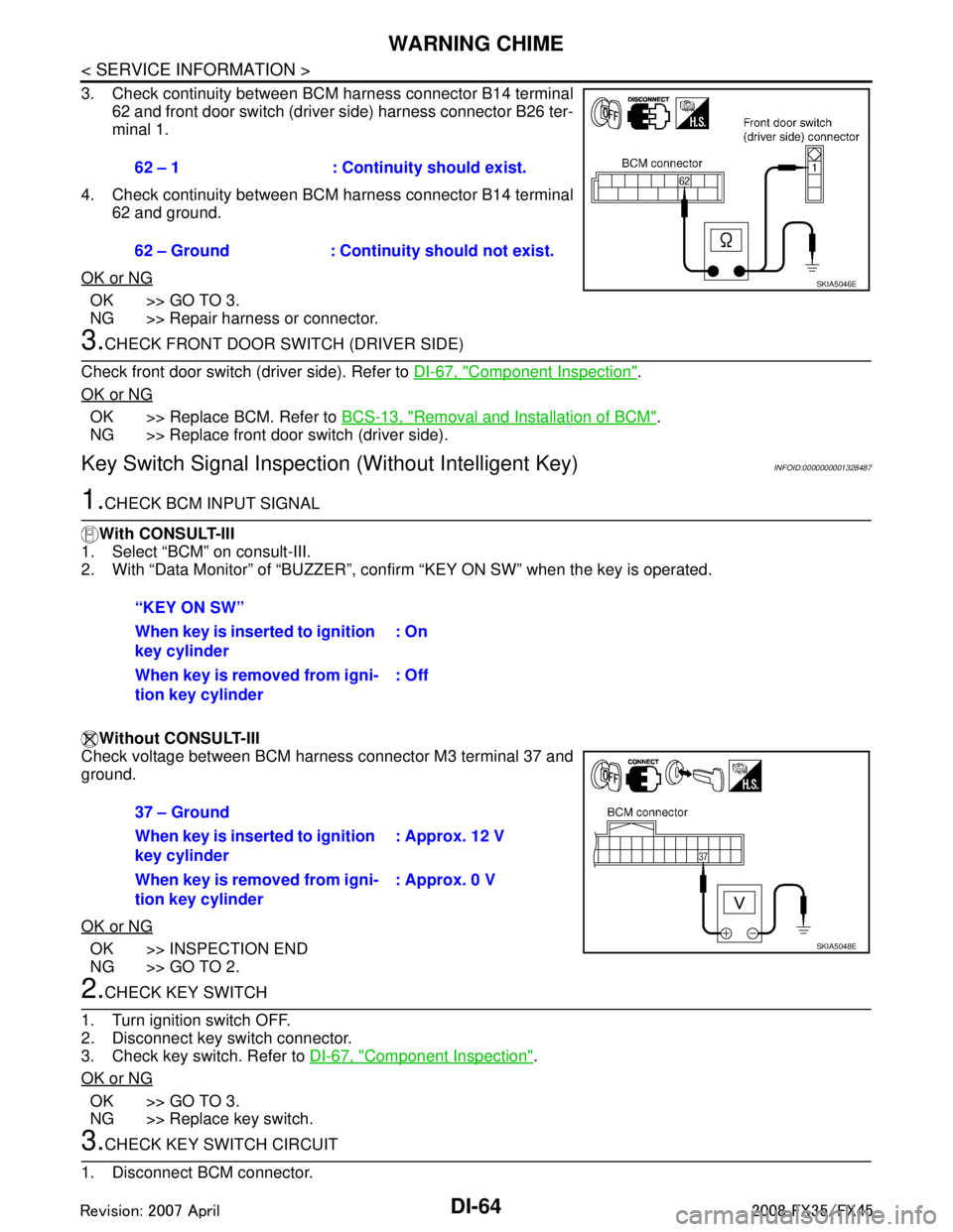
3. Check continuity between BCM harness connector B14 terminal62 and front door switch (driver side) harness connector B26 ter-
minal 1.
4. Check continuity between BCM harness connector B14 terminal 62 and ground.
OK or NG
OK >> GO TO 3.
NG >> Repair harness or connector.
3.CHECK FRONT DOOR SWITCH (DRIVER SIDE)
Check front door switch (driver side). Refer to DI-67, "
Component Inspection".
OK or NG
OK >> Replace BCM. Refer to BCS-13, "Removal and Installation of BCM".
NG >> Replace front door switch (driver side).
Key Switch Signal Inspection (Without Intelligent Key)INFOID:0000000001328487
1.CHECK BCM INPUT SIGNAL
With CONSULT-III
1. Select “BCM” on consult-III.
2. With “Data Monitor” of “BUZZER”, conf irm “KEY ON SW” when the key is operated.
Without CONSULT-III
Check voltage between BCM harness connector M3 terminal 37 and
ground.
OK or NG
OK >> INSPECTION END
NG >> GO TO 2.
2.CHECK KEY SWITCH
1. Turn ignition switch OFF.
2. Disconnect key switch connector.
3. Check key switch. Refer to DI-67, "
Component Inspection".
OK or NG
OK >> GO TO 3.
NG >> Replace key switch.
3.CHECK KEY SWITCH CIRCUIT
1. Disconnect BCM connector. 62 – 1 : Continui
ty should exist.
62 – Ground : Continuity should not exist.
SKIA5046E
“KEY ON SW”
When key is inserte d to ignition
key cylinder : On
When key is removed from igni-
tion key cylinder : Off
37 – Ground
When key is inserte
d to ignition
key cylinder : Approx. 12 V
When key is removed from igni-
tion key cylinder : Approx. 0 V
SKIA5048E
3AA93ABC3ACD3AC03ACA3AC03AC63AC53A913A773A893A873A873A8E3A773A983AC73AC93AC03AC3
3A893A873A873A8F3A773A9D3AAF3A8A3A8C3A863A9D3AAF3A8B3A8C
Page 1191 of 3924
WARNING CHIMEDI-65
< SERVICE INFORMATION >
C
DE
F
G H
I
J
L
M A
B
DI
N
O P
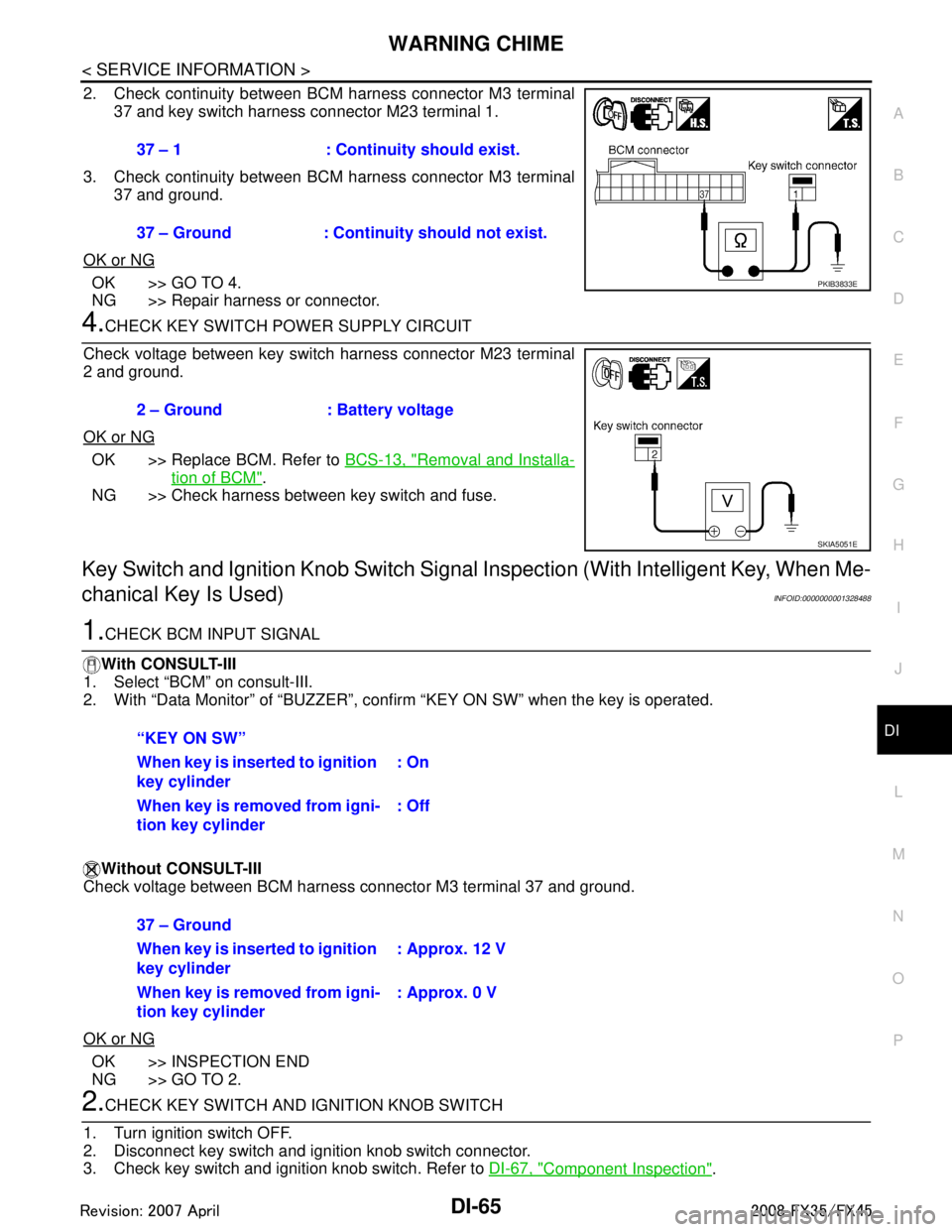
2. Check continuity between BCM harness connector M3 terminal 37 and key switch harness connector M23 terminal 1.
3. Check continuity between BCM harness connector M3 terminal 37 and ground.
OK or NG
OK >> GO TO 4.
NG >> Repair harness or connector.
4.CHECK KEY SWITCH POWER SUPPLY CIRCUIT
Check voltage between key switch harness connector M23 terminal
2 and ground.
OK or NG
OK >> Replace BCM. Refer to BCS-13, "Removal and Installa-
tion of BCM".
NG >> Check harness between key switch and fuse.
Key Switch and Ignition Knob Switch Signal Inspection (With Intelligent Key, When Me-
chanical Key Is Used)
INFOID:0000000001328488
1.CHECK BCM INPUT SIGNAL
With CONSULT-III
1. Select “BCM” on consult-III.
2. With “Data Monitor” of “BUZZER”, conf irm “KEY ON SW” when the key is operated.
Without CONSULT-III
Check voltage between BCM harness connector M3 terminal 37 and ground.
OK or NG
OK >> INSPECTION END
NG >> GO TO 2.
2.CHECK KEY SWITCH AND IG NITION KNOB SWITCH
1. Turn ignition switch OFF.
2. Disconnect key switch and i gnition knob switch connector.
3. Check key switch and ignition knob switch. Refer to DI-67, "
Component Inspection".
37 – 1 : Continuity should exist.
37 – Ground : Continuity should not exist.
PKIB3833E
2 – Ground : Battery voltage
SKIA5051E
“KEY ON SW”
When key is inserted to ignition
key cylinder
: On
When key is removed from igni-
tion key cylinder : Off
37 – Ground
When key is inserted to ignition
key cylinder: Approx. 12 V
When key is removed from igni-
tion key cylinder : Approx. 0 V
3AA93ABC3ACD3AC03ACA3AC03AC63AC53A913A773A893A873A873A8E3A773A983AC73AC93AC03AC3
3A893A873A873A8F3A773A9D3AAF3A8A3A8C3A863A9D3AAF3A8B3A8C
Page 1192 of 3924
DI-66
< SERVICE INFORMATION >
WARNING CHIME
OK or NG
OK >> GO TO 3.
NG >> Replace key switch and ignition knob switch.
3.CHECK KEY SWITCH AND IGNITION KNOB SWITCH CIRCUIT
1. Disconnect BCM connector.
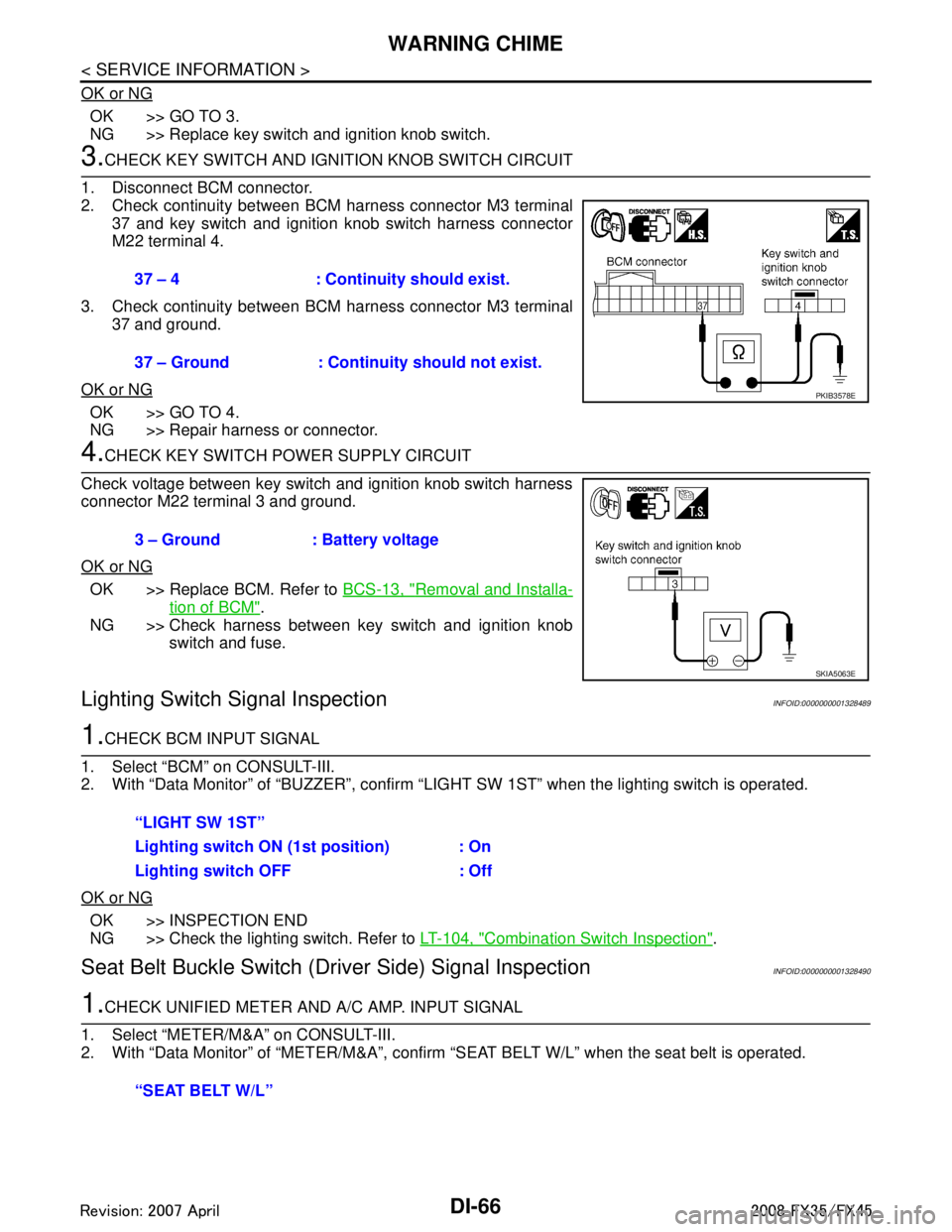
2. Check continuity between BCM harness connector M3 terminal 37 and key switch and ignition knob switch harness connector
M22 terminal 4.
3. Check continuity between BCM harness connector M3 terminal 37 and ground.
OK or NG
OK >> GO TO 4.
NG >> Repair harness or connector.
4.CHECK KEY SWITCH PO WER SUPPLY CIRCUIT
Check voltage between key switch and ignition knob switch harness
connector M22 terminal 3 and ground.
OK or NG
OK >> Replace BCM. Refer to BCS-13, "Removal and Installa-
tion of BCM".
NG >> Check harness between key switch and ignition knob switch and fuse.
Lighting Switch Signal InspectionINFOID:0000000001328489
1.CHECK BCM INPUT SIGNAL
1. Select “BCM” on CONSULT-III.
2. With “Data Monitor” of “BUZZER”, confirm “LIG HT SW 1ST” when the lighting switch is operated.
OK or NG
OK >> INSPECTION END
NG >> Check the lighting switch. Refer to LT-104, "
Combination Switch Inspection".
Seat Belt Buckle Switch (Driver Side) Signal InspectionINFOID:0000000001328490
1.CHECK UNIFIED METER AND A/C AMP. INPUT SIGNAL
1. Select “METER/M&A” on CONSULT-III.
2. With “Data Monitor” of “MET ER/M&A”, confirm “SEAT BELT W/L” when the seat belt is operated.
37 – 4 : Continuity should exist.
37 – Ground : Continuity should not exist.
PKIB3578E
3 – Ground : Battery voltage
SKIA5063E
“LIGHT SW 1ST”
Lighting switch ON (1st position) : On
Lighting switch OFF : Off
“SEAT BELT W/L”
3AA93ABC3ACD3AC03ACA3AC03AC63AC53A913A773A893A873A873A8E3A773A983AC73AC93AC03AC3
3A893A873A873A8F3A773A9D3AAF3A8A3A8C3A863A9D3AAF3A8B3A8C
Page 1193 of 3924
WARNING CHIMEDI-67
< SERVICE INFORMATION >
C
DE
F
G H
I
J
L
M A
B
DI
N
O P
OK or NG
OK >> INSPECTION END
NG >> GO TO 2.
2.CHECK COMBINATION METER INPUT SIGNAL
1. Turn ignition switch ON.
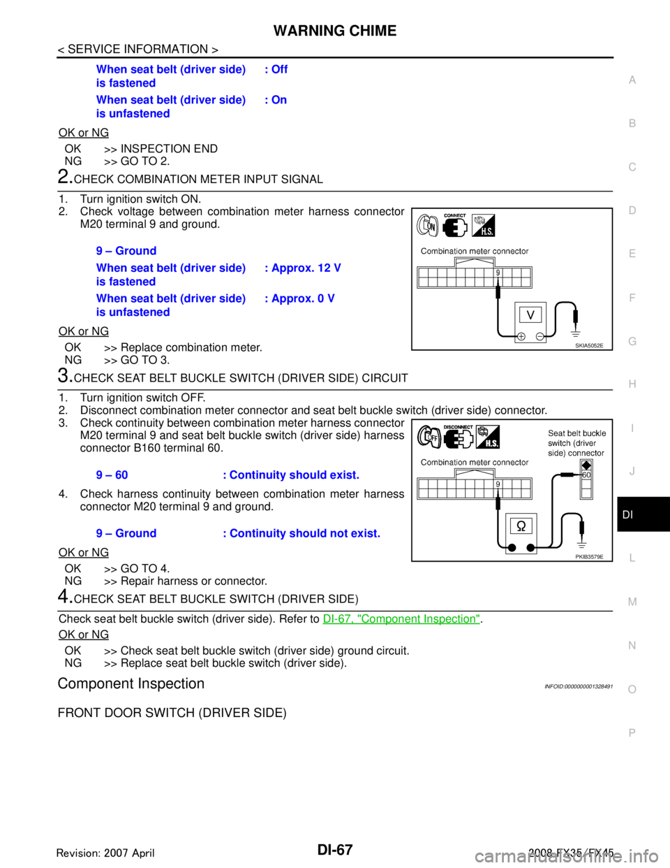
2. Check voltage between combination meter harness connector M20 terminal 9 and ground.
OK or NG
OK >> Replace combination meter.
NG >> GO TO 3.
3.CHECK SEAT BELT BUCKLE SWITCH (DRIVER SIDE) CIRCUIT
1. Turn ignition switch OFF.
2. Disconnect combination meter connector and seat belt buckle switch (driver side) connector.
3. Check continuity between combination meter harness connector M20 terminal 9 and seat belt buckle switch (driver side) harness
connector B160 terminal 60.
4. Check harness continuity between combination meter harness connector M20 terminal 9 and ground.
OK or NG
OK >> GO TO 4.
NG >> Repair harness or connector.
4.CHECK SEAT BELT BUCKLE SWITCH (DRIVER SIDE)
Check seat belt buckle switch (driver side). Refer to DI-67, "
Component Inspection".
OK or NG
OK >> Check seat belt buckle switch (driver side) ground circuit.
NG >> Replace seat belt buckle switch (driver side).
Component InspectionINFOID:0000000001328491
FRONT DOOR SWITCH (DRIVER SIDE)
When seat belt (driver side)
is fastened : Off
When seat belt (driver side)
is unfastened : On
9 – Ground
When seat belt (driver side)
is fastened : Approx. 12 V
When seat belt (driver side)
is unfastened : Approx. 0 V
SKIA5052E
9 – 60 : Continuity should exist.
9 – Ground : Continuity should not exist.
PKIB3579E
3AA93ABC3ACD3AC03ACA3AC03AC63AC53A913A773A893A873A873A8E3A773A983AC73AC93AC03AC3
3A893A873A873A8F3A773A9D3AAF3A8A3A8C3A863A9D3AAF3A8B3A8C
Page 1194 of 3924
DI-68
< SERVICE INFORMATION >
WARNING CHIME
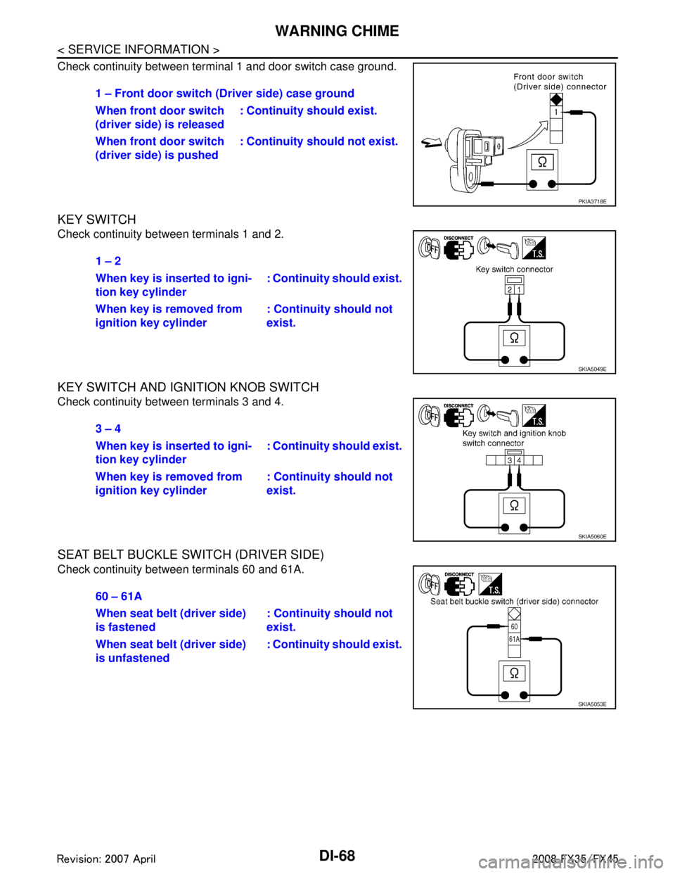
Check continuity between terminal 1 and door switch case ground.
KEY SWITCH
Check continuity between terminals 1 and 2.
KEY SWITCH AND IGNITION KNOB SWITCH
Check continuity between terminals 3 and 4.
SEAT BELT BUCKLE SWITCH (DRIVER SIDE)
Check continuity between terminals 60 and 61A.1 – Front door switch
(Driver side) case ground
When front door switch
(driver side) is released : Continuity should exist.
When front door switch
(driver side) is pushed : Continuity should not exist.
PKIA3718E
1 – 2
When key is inserted to igni-
tion key cylinder : Continuity
should exist.
When key is removed from
ignition key cylinder : Continuity should not
exist.
SKIA5049E
3 – 4
When key is inserted to igni-
tion key cylinder: Continuity
should exist.
When key is removed from
ignition key cylinder : Continuity should not
exist.
SKIA5060E
60 – 61A
When seat belt (driver side)
is fastened: Continuity should not
exist.
When seat belt (driver side)
is unfastened : Continuity
should exist.
SKIA5053E
3AA93ABC3ACD3AC03ACA3AC03AC63AC53A913A773A893A873A873A8E3A773A983AC73AC93AC03AC3
3A893A873A873A8F3A773A9D3AAF3A8A3A8C3A863A9D3AAF3A8B3A8C
Page 1197 of 3924
LANE DEPARTURE WARNING SYSTEMDI-71
< SERVICE INFORMATION >
C
DE
F
G H
I
J
L
M A
B
DI
N
O P
NOTE:
*: This indicates in a few seconds for the system check during ignition switch ON.
POWER SUPPLY AND GROUND CIRCUIT
With the ignition switch in the ON or START position, power is supplied
through 10A fuse [No. 12, located in the fuse block (J/B)]
to LDW camera unit terminal 1.
Ground is supplied
to LDW camera unit terminals 6 and 12
through grounds M45, M85 and M35.
Action TestINFOID:0000000001328494
LDW SYSTEM RUNNING TEST
WARNING:
Be careful when performing road test.
Understand “Precautions” and “System Description” well before the road test. Refer to DI-69, "
Pre-
caution for Lane Departure Warning (LDW) system" and DI-69, "System Description".
Function Check
Check the LDW system operation according to the c ondition that the warning function works. Refer to DI-69,
"System Description".
Camera Aiming AdjustmentINFOID:0000000001328495
OUTLINE
Adjust the camera aiming every time the LDW camera unit is removed or installed.
CAUTION:
Place the vehicle on the level ground when the camera aiming adjustment is operated.
Follow the CONSULT-III when ad justing the camera aiming. (Camera aiming adjustment cannot be
operated without CONSULT-III.)
PREPARATION
Keep all tires inflated to correct pressures. Adjust the tire pressure to the specified pressure value.
There is no-load in vehicle. Check if coolant, engine oil are filled up to correct level and fuel tank is full.
Shift the gear into “P” position and release the parking brake.
Clean the windshield.
NOTE:
Do not place anything reflective on t he upper surface of instrument panel.
TARGET SETTING
Preparation Aiming Adjustment Jig
Component Description
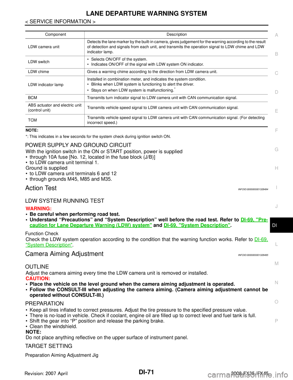
LDW camera unit Detects the lane marker by the built-in camera, gives judgement for the warning according to the result
of detection and signals from each unit, and transmits the operation signal to LDW chime and LDW
indicator lamp.
LDW switch Selects ON/OFF of the system.
Indicates ON/OFF of the signal with LDW system ON indicator.
LDW chime Gives a warning chime according to the direction from LDW camera unit.
LDW indicator lamp Installed in combination meter, and indicates the system condition.
Blinks when LDW system is functioning to alert the driver.
Stays on when LDW system is malfunctioning.
*
BCM Transmits turn indicator signal to LDW camera unit with CAN communication signal.
ABS actuator and electric unit
(control unit)
Transmits vehicle speed signal to LDW camera unit with CAN communication signal.
TCM Transmits vehicle speed signal to LDW camera unit with CAN communication signal. (For detecting
incorrect speed.)
3AA93ABC3ACD3AC03ACA3AC03AC63AC53A913A773A893A873A873A8E3A773A983AC73AC93AC03AC3
3A893A873A873A8F3A773A9D3AAF3A8A3A8C3A863A9D3AAF3A8B3A8C
Page 1207 of 3924
LANE DEPARTURE WARNING SYSTEMDI-81
< SERVICE INFORMATION >
C
DE
F
G H
I
J
L
M A
B
DI
N
O P
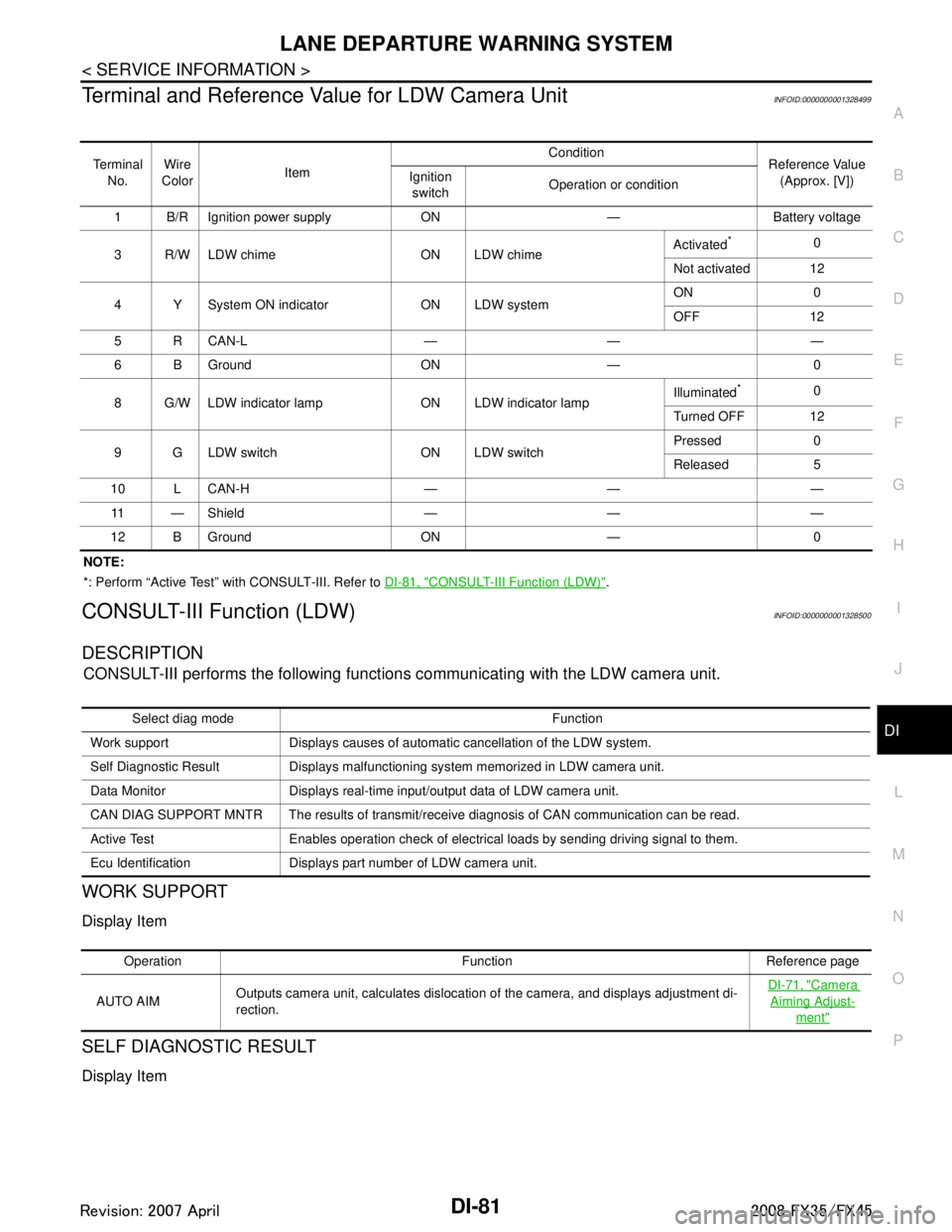
Terminal and Reference Va lue for LDW Camera UnitINFOID:0000000001328499
NOTE:
*: Perform “Active Test” with CONSULT-III. Refer to DI-81, "
CONSULT-III Function (LDW)".
CONSULT-III Function (LDW)INFOID:0000000001328500
DESCRIPTION
CONSULT-III performs the following functions communicating with the LDW camera unit.
WORK SUPPORT
Display Item
SELF DIAGNOSTIC RESULT
Display Item
Te r m i n a l
No. Wire
Color Item Condition
Reference Value
(Approx. [V])
Ignition
switch Operation or condition
1 B/R Ignition power supply ON — Battery voltage
3 R/W LDW chime ON LDW chime Activated
*0
Not activated 12
4 Y System ON indicator ON LDW system ON 0
OFF 12
5 R CAN-L — — —
6 B Ground ON — 0
8 G/W LDW indicator lamp ON LDW indicator lamp Illuminated
*0
Turned OFF 12
9 G LDW switch ON LDW switch Pressed 0
Released 5
10 L CAN-H — — — 11 — Shield — — —
12 B Ground ON — 0
Select diag mode Function
Work support Displays causes of automatic cancellation of the LDW system.
Self Diagnostic Result Displays malfunctioning system memorized in LDW camera unit.
Data Monitor Displays real-time input/output data of LDW camera unit.
CAN DIAG SUPPORT MNTR The results of transmit/receive diagnosis of CAN communication can be read.
Active Test Enables operation check of electrical loads by sending driving signal to them.
Ecu Identification Displays part number of LDW camera unit.
Operation Function Reference page
AUTO AIM Outputs camera unit, calculates dislocation of the camera, and displays adjustment di-
rection.
DI-71, "
Camera
Aiming Adjust-
ment"
3AA93ABC3ACD3AC03ACA3AC03AC63AC53A913A773A893A873A873A8E3A773A983AC73AC93AC03AC3
3A893A873A873A8F3A773A9D3AAF3A8A3A8C3A863A9D3AAF3A8B3A8C