2008 INFINITI FX35 transmission
[x] Cancel search: transmissionPage 3798 of 3924
TF-12
< SERVICE INFORMATION >
AWD SYSTEM
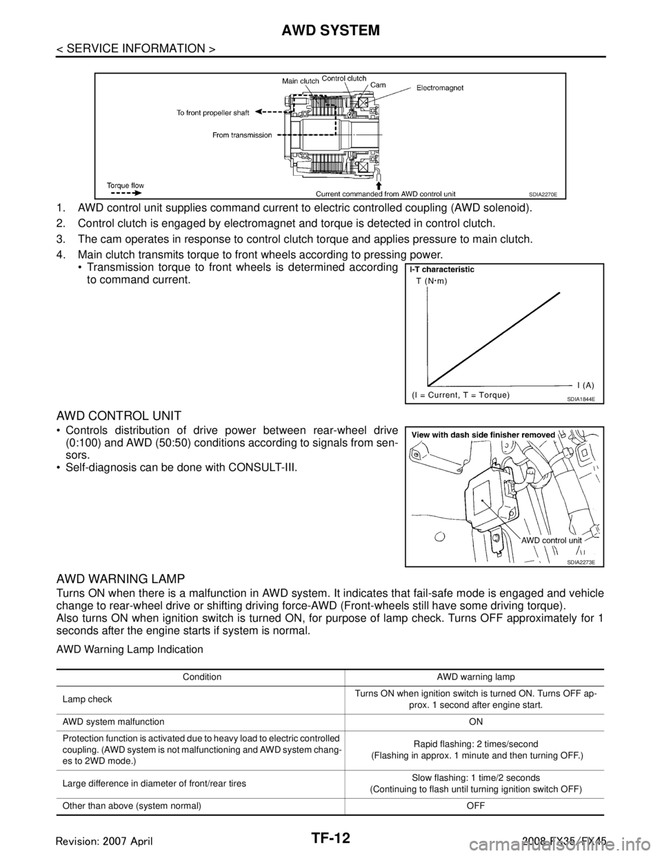
1. AWD control unit supplies command current to electric controlled coupling (AWD solenoid).
2. Control clutch is engaged by electromagnet and torque is detected in control clutch.
3. The cam operates in response to control clutch torque and applies pressure to main clutch.
4. Main clutch transmits torque to front wheels according to pressing power. Transmission torque to front wheels is determined accordingto command current.
AWD CONTROL UNIT
Controls distribution of drive power between rear-wheel drive(0:100) and AWD (50:50) conditions according to signals from sen-
sors.
Self-diagnosis can be done with CONSULT-III.
AWD WARNING LAMP
Turns ON when there is a malfunction in AWD system. It indicates that fail-safe mode is engaged and vehicle
change to rear-wheel drive or shifting driving force- AWD (Front-wheels still have some driving torque).
Also turns ON when ignition switch is turned ON, for purpose of lamp check. Turns OFF approximately for 1
seconds after the engine starts if system is normal.
AWD Warning Lamp Indication
SDIA2270E
SDIA1844E
SDIA2273E
Condition AWD warning lamp
Lamp check Turns ON when ignition switch is turned ON. Turns OFF ap-
prox. 1 second after engine start.
AWD system malfunction ON
Protection function is activated due to heavy load to electric controlled
coupling. (AWD system is not malfunctioning and AWD system chang-
es to 2WD mode.) Rapid flashing: 2 times/second
(Flashing in approx. 1 minute and then turning OFF.)
Large difference in diameter of front/rear tires Slow flashing: 1 time/2 seconds
(Continuing to flash until turning ignition switch OFF)
Other than above (system normal) OFF
3AA93ABC3ACD3AC03ACA3AC03AC63AC53A913A773A893A873A873A8E3A773A983AC73AC93AC03AC3
3A893A873A873A8F3A773A9D3AAF3A8A3A8C3A863A9D3AAF3A8B3A8C
Page 3799 of 3924
AWD SYSTEMTF-13
< SERVICE INFORMATION >
CEF
G H
I
J
K L
M A
B
TF
N
O P
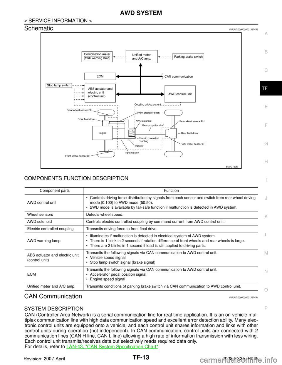
SchematicINFOID:0000000001327433
COMPONENTS FUNCTION DESCRIPTION
CAN CommunicationINFOID:0000000001327434
SYSTEM DESCRIPTION
CAN (Controller Area Network) is a serial communication li ne for real time application. It is an on-vehicle mul-
tiplex communication line with high data communication speed and excellent error detection ability. Many elec-
tronic control units are equipped onto a vehicle, and each control unit shares information and links with other
control units during operation (not independent). In CAN communication, control units are connected with 2
communication lines (CAN H line, CAN L line) allowing a high rate of information transmission with less wiring.
Each control unit transmits/receives data but selectively reads required data only.
For details, refer to LAN-43, "
CAN System Specification Chart".
SDIA2160E
Component parts Function
AWD control unit Controls driving force distribution by signals from each sensor and switch from rear wheel driving
mode (0:100) to AWD mode (50:50).
2WD mode is available by fail-safe function if malfunction is detected in AWD system.
Wheel sensors Detects wheel speed.
AWD solenoid Controls electric controlled coupling by command current from AWD control unit.
Electric controlled coupling Transmits driving force to front final drive.
AWD warning lamp Illuminates if malfunction is detected in electrical system of AWD system.
There is 1 blink in 2 seconds if rotation difference of front wheels and rear wheels is large.
There are 2 blinks in 1 second if load is still applied to driving parts.
ABS actuator and electric unit
(control unit) Transmits the following signals via CAN communication to AWD control unit.
Vehicle speed signal
Stop lamp switch signal (brake signal)
ECM Transmits the following signals via CAN communication to AWD control unit.
Accelerator pedal position signal
Engine speed signal
Unified meter and A/C amp. Transmits conditions of parking brake switch via CAN communication to AWD control unit.
3AA93ABC3ACD3AC03ACA3AC03AC63AC53A913A773A893A873A873A8E3A773A983AC73AC93AC03AC3
3A893A873A873A8F3A773A9D3AAF3A8A3A8C3A863A9D3AAF3A8B3A8C
Page 3826 of 3924
TF-40
< SERVICE INFORMATION >
TRANSFER ASSEMBLY
TRANSFER ASSEMBLY
Removal and InstallationINFOID:0000000001327460
REMOVAL
1. Remove tunnel stay with power tool. Refer to RSU-6, "Removal and Installation".
2. Remove exhaust front tube with power tool. Refer to EX-3
.
3. Remove front and rear propeller shaft. Refer to PR-4
and PR-7.
4. Disconnect transfer assembly harness connector and separate harness from transfer assembly.
5. Remove air breather hose. Refer to TF-39
.
6. Support transfer assembly and transmission assembly with a jack.
7. Remove engine rear member with power tool. Refer to EM-112
(VQ35DE) or EM-237 (VK45DE).
8. Remove transfer mounting bolts and se parate transfer from transmission.
CAUTION:
Secure transfer assembly to a jack.
INSTALLATION
Note the following, and install in the reverse order of removal.
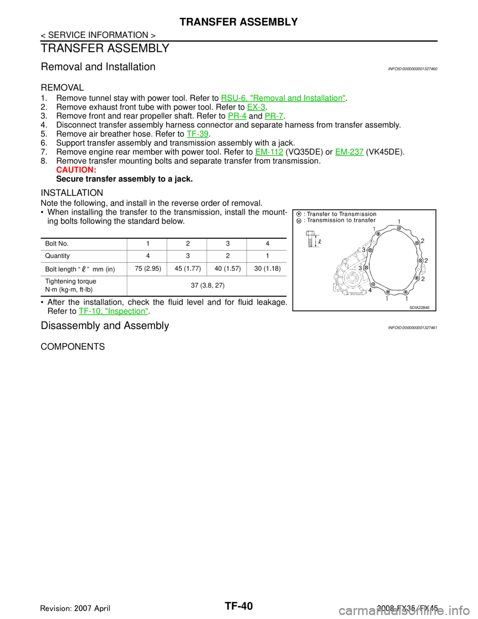
When installing the transfer to the transmission, install the mount-
ing bolts following the standard below.
After the installation, check the fluid level and for fluid leakage. Refer to TF-10, "
Inspection".
Disassembly and AssemblyINFOID:0000000001327461
COMPONENTS
Bolt No. 1234
Quantity 4321
Bolt length “ ” mm (in) 75 (2.95) 45 (1.77) 40 (1.57) 30 (1.18)
Tightening torque
N·m (kg-m, ft-lb) 37 (3.8, 27)
SDIA2284E
3AA93ABC3ACD3AC03ACA3AC03AC63AC53A913A773A893A873A873A8E3A773A983AC73AC93AC03AC3
3A893A873A873A8F3A773A9D3AAF3A8A3A8C3A863A9D3AAF3A8B3A8C
Page 3838 of 3924
TF-52
< SERVICE INFORMATION >
TRANSFER ASSEMBLY
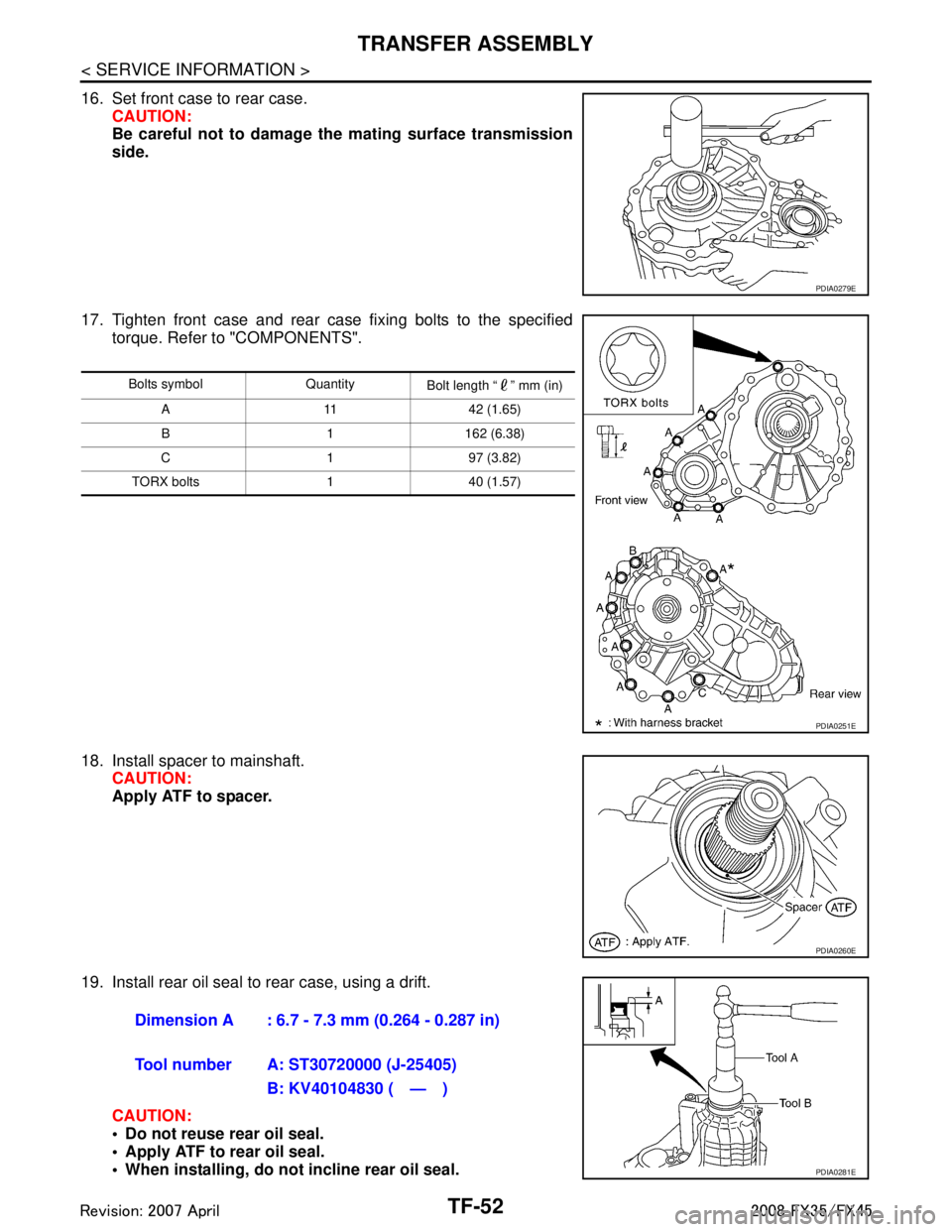
16. Set front case to rear case.CAUTION:
Be careful not to damage th e mating surface transmission
side.
17. Tighten front case and rear case fixing bolts to the specified torque. Refer to "COMPONENTS".
18. Install spacer to mainshaft. CAUTION:
Apply ATF to spacer.
19. Install rear oil seal to rear case, using a drift. CAUTION:
Do not reuse rear oil seal.
Apply ATF to rear oil seal.
When installing, do not incline rear oil seal.
PDIA0279E
Bolts symbol Quantity Bolt length “ ” mm (in)
A 11 42 (1.65)
B 1 162 (6.38)
C197 (3.82)
TORX bolts 1 40 (1.57)
PDIA0251E
PDIA0260E
Dimension A : 6.7 - 7.3 mm (0.264 - 0.287 in)
Tool number A: ST30720000 (J-25405) B: KV40104830 ( — )
PDIA0281E
3AA93ABC3ACD3AC03ACA3AC03AC63AC53A913A773A893A873A873A8E3A773A983AC73AC93AC03AC3
3A893A873A873A8F3A773A9D3AAF3A8A3A8C3A863A9D3AAF3A8B3A8C
Page 3853 of 3924
CAN COMMUNICATIONWT-13
< SERVICE INFORMATION >
C
DF
G H
I
J
K L
M A
B
WT
N
O P
CAN COMMUNICATION
System DescriptionINFOID:0000000001327578
CAN (Controller Area Network) is a serial communication li ne for real time application. It is an on-vehicle mul-
tiplex communication line with high data communication speed and excellent error detection ability. Many elec-
tronic control units are equipped onto a vehicle, and each control unit shares information and links with other
control units during operation (not independent). In CAN communication, control units are connected with 2
communication lines (CAN-H line, CAN-L line) allowing a high rate of information transmission with less wiring.
Each control unit transmits/receives data but selectively reads required data only.
Refer to LAN-43, "
CAN System Specification Chart".
3AA93ABC3ACD3AC03ACA3AC03AC63AC53A913A773A893A873A873A8E3A773A983AC73AC93AC03AC3
3A893A873A873A8F3A773A9D3AAF3A8A3A8C3A863A9D3AAF3A8B3A8C
Page 3881 of 3924

WW-6
< SERVICE INFORMATION >
FRONT WIPER AND WASHER SYSTEM
Using combination switch reading function, BCM detects ON/OFF status of INT VOLUME 1, 2, and 3.
When combination switch status is as listed below, BCM det ermines that it is wiper intermittent dial position 1.
INT VOLUME 1: ON (Continuity exists bet ween combination switch output 3 and input 1.)
INT VOLUME 2: ON (Continuity exists bet ween combination switch output 5 and input 1.)
INT VOLUME 3: ON (Continuity exists bet ween combination switch output 4 and input 2.)
BCM determines front wiper intermittent operation delay in terval from wiper intermittent dial position 1 and
vehicle speed, and sends wiper request signal (INT) to IPDM E/R.
AUTO STOP OPERATION
With wiper switch turned OFF, wiper motor will conti nue to operate until wiper arms reach windshield base.
When wiper arms are not located at base of winds hield with wiper switch OFF, ground is provided
from IPDM E/R terminal 21
to front wiper motor terminal 1, in order to continue wiper motor operation at low speed.
When wiper arms reach base of windshield, fr ont wiper motor terminals 5 and 2 are connected,
and Ground is supplied
to IPDM E/R terminal 32
through front wiper motor terminals 5 and 2
through grounds E21, E50 and E51.
Then the IPDM E/R sends auto stop operati on signal to BCM through CAN communication.
When the BCM receives auto-stop operation signal, BCM sends wiper stop signal to IPDM E/R through CAN
communication.
IPDM E/R stops wiper motor. Wiper motor will then stop wiper arms at the STOP position.
WASHER OPERATION
When wiper switch is in front wiper washer position wit h ignition switch on, BCM detects front wiper switch is
on the washer position by BCM wiper switch reading function (Refer to "COMBINATION SWITCH READING
FUNCTION"), combination switch (wiper switch) ground is supplied
to combination switch terminal 13
through front and rear washer pump terminal 1
to front and rear washer pump terminal 2
through combination switch terminal 11
to combination switch terminal 12
through grounds M35, M45 and M85.
With ground supplied, front and rear washer pump is operated.
When BCM detects that front and rear washer pump has operated for 0.4 seconds or linger, BCM operates
front wiper motor for low speed.
When BCM detects washer switch is OFF, low s peed operation cycles approximately 2 times and stops.
MIST OPERATION
When wiper switch is turned to MIST position, wiper low speed operation cycles once and then stops.
For additional information about wiper operation under this condition, Refer to "LOW SPEED WIPER OPERA-
TION".
If switch is held in MIST position, low speed operation continues.
FAIL-SAFE FUNCTION
If an abnormality occurs in CAN communications, IPDM E/ R holds the condition just before fail-safe status is
initiated until ignition switch is turned OFF. (If wipers we re operating in LO just before the initiation of fail-safe
status, they continue to operate in LO until ignition switch is turned OFF.)
COMBINATION SWITCH READING FUNCTION
Refer to BCS-4, "System Description".
CAN Communication System DescriptionINFOID:0000000001328544
CAN (Controller Area Network) is a serial communication line for real time application. It is an on-board multi-
plex communication line with high data communication speed and excellent error detection ability. Many elec-
tronic control units are equipped onto a vehicle, and each control unit shares information and links with other
control units during operation (not independent). In CA N communication, control units are connected with 2
communication lines (CAN H line, CAN L line) allowing a high rate of information transmission with less wiring.
Each control unit transmits/receives data but selectively reads required data only.
3AA93ABC3ACD3AC03ACA3AC03AC63AC53A913A773A893A873A873A8E3A773A983AC73AC93AC03AC3
3A893A873A873A8F3A773A9D3AAF3A8A3A8C3A863A9D3AAF3A8B3A8C