2008 INFINITI FX35 steering
[x] Cancel search: steeringPage 2858 of 3924
FSU-14
< SERVICE INFORMATION >
TRANSVERSE LINK
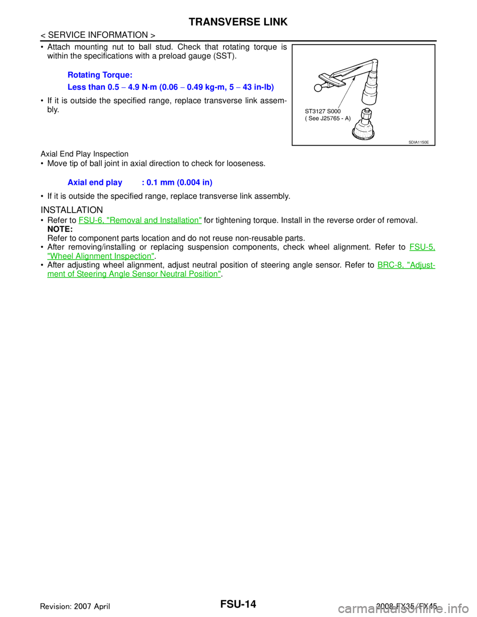
Attach mounting nut to ball stud. Check that rotating torque iswithin the specifications with a preload gauge (SST).
If it is outside the specified range, replace transverse link assem- bly.
Axial End Play Inspection
Move tip of ball joint in axial direction to check for looseness.
If it is outside the specified range, replace transverse link assembly.
INSTALLATION
Refer to FSU-6, "Removal and Installation" for tightening torque. Install in the reverse order of removal.
NOTE:
Refer to component parts location and do not reuse non-reusable parts.
After removing/installing or replacing suspension components, check wheel alignment. Refer to FSU-5,
"Wheel Alignment Inspection".
After adjusting wheel alignment, adjust neutral position of steering angle sensor. Refer to BRC-8, "
Adjust-
ment of Steering Angle Sensor Neutral Position".
Rotating Torque:
Less than 0.5
− 4.9 N·m (0.06 − 0.49 kg-m, 5 − 43 in-lb)
SDIA1150E
Axial end play : 0.1 mm (0.004 in)
3AA93ABC3ACD3AC03ACA3AC03AC63AC53A913A773A893A873A873A8E3A773A983AC73AC93AC03AC3
3A893A873A873A8F3A773A9D3AAF3A8A3A8C3A863A9D3AAF3A8B3A8C
Page 2859 of 3924
STABILIZER BARFSU-15
< SERVICE INFORMATION >
C
DF
G H
I
J
K L
M A
B
FSU
N
O P
STABILIZER BAR
Removal and InstallationINFOID:0000000001327543
REMOVAL
1. Remove tires from vehicle with power tool.
2. Remove undercover with power tool.
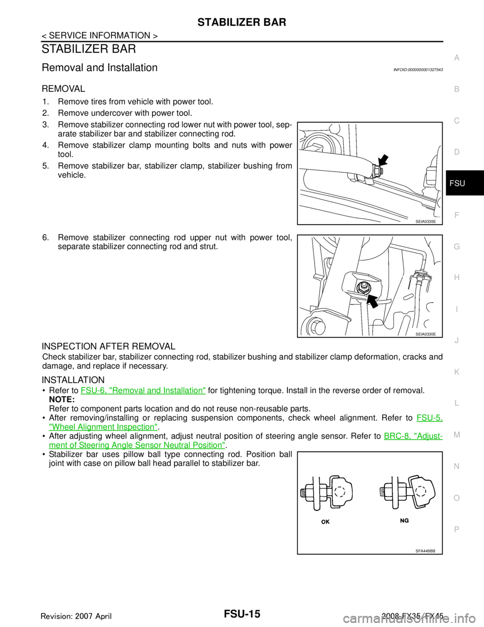
3. Remove stabilizer connecting rod lower nut with power tool, sep- arate stabilizer bar and stabilizer connecting rod.
4. Remove stabilizer clamp mounting bolts and nuts with power tool.
5. Remove stabilizer bar, stabilizer clamp, stabilizer bushing from vehicle.
6. Remove stabilizer connecting rod upper nut with power tool, separate stabilizer connecting rod and strut.
INSPECTION AFTER REMOVAL
Check stabilizer bar, stabilizer connecting rod, stabiliz er bushing and stabilizer clamp deformation, cracks and
damage, and replace if necessary.
INSTALLATION
Refer to FSU-6, "Removal and Installation" for tightening torque. Install in the reverse order of removal.
NOTE:
Refer to component parts location and do not reuse non-reusable parts.
After removing/installing or replacing suspension components, check wheel alignment. Refer to FSU-5,
"Wheel Alignment Inspection".
After adjusting wheel alignment, adjust neutral position of steering angle sensor. Refer to BRC-8, "
Adjust-
ment of Steering Angle Sensor Neutral Position".
Stabilizer bar uses pillow ball type connecting rod. Position ball
joint with case on pillow ball head parallel to stabilizer bar.
SEIA0335E
SEIA0330E
SFA449BB
3AA93ABC3ACD3AC03ACA3AC03AC63AC53A913A773A893A873A873A8E3A773A983AC73AC93AC03AC3
3A893A873A873A8F3A773A9D3AAF3A8A3A8C3A863A9D3AAF3A8B3A8C
Page 2860 of 3924
FSU-16
< SERVICE INFORMATION >
FRONT SUSPENSION MEMBER
FRONT SUSPENSION MEMBER
Removal and InstallationINFOID:0000000001327544
REMOVAL
1. Set engine slinger to engine, then suspend an engine.
2. Remove tires from vehicle with power tool.
3. Remove undercover with power tool.
4. Remove front cross bar.
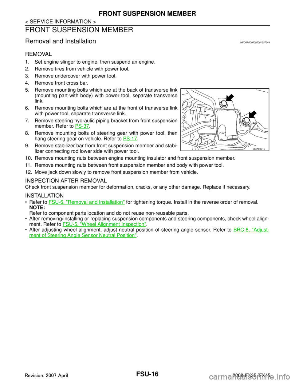
5. Remove mounting bolts which are at the back of transverse link(mounting part with body) with power tool, separate transverse
link.
6. Remove mounting bolts which are at the front of transverse link with power tool, separate transverse link.
7. Remove steering hydraulic piping bracket from front suspension member. Refer to PS-37
.
8. Remove mounting bolts of steering gear with power tool, then hang steering gear on vehicle. Refer to PS-17
.
9. Remove stabilizer bar from front suspension member and stabi- lizer connecting rod lower side with power tool.
10. Remove mounting nuts between engine mounting insulator and front suspension member.
11. Remove mounting nuts between front suspension member and body with power tool.
12. Move jack down slowly to remove front suspension member from vehicle.
INSPECTION AFTER REMOVAL
Check front suspension member for deformation, cr acks, or any other damage. Replace if necessary.
INSTALLATION
Refer to FSU-6, "Removal and Installation" for tightening torque. Install in the reverse order of removal.
NOTE:
Refer to component parts location and do not reuse non-reusable parts.
After removing/installing or replacing suspension components and steering components, check wheel align- ment. Refer to FSU-5, "
Wheel Alignment Inspection".
After adjusting wheel alignment, adjust neutral position of steering angle sensor. Refer to BRC-8, "
Adjust-
ment of Steering Angle Sensor Neutral Position".
SEIA0331E
3AA93ABC3ACD3AC03ACA3AC03AC63AC53A913A773A893A873A873A8E3A773A983AC73AC93AC03AC3
3A893A873A873A8F3A773A9D3AAF3A8A3A8C3A863A9D3AAF3A8B3A8C
Page 2863 of 3924

GI-1
GENERAL INFORMATION
C
DE
F
G H
I
J
K L
M B
GI
SECTION GI
N
O P
CONTENTS
GENERAL INFORMATION
SERVICE INFORMATION .. ..........................2
PRECAUTIONS .............................................. .....2
Description .......................................................... ......2
Precaution for Supplemental Restraint System
(SRS) "AIR BAG" and "SEAT BELT PRE-TEN-
SIONER" ...................................................................
2
Precaution Necessary for Steering Wheel Rota-
tion After Battery Disconnect .....................................
2
Precaution for Procedure without Cowl Top Cover ......3
General Precaution ...................................................3
Precaution for Three Way Catalyst ...........................4
Precaution for Fuel (Unleaded Premium Gasoline
Recommended) .........................................................
5
Precaution for Fuel (Unleaded Premium Gasoline
Required) ..................................................................
5
Precaution for Multiport Fuel Injection System or
Engine Control System .............................................
5
Precaution for Hoses .................................................5
Precaution for Engine Oils ........................................6
Precaution for the Environment .................................7
Precaution for Air Conditioning .................................7
HOW TO USE THIS MANUAL ............................8
Description .......................................................... ......8
Terms ........................................................................8
Units ..........................................................................8
Contents ....................................................................8
Component ................................................................8
How to Follow Trouble Diagnosis ..............................9
How to Read Wiring Diagram ..................................13
Abbreviations ..........................................................20
SERVICE INFORMATION FOR ELECTRICAL
INCIDENT ...........................................................
22
How to Check Terminal ....................................... ....22
How to Perform Efficient Diagnosis for an Electri-
cal Incident .......................................................... ....
25
Control Units and Electrical Parts ............................32
CONSULT-III/GST CHECKING SYSTEM .........34
Description ...............................................................34
CONSULT-III Function and System Application*1 ....34
CONSULT-III/GST Data Link Connector (DLC)
Circuit ......................................................................
35
Wiring Diagram - CONSULT-III/GST CHECKING
SYSTEM - ................................................................
36
LIFTING POINT .................................................37
Commercial Service Tool ........................................37
Garage Jack and Safety Stand ................................37
2-Pole Lift ................................................................38
Board-On Lift ...........................................................38
TOW TRUCK TOWING .....................................40
Tow Truck Towing ...................................................40
Vehicle Recovery (Freeing a Stuck Vehicle) ...........41
TIGHTENING TORQUE OF STANDARD
BOLTS ...............................................................
43
Tightening Torque Table .........................................43
RECOMMENDED CHEMICAL PRODUCTS
AND SEALANTS ...............................................
44
Recommended Chemical Product and Sealant .......44
IDENTIFICATION INFORMATION ....................45
Model Variation ........................................................45
Dimensions ..............................................................47
Wheels & Tires ........................................................47
TERMINOLOGY ................................................48
SAE J1930 Terminology List ...................................48
3AA93ABC3ACD3AC03ACA3AC03AC63AC53A913A773A893A873A873A8E3A773A983AC73AC93AC03AC3
3A893A873A873A8F3A773A9D3AAF3A8A3A8C3A863A9D3AAF3A8B3A8C
Page 2864 of 3924
GI-2
< SERVICE INFORMATION >
PRECAUTIONS
SERVICE INFORMATION
PRECAUTIONS
DescriptionINFOID:0000000001325649
Observe the following precautions to ensure safe and proper servicing. These precautions are not
described in each individual section.
Precaution for Supplemental Restraint S ystem (SRS) "AIR BAG" and "SEAT BELT
PRE-TENSIONER"
INFOID:0000000001612904
The Supplemental Restraint System such as “A IR BAG” and “SEAT BELT PRE-TENSIONER”, used along
with a front seat belt, helps to reduce the risk or severi ty of injury to the driver and front passenger for certain
types of collision. This system includes seat belt switch inputs and dual stage front air bag modules. The SRS
system uses the seat belt switches to determine the front air bag deployment, and may only deploy one front
air bag, depending on the severity of a collision and w hether the front occupants are belted or unbelted.
Information necessary to service the system safely is included in the “SUPPLEMENTAL RESTRAINT SYS-
TEM” and “SEAT BELTS” of this Service Manual.
WARNING:
• To avoid rendering the SRS inopera tive, which could increase the risk of personal injury or death in
the event of a collision which would result in air bag inflation, all maintenance must be performed by
an authorized NISS AN/INFINITI dealer.
Improper maintenance, including in correct removal and installation of the SRS, can lead to personal
injury caused by unintent ional activation of the system. For re moval of Spiral Cable and Air Bag
Module, see the “SUPPLEMEN TAL RESTRAINT SYSTEM”.
Do not use electrical test equipmen t on any circuit related to the SRS unless instructed to in this
Service Manual. SRS wiring harnesses can be identi fied by yellow and/or orange harnesses or har-
ness connectors.
Precaution Necessary for Steering W heel Rotation After Battery Disconnect
INFOID:0000000001612934
NOTE:
This Procedure is applied only to models with In telligent Key system and NVIS/IVIS (NISSAN/INFINITI
VEHICLE IMMOBILIZER SYSTEM - NATS).
Remove and install all control units after disconnecting both battery cables with the ignition knob in the ″LOCK ″ position.
Always use CONSULT-III to perform self-diagnosis as a part of each function inspection after finishing work.
If DTC is detected, perform trouble diagnosis according to self-diagnostic results.
For models equipped with the Intelligent Key system and NVIS /IVIS, an electrically controlled steering lock
mechanism is adopted on the key cylinder.
For this reason, if the battery is disconnected or if the battery is discharged, the steering wheel will lock and
steering wheel rotation will become impossible.
If steering wheel rotation is required when battery pow er is interrupted, follow the procedure below before
starting the repair operation.
OPERATION PROCEDURE
1. Connect both battery cables. NOTE:
Supply power using jumper cables if battery is discharged.
2. Use the Intelligent Key or mechanical key to turn the ignition switch to the ″ACC ″ position. At this time, the
steering lock will be released.
3. Disconnect both battery cables. The steering lock will remain released and the steering wheel can be
rotated.
4. Perform the necessary repair operation.
5. When the repair work is completed, return the ignition switch to the ″LOCK ″ position before connecting
the battery cables. (At this time, the steering lock mechanism will engage.)
6. Perform a self-diagnosis check of all control units using CONSULT-III.
3AA93ABC3ACD3AC03ACA3AC03AC63AC53A913A773A893A873A873A8E3A773A983AC73AC93AC03AC3
3A893A873A873A8F3A773A9D3AAF3A8A3A8C3A863A9D3AAF3A8B3A8C
Page 2883 of 3924

HOW TO USE THIS MANUALGI-21
< SERVICE INFORMATION >
C
DE
F
G H
I
J
K L
M B
GI
N
O PLH, RH Left-Hand, Right-Hand M/T Manual Transaxle/TransmissionOD Overdrive
P/S Power Steering
SAE Society of Automotive Engineers, Inc.
SDS Service Data and Specifications SST Special Service Tools
2WD 2-Wheel Drive 2
22nd range 2nd gear
2
12nd range 1st gear
1
21st range 2nd gear
1
11st range 1st gear
ABBREVIATION DESCRIPTION
3AA93ABC3ACD3AC03ACA3AC03AC63AC53A913A773A893A873A873A8E3A773A983AC73AC93AC03AC3
3A893A873A873A8F3A773A9D3AAF3A8A3A8C3A863A9D3AAF3A8B3A8C
Page 2902 of 3924
GI-40
< SERVICE INFORMATION >
TOW TRUCK TOWING
TOW TRUCK TOWING
Tow Truck TowingINFOID:0000000001325684
CAUTION:
All applicable state or Provincial (in Canada) laws and local laws regarding the towing operation
must be obeyed.
It is necessary to use proper towi ng equipment to avoid possible damage to the vehicle during tow-
ing operation. To wing is in accordance with Towing Procedure Manual at dealer.
Always attach safety chains before towing.
When towing, make sure that the transmission, steering system and powertrain are in good order. If
any unit is damaged, dollies must be used.
Never tow an automatic transmission model from the rear (that is backward) with four wheels on the
ground. This may cause serious and exp ensive damage to the transmission.
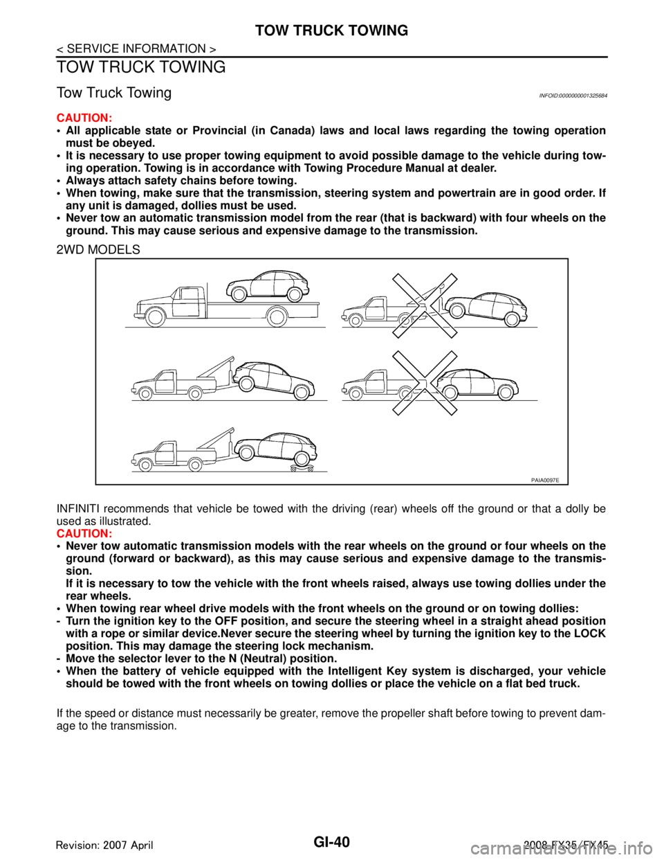
2WD MODELS
INFINITI recommends that vehicle be towed with the dr iving (rear) wheels off the ground or that a dolly be
used as illustrated.
CAUTION:
Never tow automatic transmission models with the r ear wheels on the ground or four wheels on the
ground (forward or backward), as this may cause serious and expensive damage to the transmis-
sion.
If it is necessary to tow the vehicle with the fron t wheels raised, always use towing dollies under the
rear wheels.
When towing rear wheel drive mo dels with the front wheels on the ground or on towing dollies:
- Turn the ignition key to the OFF position, and secure the steering wh eel in a straight ahead position
with a rope or similar device.Never secure the st eering wheel by turning the ignition key to the LOCK
position. This may damage the steering lock mechanism.
- Move the selector lever to the N (Neutral) position.
When the battery of vehicle equipped with the Intelligent Key system is discharged, your vehicle
should be towed with the front wh eels on towing dollies or place the vehicle on a flat bed truck.
If the speed or distance must necessarily be greater, re move the propeller shaft before towing to prevent dam-
age to the transmission.
PAIA0097E
3AA93ABC3ACD3AC03ACA3AC03AC63AC53A913A773A893A873A873A8E3A773A983AC73AC93AC03AC3
3A893A873A873A8F3A773A9D3AAF3A8A3A8C3A863A9D3AAF3A8B3A8C
Page 2904 of 3924

GI-42
< SERVICE INFORMATION >
TOW TRUCK TOWING
3. Turn the steering wheel right and left to clear an area around the front tires.
4. Slowly rock the vehicle forward and backward.Shift back and forth between R (reverse) and D (drive).
Apply the accelerator as little as possible to maintain the rocking motion.
Release the accelerator pedal before shifting between R and D.
Do not spin the tires above 35 mph (55 km/h).
5. If the vehicle can not be freed after a few tries, cont act a professional towing service to remove the vehi-
cle.
3AA93ABC3ACD3AC03ACA3AC03AC63AC53A913A773A893A873A873A8E3A773A983AC73AC93AC03AC3
3A893A873A873A8F3A773A9D3AAF3A8A3A8C3A863A9D3AAF3A8B3A8C