2008 INFINITI FX35 check oil
[x] Cancel search: check oilPage 2855 of 3924
COIL SPRING AND STRUTFSU-11
< SERVICE INFORMATION >
C
DF
G H
I
J
K L
M A
B
FSU
N
O P
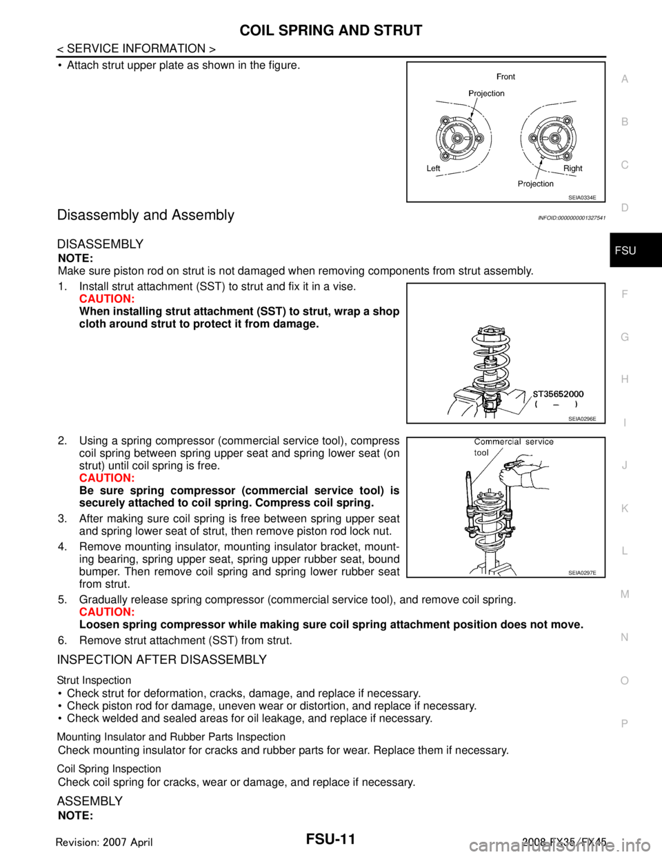
Attach strut upper plate as shown in the figure.
Disassembly and AssemblyINFOID:0000000001327541
DISASSEMBLY
NOTE:
Make sure piston rod on strut is not damaged when removing components from strut assembly.
1. Install strut attachment (SST) to strut and fix it in a vise. CAUTION:
When installing strut attachment (SST) to strut, wrap a shop
cloth around strut to protect it from damage.
2. Using a spring compressor (commercial service tool), compress coil spring between spring upper seat and spring lower seat (on
strut) until coil spring is free.
CAUTION:
Be sure spring compressor (commercial service tool) is
securely attached to coil sp ring. Compress coil spring.
3. After making sure coil spring is free between spring upper seat and spring lower seat of strut, then remove piston rod lock nut.
4. Remove mounting insulator, mounting insulator bracket, mount- ing bearing, spring upper seat, spring upper rubber seat, bound
bumper. Then remove coil spring and spring lower rubber seat
from strut.
5. Gradually release spring compressor (commercial service tool), and remove coil spring. CAUTION:
Loosen spring compressor whil e making sure coil spring attachment position does not move.
6. Remove strut attachment (SST) from strut.
INSPECTION AFTER DISASSEMBLY
Strut Inspection
Check strut for deformation, cracks, damage, and replace if necessary.
Check piston rod for damage, uneven wear or distortion, and replace if necessary.
Check welded and sealed areas for oil leakage, and replace if necessary.
Mounting Insulator and Rubber Parts Inspection
Check mounting insulator for cracks and rubber parts for wear. Replace them if necessary.
Coil Spring Inspection
Check coil spring for cracks, wear or damage, and replace if necessary.
ASSEMBLY
NOTE:
SEIA0334E
SEIA0296E
SEIA0297E
3AA93ABC3ACD3AC03ACA3AC03AC63AC53A913A773A893A873A873A8E3A773A983AC73AC93AC03AC3
3A893A873A873A8F3A773A9D3AAF3A8A3A8C3A863A9D3AAF3A8B3A8C
Page 2863 of 3924
GI-1
GENERAL INFORMATION
C
DE
F
G H
I
J
K L
M B
GI
SECTION GI
N
O P
CONTENTS
GENERAL INFORMATION
SERVICE INFORMATION .. ..........................2
PRECAUTIONS .............................................. .....2
Description .......................................................... ......2
Precaution for Supplemental Restraint System
(SRS) "AIR BAG" and "SEAT BELT PRE-TEN-
SIONER" ...................................................................
2
Precaution Necessary for Steering Wheel Rota-
tion After Battery Disconnect .....................................
2
Precaution for Procedure without Cowl Top Cover ......3
General Precaution ...................................................3
Precaution for Three Way Catalyst ...........................4
Precaution for Fuel (Unleaded Premium Gasoline
Recommended) .........................................................
5
Precaution for Fuel (Unleaded Premium Gasoline
Required) ..................................................................
5
Precaution for Multiport Fuel Injection System or
Engine Control System .............................................
5
Precaution for Hoses .................................................5
Precaution for Engine Oils ........................................6
Precaution for the Environment .................................7
Precaution for Air Conditioning .................................7
HOW TO USE THIS MANUAL ............................8
Description .......................................................... ......8
Terms ........................................................................8
Units ..........................................................................8
Contents ....................................................................8
Component ................................................................8
How to Follow Trouble Diagnosis ..............................9
How to Read Wiring Diagram ..................................13
Abbreviations ..........................................................20
SERVICE INFORMATION FOR ELECTRICAL
INCIDENT ...........................................................
22
How to Check Terminal ....................................... ....22
How to Perform Efficient Diagnosis for an Electri-
cal Incident .......................................................... ....
25
Control Units and Electrical Parts ............................32
CONSULT-III/GST CHECKING SYSTEM .........34
Description ...............................................................34
CONSULT-III Function and System Application*1 ....34
CONSULT-III/GST Data Link Connector (DLC)
Circuit ......................................................................
35
Wiring Diagram - CONSULT-III/GST CHECKING
SYSTEM - ................................................................
36
LIFTING POINT .................................................37
Commercial Service Tool ........................................37
Garage Jack and Safety Stand ................................37
2-Pole Lift ................................................................38
Board-On Lift ...........................................................38
TOW TRUCK TOWING .....................................40
Tow Truck Towing ...................................................40
Vehicle Recovery (Freeing a Stuck Vehicle) ...........41
TIGHTENING TORQUE OF STANDARD
BOLTS ...............................................................
43
Tightening Torque Table .........................................43
RECOMMENDED CHEMICAL PRODUCTS
AND SEALANTS ...............................................
44
Recommended Chemical Product and Sealant .......44
IDENTIFICATION INFORMATION ....................45
Model Variation ........................................................45
Dimensions ..............................................................47
Wheels & Tires ........................................................47
TERMINOLOGY ................................................48
SAE J1930 Terminology List ...................................48
3AA93ABC3ACD3AC03ACA3AC03AC63AC53A913A773A893A873A873A8E3A773A983AC73AC93AC03AC3
3A893A873A873A8F3A773A9D3AAF3A8A3A8C3A863A9D3AAF3A8B3A8C
Page 2866 of 3924
GI-4
< SERVICE INFORMATION >
PRECAUTIONS
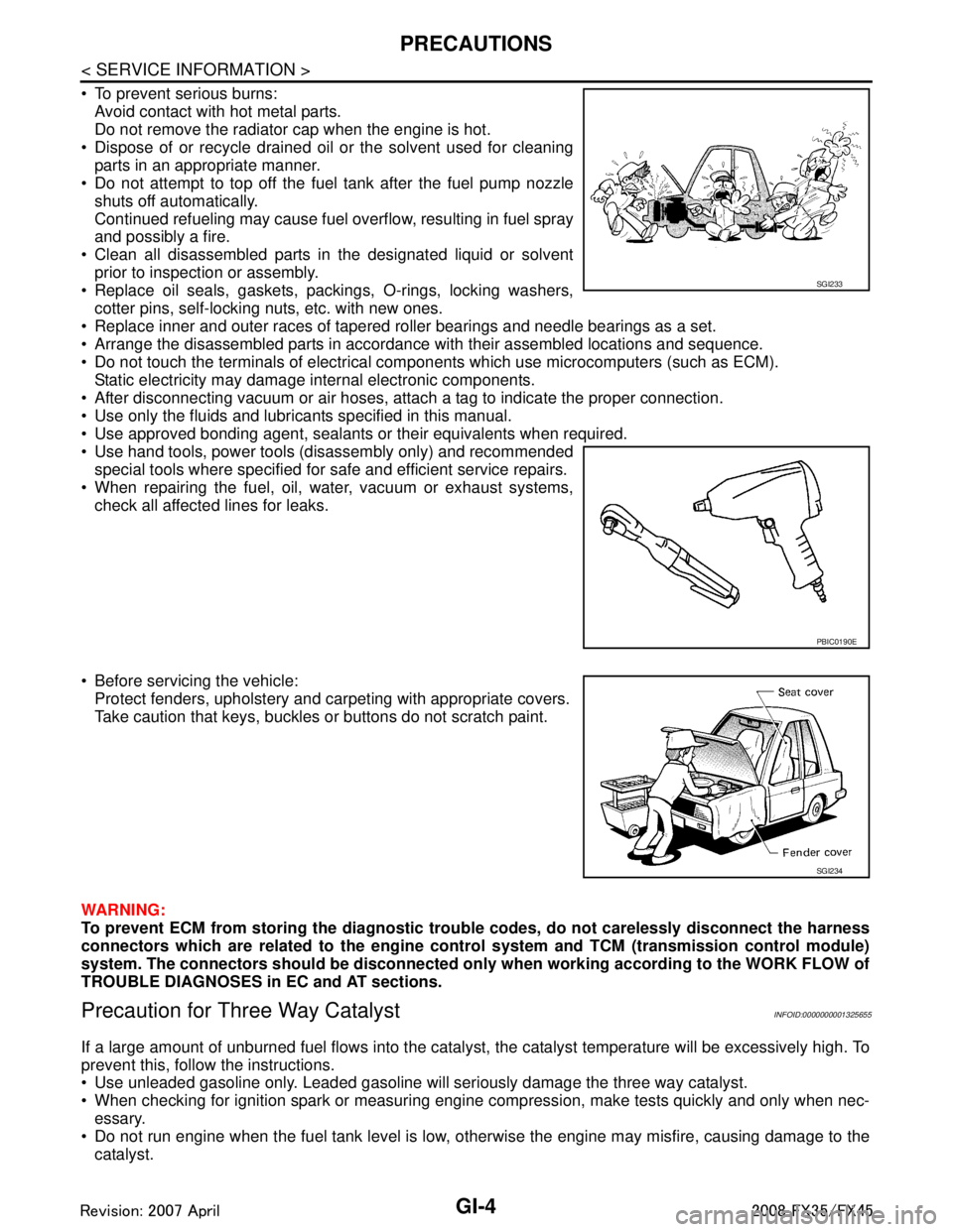
To prevent serious burns:Avoid contact with hot metal parts.
Do not remove the radiator cap when the engine is hot.
Dispose of or recycle drained oil or the solvent used for cleaning parts in an appropriate manner.
Do not attempt to top off the fuel tank after the fuel pump nozzle
shuts off automatically.
Continued refueling may cause fuel overflow, resulting in fuel spray
and possibly a fire.
Clean all disassembled parts in the designated liquid or solvent prior to inspection or assembly.
Replace oil seals, gaskets, packings, O-rings, locking washers, cotter pins, self-locking nuts, etc. with new ones.
Replace inner and outer races of tapered roller bearings and needle bearings as a set.
Arrange the disassembled parts in accordance with their assembled locations and sequence.
Do not touch the terminals of electrical com ponents which use microcomputers (such as ECM).
Static electricity may damage internal electronic components.
After disconnecting vacuum or air hoses, atta ch a tag to indicate the proper connection.
Use only the fluids and lubricants specified in this manual.
Use approved bonding agent, sealants or their equivalents when required.
Use hand tools, power tools (disassembly only) and recommended special tools where specified for safe and efficient service repairs.
When repairing the fuel, oil, water, vacuum or exhaust systems,
check all affected lines for leaks.
Before servicing the vehicle: Protect fenders, upholstery and carpeting with appropriate covers.
Take caution that keys, buckles or buttons do not scratch paint.
WARNING:
To prevent ECM from storing the diagnostic tro uble codes, do not carelessly disconnect the harness
connectors which are related to the engine cont rol system and TCM (transmission control module)
system. The connectors should be disconnected on ly when working according to the WORK FLOW of
TROUBLE DIAGNOSES in EC and AT sections.
Precaution for Three Way CatalystINFOID:0000000001325655
If a large amount of unburned fuel flows into the catalyst , the catalyst temperature will be excessively high. To
prevent this, follow the instructions.
Use unleaded gasoline only. Leaded gasoline will seriously damage the three way catalyst.
When checking for ignition spark or measuring engine compression, make tests quickly and only when nec- essary.
Do not run engine when the fuel tank level is low, otherwise the engine may misfire, causing damage to the
catalyst.
SGI233
PBIC0190E
SGI234
3AA93ABC3ACD3AC03ACA3AC03AC63AC53A913A773A893A873A873A8E3A773A983AC73AC93AC03AC3
3A893A873A873A8F3A773A9D3AAF3A8A3A8C3A863A9D3AAF3A8B3A8C
Page 2894 of 3924
GI-32
< SERVICE INFORMATION >
SERVICE INFORMATION FOR ELECTRICAL INCIDENT
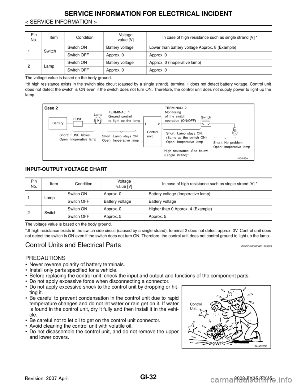
The voltage value is based on the body ground.
*:If high resistance exists in the switch side circuit (caused by a single strand), terminal 1 does not detect battery voltage. Control unit
does not detect the switch is ON even if the switch does not turn ON. Therefore, the control unit does not supply power to ligh t up the
lamp.
INPUT-OUTPUT VOLTAGE CHART
The voltage value is based on the body ground.
*:If high resistance exists in the switch side circuit (caused by a single strand), terminal 2 does not detect approx. 0V. Cont rol unit does
not detect the switch is ON even if the switch does not turn ON. Therefore, the control unit does not control ground to light u p the lamp.
Control Units and Electrical PartsINFOID:0000000001325673
PRECAUTIONS
Never reverse polarity of battery terminals.
Install only parts specified for a vehicle.
Before replacing the control unit, check the input and output and functions of the component parts.
Do not apply excessive force when disconnecting a connector.
Do not apply excessive shock to the control unit by dropping or hit- ting it.
Be careful to prevent condensation in the control unit due to rapid temperature changes and do not let water or rain get on it. If water
is found in the control unit, dry it fully and then install it in the vehi-
cle.
Be careful not to let oil to get on the control unit connector.
Avoid cleaning the control unit with volatile oil.
Do not disassemble the control unit, and do not remove the upper and lower covers.
Pin
No. Item Condition
Vo l ta g e
value [V] In case of high resistance such as single strand [V] *
1Switch Switch ON Battery voltage Lower than battery voltage Approx. 8 (Example)
Switch OFF Approx. 0 Approx. 0
2Lamp Switch ON Battery voltage App
rox. 0 (Inoperative lamp)
Switch OFF Approx. 0 Approx. 0
MGI035A
Pin
No. Item Condition
Vo l ta g e
value [V] In case of high resistance such as single strand [V] *
1Lamp Switch ON Approx. 0 Battery voltage (Inoperative lamp)
Switch OFF Battery voltage Battery voltage
2Switch Switch ON Approx. 0 Higher than 0 Approx. 4 (Example)
Switch OFF Approx. 5 Approx. 5
SAIA0255E
3AA93ABC3ACD3AC03ACA3AC03AC63AC53A913A773A893A873A873A8E3A773A983AC73AC93AC03AC3
3A893A873A873A8F3A773A9D3AAF3A8A3A8C3A863A9D3AAF3A8B3A8C
Page 2990 of 3924
REAR WINDOW DEFOGGERGW-77
< SERVICE INFORMATION >
C
DE
F
G H
J
K L
M A
B
GW
N
O P
CAN communication line check is performed. Refer to AV-79, "CAN Communication Check".
OK or NG
OK >> Check condition of harness and connector.
NG >> In addition, it is necessary to check CAN communication line. Refer to AV-79, "
CAN Communica-
tion Check".
Check FilamentINFOID:0000000001328018
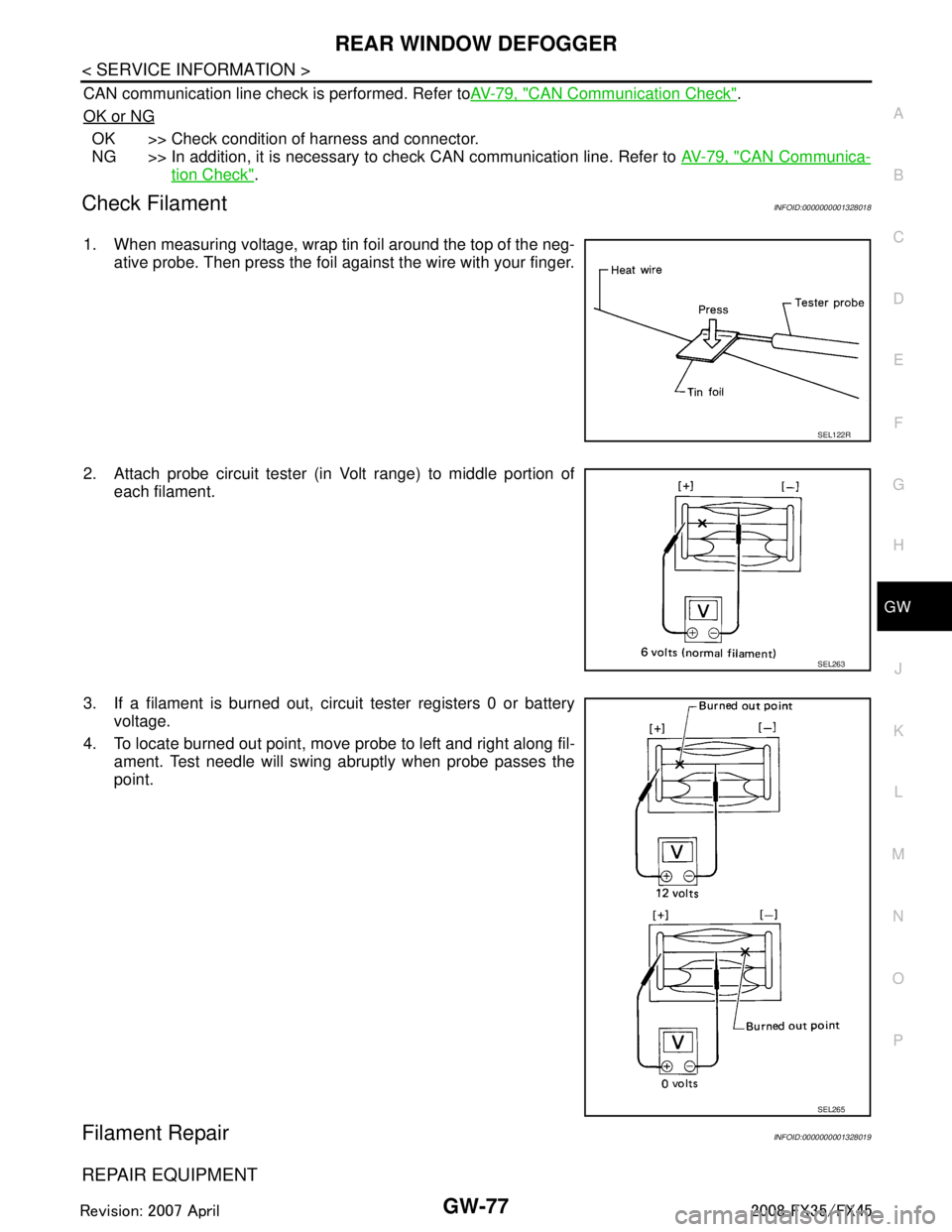
1. When measuring voltage, wrap tin foil around the top of the neg-
ative probe. Then press the foil against the wire with your finger.
2. Attach probe circuit tester (in Volt range) to middle portion of each filament.
3. If a filament is burned out, circuit tester registers 0 or battery voltage.
4. To locate burned out point, move probe to left and right along fil- ament. Test needle will swing abruptly when probe passes the
point.
Filament RepairINFOID:0000000001328019
REPAIR EQUIPMENT
SEL122R
SEL263
SEL265
3AA93ABC3ACD3AC03ACA3AC03AC63AC53A913A773A893A873A873A8E3A773A983AC73AC93AC03AC3
3A893A873A873A8F3A773A9D3AAF3A8A3A8C3A863A9D3AAF3A8B3A8C
Page 3067 of 3924
![INFINITI FX35 2008 Service Manual
TROUBLE DIAGNOSISLAN-47
< SERVICE INFORMATION > [CAN]
C
D
E
F
G H
I
J
L
M A
B
LAN
N
O P
ICC steering switch signal T R
Malfunctioning indicator lamp signal T R
Snow mode switch signal RT
TR
Wide open INFINITI FX35 2008 Service Manual
TROUBLE DIAGNOSISLAN-47
< SERVICE INFORMATION > [CAN]
C
D
E
F
G H
I
J
L
M A
B
LAN
N
O P
ICC steering switch signal T R
Malfunctioning indicator lamp signal T R
Snow mode switch signal RT
TR
Wide open](/manual-img/42/57017/w960_57017-3066.png)
TROUBLE DIAGNOSISLAN-47
< SERVICE INFORMATION > [CAN]
C
D
E
F
G H
I
J
L
M A
B
LAN
N
O P
ICC steering switch signal T R
Malfunctioning indicator lamp signal T R
Snow mode switch signal RT
TR
Wide open throttle position signal T R
A/C switch/indicator signal TR
RT
System setting signal TR R
RT T
Buzzer output signal TR
TR
TR
ICC OD cancel request signal T R
ICC operation signal R T
ICC system display signal T R
ICC warning lamp signal T R
A/T CHECK indicator lamp signal T R
A/T self-diagnosis signal R T
Current gear position signal R T R
Manual mode indicator signal R T R
Output shaft revolution signal R R T R
P range signal R T R R
Shift position indicator signal R T R
Turbine revolution signal R R T
A/C switch signal R T
Blower fan motor switch signal R T
Day time running light request signal T R
Door lock/unlock status signal T R
Door switch signal R T R R R R
Front fog light request signal T R
Front wiper request signal R T R
High beam request signal T R R
Horn chirp signal T R
Ignition switch signal T R R
Key fob door unlock signal T R
Key fob ID signal T R
Key switch signal T R
Low beam request signal T R
Oil pressure switch signal RT
TR
Position light request signal T R R
Rear window defogger switch signal T R
Run flat tire warning lamp signal T R Signal name/Connecting unit
ECM
DISP ICC
TCM
BCM
I-KEY
LANE
STRG M&AABS
LASER ADP
IPDM-E
3AA93ABC3ACD3AC03ACA3AC03AC63AC53A913A773A893A873A873A8E3A773A983AC73AC93AC03AC3
3A893A873A873A8F3A773A9D3AAF3A8A3A8C3A863A9D3AAF3A8B3A8C
Page 3072 of 3924
![INFINITI FX35 2008 Service Manual
LAN-52
< SERVICE INFORMATION >[CAN]
TROUBLE DIAGNOSIS
ICC operation signal R T
ICC system display signal T R
ICC warning lamp signal T R
A/T CHECK indicator lamp signal T R
A/T self-diagnosis signal INFINITI FX35 2008 Service Manual
LAN-52
< SERVICE INFORMATION >[CAN]
TROUBLE DIAGNOSIS
ICC operation signal R T
ICC system display signal T R
ICC warning lamp signal T R
A/T CHECK indicator lamp signal T R
A/T self-diagnosis signal](/manual-img/42/57017/w960_57017-3071.png)
LAN-52
< SERVICE INFORMATION >[CAN]
TROUBLE DIAGNOSIS
ICC operation signal R T
ICC system display signal T R
ICC warning lamp signal T R
A/T CHECK indicator lamp signal T R
A/T self-diagnosis signal R T
Current gear position signal R T R
Manual mode indicator signal R T R
Output shaft revolution signal R R T R
P range signal R T R R
Shift position indicator signal R T R
Turbine revolution signal R R T
A/C switch signal R T
Blower fan motor switch signal R T
Day time running light request signal T R
Door lock/unlock status signal T R
Door switch signal R T R R R R
Front fog light request signal T R
Front wiper request signal R T R
High beam request signal T R R
Horn chirp signal T R
Ignition switch signal T R R
Key fob door unlock signal T R
Key fob ID signal T R
Key switch signal T R
Low beam request signal T R
Oil pressure switch signalRT
TR
Position light request signal R T R R
Rear window defogger switch signal T R
Run flat tire warning lamp signal T R
Sleep wake up signal TRRR
RT
Theft warning horn request signal T R
Tire pressure warning lamp signal T R
Turn indicator signal T R R
Alarm request signal R T
Back door open request signal R T
Door lock/unlock request signal R T
Ignition knob switch signal R T
Key warning signal T R
Power window open request signal R T
Steering angle sensor signal T R
Distance to empty signal R T Signal name/Connecting unit
ECM
4WD
DISP ICC
TCM
BCM
I-KEY
LANE
STRG M&A
ABS
LASER ADP
IPDM-E
3AA93ABC3ACD3AC03ACA3AC03AC63AC53A913A773A893A873A873A8E3A773A983AC73AC93AC03AC3
3A893A873A873A8F3A773A9D3AAF3A8A3A8C3A863A9D3AAF3A8B3A8C
Page 3106 of 3924
LT-4
< SERVICE INFORMATION >
PRECAUTIONS
SERVICE INFORMATION
PRECAUTIONS
Precaution for Supplemental Restraint System (SRS) "AIR BAG" and "SEAT BELT
PRE-TENSIONER"
INFOID:0000000001612924
The Supplemental Restraint System such as “A IR BAG” and “SEAT BELT PRE-TENSIONER”, used along
with a front seat belt, helps to reduce the risk or severi ty of injury to the driver and front passenger for certain
types of collision. This system includes seat belt switch inputs and dual stage front air bag modules. The SRS
system uses the seat belt switches to determine the front air bag deployment, and may only deploy one front
air bag, depending on the severity of a collision and w hether the front occupants are belted or unbelted.
Information necessary to service the system safely is included in the “SUPPLEMENTAL RESTRAINT SYS-
TEM” and “SEAT BELTS” of this Service Manual.
WARNING:
• To avoid rendering the SRS inopera tive, which could increase the risk of personal injury or death in
the event of a collision which would result in air bag inflation, all maintenance must be performed by
an authorized NISS AN/INFINITI dealer.
Improper maintenance, including in correct removal and installation of the SRS, can lead to personal
injury caused by unintent ional activation of the system. For re moval of Spiral Cable and Air Bag
Module, see the “SUPPLEMEN TAL RESTRAINT SYSTEM”.
Do not use electrical test equipmen t on any circuit related to the SRS unless instructed to in this
Service Manual. SRS wiring harnesses can be identi fied by yellow and/or orange harnesses or har-
ness connectors.
General Precaution for Service OperationINFOID:0000000001328264
Never work with wet hands.
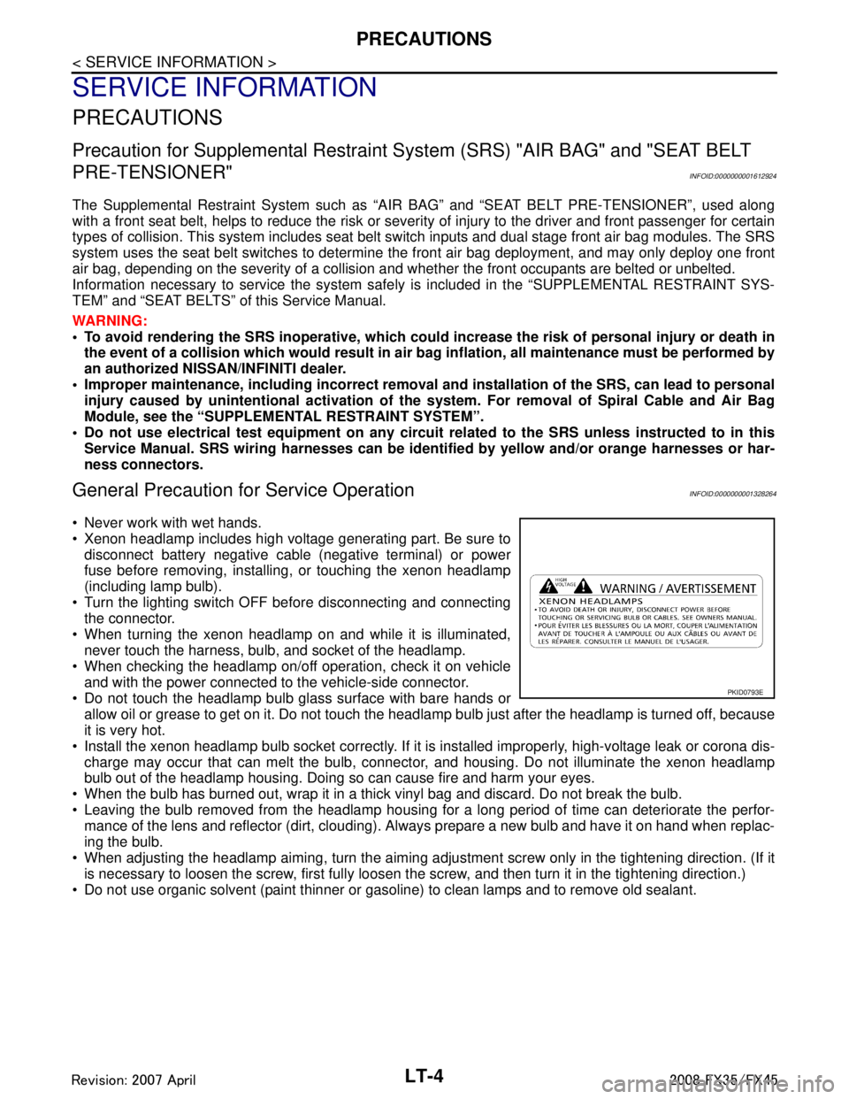
Xenon headlamp includes high voltage generating part. Be sure to disconnect battery negative cable (negative terminal) or power
fuse before removing, installing, or touching the xenon headlamp
(including lamp bulb).
Turn the lighting switch OFF before disconnecting and connecting the connector.
When turning the xenon headlamp on and while it is illuminated, never touch the harness, bulb, and socket of the headlamp.
When checking the headlamp on/off operation, check it on vehicle
and with the power connected to the vehicle-side connector.
Do not touch the headlamp bulb glass surface with bare hands or allow oil or grease to get on it. Do not touch the headl amp bulb just after the headlamp is turned off, because
it is very hot.
Install the xenon headlamp bulb socket co rrectly. If it is installed improperly, high-voltage leak or corona dis-
charge may occur that can melt the bulb, connecto r, and housing. Do not illuminate the xenon headlamp
bulb out of the headlamp housing. Doing so can cause fire and harm your eyes.
When the bulb has burned out, wrap it in a thick vinyl bag and discard. Do not break the bulb.
Leaving the bulb removed from the headlamp housing for a long period of time can deteriorate the perfor- mance of the lens and reflector (dirt, clouding). Al ways prepare a new bulb and have it on hand when replac-
ing the bulb.
When adjusting the headlamp aiming, turn the aiming adjus tment screw only in the tightening direction. (If it
is necessary to loosen the screw, first fully loosen the screw, and then turn it in the tightening direction.)
Do not use organic solvent (paint thinner or gasoline) to clean lamps and to remove old sealant.
PKID0793E
3AA93ABC3ACD3AC03ACA3AC03AC63AC53A913A773A893A873A873A8E3A773A983AC73AC93AC03AC3
3A893A873A873A8F3A773A9D3AAF3A8A3A8C3A863A9D3AAF3A8B3A8C